

2012-2014 Mazda Mazda5 Service & Repair Manual
What's Included?
Fast Download Speeds
Offline Viewing
Access Contents & Bookmarks
Full Search Facility
Print one or all pages of your manual
Title Section
GENERAL INFORMATION 00
BODY
STRUCTURE
BODY STRUCTURE 80A
PANEL REPLACEMENT 80B
WATER-PROOF AND RUST
PREVENTIVE
80C
DIMENSIONS 80D
PLASTIC BODY PARTS 80E
CONSTRUCTION
STANDARD VALVES
80F
CONTENTS
2012-present
Bodyshop
Manual
FOREWORD
This bodyshop manual is intended for
use by technicians of Authorized Mazda
Dealers to help them service and repair
Mazda vehicles. It can also be useful to
owners and operators of Mazda vehicles in
performing limited repair and maintenance
on Mazda vehicles.
For proper repair and maintenance, a
thorough familiarization with this manual is
important, and it should always be kept in a
handy place for quick and easy reference.
All the contents of this manual, including
drawings and specifications, are the latest
available at the time of printing.
As modifications affecting repair or
maintenance occur, relevant information
supplementary to this volume will be made
available at Mazda dealers. This manual
should be kept up-to-date.
Mazda Motor Corporation reserves the
right to alter the specifications and contents
of this manual without obligation or ad-
vance notice.
All rights reserved. No part of this book may
be reproduced or used in any form or
by any means, electronic or mechanical
including photocopying and recording and
the use of any kind of information storage
and retrieval system-without permission in
writing.
Mazda Motor Corporation
HIROSHIMA, JAPAN
APPLICATION:
This manual is applicable to vehicles beginning
with the Vehicle Identification Numbers (VIN),
shown on the following page.
© 2010 Mazda Motor Corporation
PRINTED IN U.S.A., OCTOBER 2010
Form No. 3494–1U–10J
Part No. 9999–95–030F–12

VEHICLE IDENTIFICATION NUMBERS (VIN)
JM1 CW2✻L✻C# 100001—

00
GENERAL INFORMATION
00-00–1
SECTION
00-00
Toc of SCT
GENERAL INFORMATION . . . . 00-00
Toc of SCT
00-00 GENERAL INFORMATION
VEHICLE IDENTIFICATION NUMBER
(VIN) CODE . . . . . . . . . . . . . . . . . . . . . . 00-00–2
2012 Model Year . . . . . . . . . . . . . . . . . . 00-00–2
VEHICLE IDENTIFICATION NUMBERS
(VIN) . . . . . . . . . . . . . . . . . . . . . . . . . . . . 00-00–2
2012 Model Year . . . . . . . . . . . . . . . . . . 00-00–2
HOW TO USE THIS MANUAL . . . . . . . . . 00-00–3
Efficient Replacement of
Body Panels . . . . . . . . . . . . . . . . . . . . 00-00–3
Symbols of Panel Replacement . . . . . . 00-00–3
Body Dimensions
(Flat-plane Dimensions) . . . . . . . . . . . 00-00–4
Body Dimensions
(Straight-line Dimensions) . . . . . . . . . . 00-00–6
Symbols of Body Dimensions . . . . . . . . 00-00–7
AIR BAG SYSTEM
SERVICE WARNINGS . . . . . . . . . . . . . . 00-00–8
Air Bag Module Inspection . . . . . . . . . . 00-00–8
Air Bag Module Handling . . . . . . . . . . . 00-00–8
Side Air Bag Module Handling . . . . . . . 00-00–8
SAS Control Module Handling . . . . . . . 00-00–9
Side Air Bag Sensor Handling. . . . . . . . 00-00–9
Pre-tensioner Seat Belt Inspection . . . . 00-00–9
Lap Pre-tensioner Seat Belt
Inspection . . . . . . . . . . . . . . . . . . . . . . 00-00–10
SERVICE PRECAUTIONS . . . . . . . . . . . . 00-00–10
Arrangement of Workshop . . . . . . . . . . 00-00–10
Safety Precautions . . . . . . . . . . . . . . . . 00-00–10
Vehicle Protection . . . . . . . . . . . . . . . . . 00-00–10
Remove Dangerous Articles . . . . . . . . . 00-00–10
Use of Pulling Equipment . . . . . . . . . . . 00-00–11
Prevent Short Circuits . . . . . . . . . . . . . . 00-00–11
EFFICIENT REMOVAL OF
BODY PANELS . . . . . . . . . . . . . . . . . . . . 00-00–11
Body Measurements . . . . . . . . . . . . . . 00-00–11
Prevention of Body Deformation. . . . . . 00-00–12
Selection of
Cut-and-join Locations . . . . . . . . . . . . 00-00–12
Removal of Associated Parts . . . . . . . . 00-00–12
Rough Cutting of Damaged Panel . . . . 00-00–12
EFFICIENT INSTALLATION OF
BODY PANELS . . . . . . . . . . . . . . . . . . . 00-00–12
Checking Preweld Measurements And
Watching . . . . . . . . . . . . . . . . . . . . . . 00-00–12
Welding Notes . . . . . . . . . . . . . . . . . . . 00-00–13
Spot Welding Notes . . . . . . . . . . . . . . . 00-00–13
Checking Weld Strength. . . . . . . . . . . . 00-00–14
INSTALLATION PREPARATIONS. . . . . . 00-00–15
Rough Cutting of New Parts . . . . . . . . . 00-00–15
Determination of Welding Method . . . . 00-00–15
Making Holes for CO
2
Arc Welding . . . 00-00–15
Application of Weld-through Primer . . . 00-00–16
ANTICORROSION, SOUND INSULATION,
AND VIBRATION INSULATION . . . . . . 00-00–16
Body Sealing . . . . . . . . . . . . . . . . . . . . 00-00–16
Application of Undercoating . . . . . . . . . 00-00–16
Application of Rust Inhibitor . . . . . . . . . 00-00–17
Application of Dumping Sheet . . . . . . . 00-00–17
ABBREVIATION . . . . . . . . . . . . . . . . . . . 00-00–17
BODY COLORS . . . . . . . . . . . . . . . . . . . . 00-00–17
Color Code and Color Name . . . . . . . . 00-00–17
Verification of Primary Color Mixture for
Body Color . . . . . . . . . . . . . . . . . . . . . 00-00–17
IDENTIFICATION NUMBER
LOCATIONS . . . . . . . . . . . . . . . . . . . . . 00-00–18
Vehicle Identification Number (VIN) . . . 00-00–18
Engine Identification Number . . . . . . . . 00-00–18
End of Toc
BM: GENERAL INFORMATION
GENERAL INFORMATION
00-00–2
VEHICLE IDENTIFICATION NUMBER (VIN) CODE
id000000600800
2012 Model Year
End Of Sie
VEHICLE IDENTIFICATION NUMBERS (VIN)
id000000600100
2012 Model Year
JM1 CW2*L*C# 100001—
End Of Sie
J M 1 C W 2 W L 0 C 0 1 2 3 4 5 6
Plant
Serial No.
0= Hiroshima
1= Hofu
Body style A, B, C, D, E, W= Wagon
World manufacturer identification
Model year
Engine
Carline and Series CW= Mazda5
JM1= Mazda/Passenger car/USA
L= 2.5 L (MZR 2.5) USA/Canada/Mexico
2= with Side Air bags, Front Wheel Drive
Check digit 0 to 9, X
C= 2012
Restraint system and Axle configuration
am5uuw0000360

GENERAL INFORMATION
00-00–3
00-00
HOW TO USE THIS MANUAL
id000000600900
Efficient Replacement of Body Panels
• This section contains information on the body panels in regard to the welding types, number of spot welds, and
cut-and-join locations that are necessary for panel removal and installation.
• The type of weld and position are indicated by symbols.
• Some sections have notes concerning the operation being performed. Thoroughly read and understand the
notes before carrying out any procedures.
Example
Symbols of Panel Replacement
• The following 6 symbols are used to indicate the type of weld that is used when replacing body panels.
REAR FENDER PANEL REMOVAL
Shows operation section
Shows procedure, caution and note
BRAZE WELDING
Shows welding region
Shows a cross
Shows a insulator
Avoid cutting with a flame as the insulator (shaded) is flammable.
1.The rear fender panel and wheel house are joined with glue at the wheel arch line.
Drill the 17 weld locations indicated by (A), from the room side.
Caution
NOTE
CUT-AND-JOINT LOCATION
ROUGH CUT LOCATION
Shows a dimensions
{9.84in}
250mm
A-A
30mm
{1.18in}
Shows number of weld
Shows a cross location
A A
(A)17
17
4
5
7 1
5
acxuub00000031
SYMBOL MEANING
Spot welding
CO
2
arc welding (plug welding)
CO
2
spot welding
SYMBOL MEANING
Continuous MIG welding (Cut-and-join location)
Braze welding
Rough cut location
acxuub00000032
GENERAL INFORMATION
00-00–4
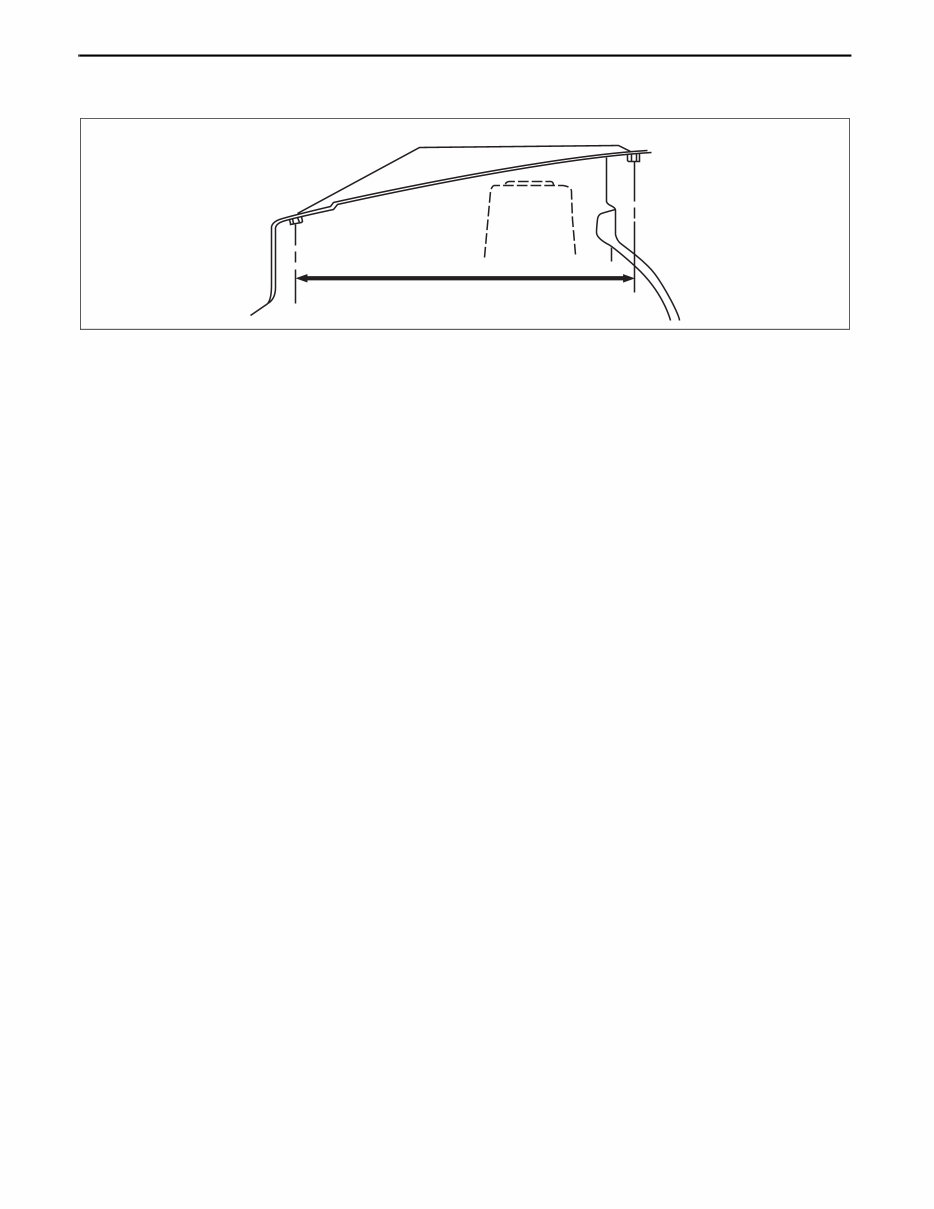
Body Dimensions (Flat-plane Dimensions)
• Flat-plane dimensions are the dimensions measured by projecting certain reference points onto a plane
surface.
• When there are no specific indications, the standard points and dimensions are symmetrical in regard to the
center of the vehicle.
• The hypothetical lines may differ according to the vehicle model.
• The schematic diagram shows the vehicle as it is projected from the underbody.
810 {31.89}
FLAT-PLANE DIMENSIONS
FRONT FENDER INSTALLATION NUT
am5ezb0000017
GENERAL INFORMATION
00-00–5
00-00
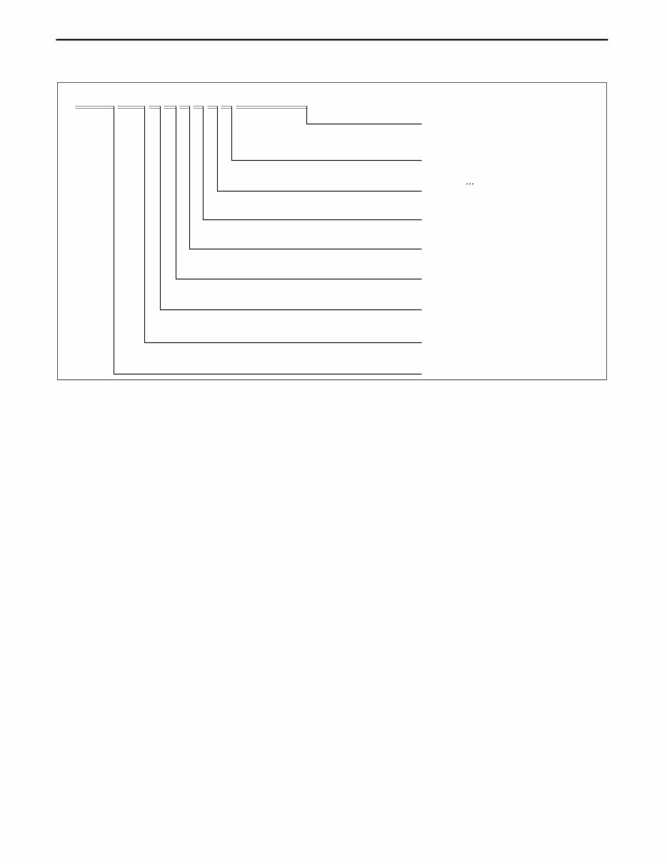
Example
Shows vehicle section
Shows outline drawing
Shows dimension
Shows point
symbol
Crossmember No,1 standard hole
Front side frame standard hole
Front suspension mounting
block surface hole center
Front suspension mounting bolt
Front frame rear standard hole
Front frame rear standard hole
Rear side frame standard hole
Link bracket
Rear suspension housing
A
B
C
D
E
F
G
H
I
J
K
Rear side frame standard hole
Rear side frame standard hole
Shows bolt size
Shows hole diameter
mm {in}
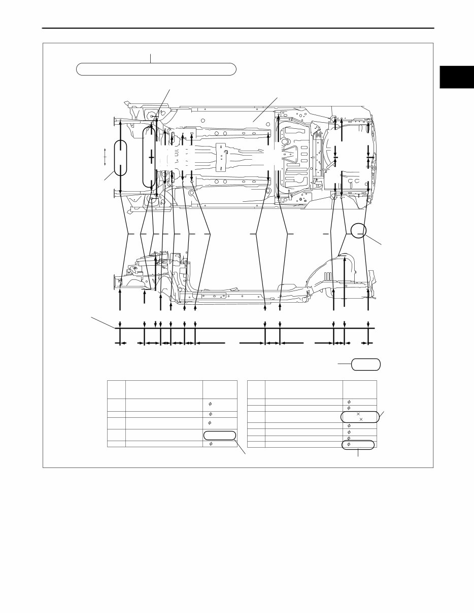
UNDERBODY FLAT-PLANE DIMENSIONS
16 {0.62}
16 {0.62}
16 {0.62}
M14 {0.55}
80 {3.14}
16 {0.62}
31 {1.22}
12 {0.47}
Rear suspension housing
L 12 {0.47}
16 {0.62}
18 {0.62}
17 29.5
{0.66 1.16}
A B C D E F G H I J K L
182 93 144 120
{7.17} {3.66} {5.67} {4.72}
140 68
{5.51} {2.68}
LH
RH
1,016
{40.00}
469
{18.46}
455
{17.91}
1,106 {43.54}
760 {29.92}
605 {23.82}
650 {25.59}
650 {25.59}
650 {25.59}
1,164 {45.83}
543
{21.37}
484
{19.05}
1,073 {37.91}
485
{19.1}
478
{18.8}
The dimensions on the left and
right in regard to the center of
the vehicle are different.
Shows hypothetical
standard line
When there are no specific indications, all of
units are in millimeters (mm).
Shows
slot
Designation
Point
symbol
Hole diameter
or bolt or nut
size mm {in}
Designation
Point
symbol
Hole diameter
or bolt or nut
size mm {in}
687
{27.05}
654
{25.75}
1,084 {42.84}
579
{22.80}
479
{18.86}
436
{17.17}
436
{17.17}
445
{17.52}
512
{20.16}
660
{25.98}
1,043
{41.06}
666
{26.22}
420
{16.54}
1,030
{40.55}
760
{29.92}
379
{14.92}
am5ezb0000017
GENERAL INFORMATION
00-00–6
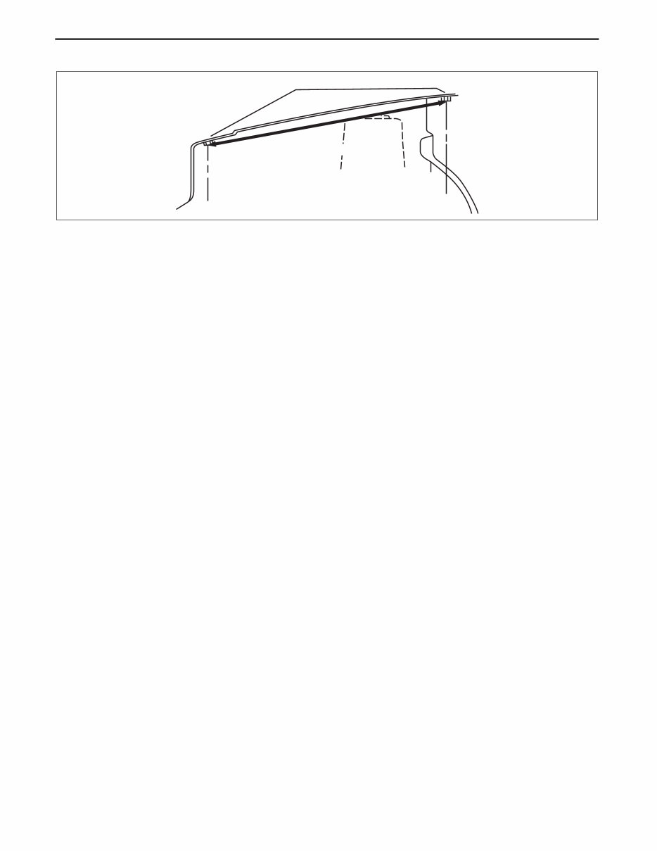
Body Dimensions (Straight-line Dimensions)
• Straight-line dimensions are the actual dimensions between two standard points.
• When there are no specific indications, the standard points and dimensions are symmetrical in regard to the
center of the vehicle.
817 {32.17}
FRONT FENDER INSTALLATION NUT
STRAIGHT-LINE DIMENSIONS
am5ezb0000017
GENERAL INFORMATION
00-00–7
00-00
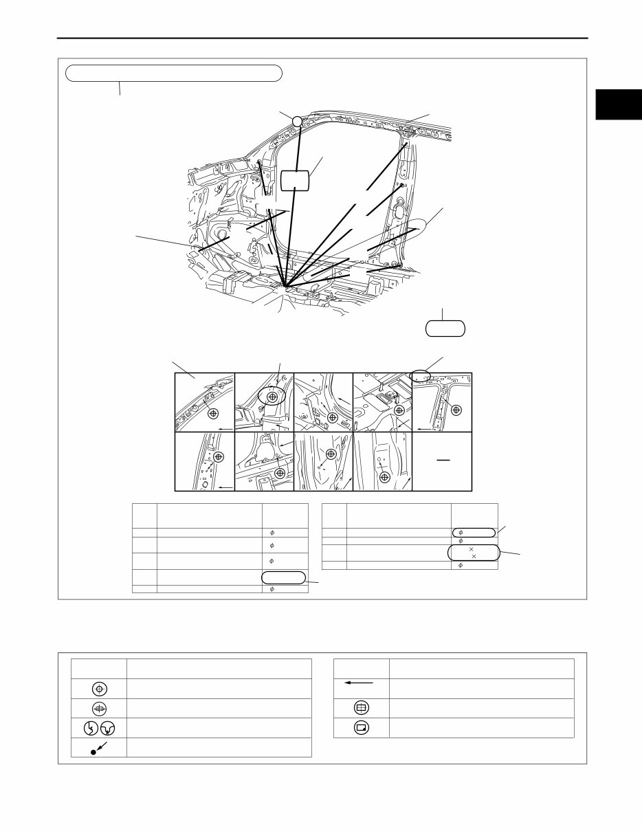
Example
Symbols of Body Dimensions
• The following 8 symbols are used to indicate the standard points.
End Of Sie
A
B
C
H
D
I
E
F
G
A
F
G
B
H
I
C
D
E,E'
Fr
Fr Fr
Fr Fr
Fr
Fr
Fr
Fr
Front pillar inner designation
Front pillar inner designation
Front floor pan designation
Adjuster installation hole
Trim installation hole
Harness installation hole
Chaker bracket installation hole
Chaker bracket installation hole
A
B
C
D
E
F
G
H
I
16 {0.62} 18 {0.71}
16 {0.62}
Harness installation hole
Designation
Shows bolt size
Shows hole diameter
Shows
slot
16 {0.62}
M14 {0.55}
31 {1.22}
17 {0.67}
12 {0.47}
1,128
{44.41}
1,263
{49.72}
1,048
{41.26}
1,406
{55.35}
851
{33.50}
1,067
{42.01}
799
{31.46}
1,398
{55.04}
Point
symbol
Hole diameter
or bolt or nut
size mm {in}
Designation
Point
symbol
Hole diameter
or bolt or nut
size mm {in}
17 29.5
{0.66 1.16}
ROOM STRAIGHT-LINE DIMENSIONS (1)
Shows vehicle section
Shows dimension location
Shows outline drawing
Shows position and shape of the points
Shows dimension
mm {in}
No indication are shown
within the outline drawing.
Shows point
symbol
When there are no specific indications, all of
units are in millimeters (mm).
Shows point indication
Without apostrophe:RH
With apostrophe:LH
Shows details of the standard
point location
am5ezb0000017
SYMBOL MEANING SYMBOL MEANING
Center of circular hole
Center elliptical hole
Notch
Panel seam, bead, etc.
Bolt tip
(arrow only)
Center of rectangular-shaped hole
Edge of rectangular-shaped hole
acxuub00000037
GENERAL INFORMATION
00-00–8
AIR BAG SYSTEM SERVICE WARNINGS
id000000920000
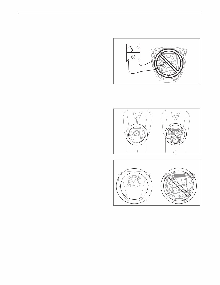
Air Bag Module Inspection
• Inspecting an air bag module using a tester can operate (deploy) the air bag module, which may cause
serious injury. Do not use a tester to inspect an air bag module. Always use the on-board diagnostic
function to diagnose the air bag module for malfunctions.
Air Bag Module Handling
• Before removing the air bag module or disconnecting the air bag module connector, always switch the
ignition to off, disconnect the negative battery cable, and then wait for 1 min or more to allow the
backup power supply of the SAS control module to deplete its stored power.
• Handling a live (undeployed) air bag module
that is pointed toward your body could result
in serious injury if the air bag module were to
accidentally operate (deploy). When carrying
a live (undeployed) air bag module, point the
deployment surface away from your body to
lessen the chance of injury in case it operates
(deploys).
• A live (undeployed) air bag module placed
with its deployment surface to ground is
dangerous. If the air bag module were to
accidentally operate (deploy), it could cause
serious injury. Always place a live
(undeployed) air bag module with its
deployment surface up.
Side Air Bag Module Handling
• Before removing the side air bag module or disconnecting the side air bag module connector, always
switch the ignition to off, disconnect the negative battery cable, and then wait for 1 min or more to
allow the backup power supply of the SAS control module to deplete its stored power.
• When a side air bag module operates (deploys) due to a collision, the interior of the seat back (pad,
frame, trim) may become damaged. If a side air bag does not operate (deploy) normally from a seat
back that has been reused, a serious accident may result. After a side air bag has operated (deployed),
always replace both the side air bag module and the seat back (pad, frame, trim) with new parts. After
servicing, verify that the seat operates normally and that the wiring harness is not caught.
NO GOOD
am3uuw0000368
GOOD NO GOOD
am3uuw0000368
NO GOOD GOOD
am3uuw0000369
You're Reading a Preview
What's Included?
Fast Download Speeds
Offline Viewing
Access Contents & Bookmarks
Full Search Facility
Print one or all pages of your manual
$35.99
Viewed 77 Times Today


Secure transaction
What's Included?
Fast Download Speeds
Offline Viewing
Access Contents & Bookmarks
Full Search Facility
Print one or all pages of your manual
$35.99
This manual is a comprehensive guide covering the Mazda 5 from 2012 to 2014, inclusive of both service and body manuals. It contains all the essential instructions required for vehicle repairs, from basic maintenance to extensive disassembly. Professional technicians and DIY enthusiasts alike can benefit from the accurate and concise text, accompanied by illustrations, which enable safe and straightforward servicing and repairs.
- Includes coverage for Mazda 5 2012, 2013, and 2014 models
- Encompasses service and body manuals
- Provides reliable information for routine maintenance and extensive repairs
- Comprehensive diagrams and in-depth illustrations
- Incorporates manufacturers' specifications and technical information
- Compatible with various operating systems: Windows (95, 98, ME, XP, 7), MAC, iPhone, iPad, iPod, LINUX


