

2005-2010 Mazda 5 Service & Repair Manual
What's Included?
Fast Download Speeds
Offline Viewing
Access Contents & Bookmarks
Full Search Facility
Print one or all pages of your manual


09–00–2
OUTLINE
BODY AND ACCESSORIES NEW FEATURES
DPE090000000T02
P/W CM Power Window Control Module
RH Right Hand
SW Switch
TNS Tail Number Side Lights
WDS Worldwide Diagnostic System
Improved marketability
• Power sliding door (PSD) adopted
• Auto-open/close function adopted for all power windows
• Power door lock system adopted
• Advanced keyless entry & start system adopted
• Hard disc drive (HDD) built-in audio system adopted
• Rear entertainment system (RES) adopted
• Hard-plastic liftgate adopted
Improved convenience
• Exterior open/close function adopted for power window
• IG OFF timer function adopted for power outer mirror
• Auto light system adopted
• Auto wiper system adopted
• Car-navigation system adopted
• Back monitor system adopted
Improved safety • Triple-H structure adopted
Improved security
• Immobilizer system adopted
• Theft-deterrent system adopted
Improved visibility
• Discharge headlight adopted
• Headlight auto leveling system adopted
Wiring harness simplification • Controller area network (CAN) system adopted
System simplification • Body control module adopted

BODY PANELS
09–10–1
09
09–10 BODY PANELS
BODY PANEL OUTLINE . . . . . . . . . . . . . 09–10–1
CABIN CONSTRUCTION . . . . . . . . . . . . 09–10–1
BUMPER CONSTRUCTION . . . . . . . . . . . 09–10–3
BODY PANEL OUTLINE
DPE091056100T01
• An H-shaped frame (triple-H structure) has been adopted.
• A highly rigid and safe body, "MAGMA” (Mazda Geometric Motion Absorption; Mazda’s all-direction impact
absorption body), has been adopted.
CABIN CONSTRUCTION
DPE091056100T03
• An impact dispersing three-fork structure that disperses a frontal impact into three directions has been
adopted.
• A crossbeam that suppresses the hinge pillars from moving outward during a collision has been adopted,
improving the cabin strength.
• A distribution of reinforcement to the floor, side frames, and roof employing an H-shaped structure to reinforce
each joint has been adopted. the combination of three points to each floor, side frames, and roof surface
provide the strong triple H-shaped structure.
1 Front bumper reinforcement
2 Collision energy
3 Front side frame
4 To side sill
5 To hinge pillar
6 Impact dispersing three-fork structure
7 To dash lower clossmember
8 Clossbeam
3
2
5
4
1
6
8
7
DPE910ZT1001


BODY PANELS
09–10–3
09
BUMPER CONSTRUCTION
DPE091056100T04
• Standard or sport type bumper is available.
STANDARD TYPE
SPORT TYPE
DPE910ZT1003

DOORS AND LIFTGATE
09–11–1
09
09–11 DOORS AND LIFTGATE
DOORS AND LIFTGATE OUTLINE . . . . 09–11–1
DOORS AND LIFTGATE STRUCTURAL
VIEW . . . . . . . . . . . . . . . . . . . . . . . . . . . 09–11–2
SIDE IMPACT BAR FUNCTION . . . . . . . 09–11–2
SIDE IMPACT BAR CONSTRUCTION/
OPERATION . . . . . . . . . . . . . . . . . . . . . 09–11–2
SLIDING DOOR CATCHER PIN
FUNCTION . . . . . . . . . . . . . . . . . . . . . . 09–11–3
SLIDING DOOR CATCHER PIN CONSTRUCTION/
OPERATION . . . . . . . . . . . . . . . . . . . . . 09–11–3
POWER SLIDING DOOR (PSD) SYSTEM
OUTLINE . . . . . . . . . . . . . . . . . . . . . . . . 09–11–3
POWER SLIDING DOOR (PSD) SYSTEM
STRUCTURAL VIEW . . . . . . . . . . . . . . 09–11–4
POWER SLIDING DOOR (PSD) SYSTEM SYSTEM
WIRING DIAGRAM . . . . . . . . . . . . . . . . 09–11–5
POWER SLIDING DOOR (PSD) SYSTEM
OPERATION . . . . . . . . . . . . . . . . . . . . . 09–11–6
PSD FRONT SWITCH CONSTRUCTION/
OPERATION . . . . . . . . . . . . . . . . . . . . . 09–11–7
POWER SLIDING DOOR (PSD) DRIVE UNIT
OUTLINE . . . . . . . . . . . . . . . . . . . . . . . . 09–11–7
POWER SLIDING DOOR (PSD) DRIVE UNIT
CONSTRUCTION/OPERATION . . . . . . 09–11–8
POWER SLIDING DOOR (PSD) CONTROL MODULE
FUNCTION . . . . . . . . . . . . . . . . . . . . . . 09–11–9
POWER SLIDING DOOR (PSD) CONTROL MODULE
CONSTRUCTION/OPERATION . . . . . . 09–11–10
LATCH RELEASE ACTUATOR CONSTRUCTION/
OPERATION . . . . . . . . . . . . . . . . . . . . . . 09–11–11
AUTO CLOSURE SYSTEM OUTLINE . . . 09–11–11
AUTO CLOSURE SYSTEM STRUCTURAL
VIEW . . . . . . . . . . . . . . . . . . . . . . . . . . . . 09–11–12
AUTO CLOSURE CONTROL MODULE
FUNCTION . . . . . . . . . . . . . . . . . . . . . . . 09–11–12
AUTO CLOSURE CONTROL MODULE
CONSTRUCTION/OPERATION . . . . . . . 09–11–12
AUTO CLOSURE MOTOR FUNCTION . . 09–11–12
AUTO CLOSURE MOTOR CONSTRUCTION/
OPERATION . . . . . . . . . . . . . . . . . . . . . . 09–11–12
LATCH POSITION SWITCH
FUNCTION . . . . . . . . . . . . . . . . . . . . . . . 09–11–13
LATCH POSITION SWITCH CONSTRUCTION/
OPERATION . . . . . . . . . . . . . . . . . . . . . . 09–11–13
AUTO CLOSURE MOTOR CONTROL FUNCTION
OUTLINE . . . . . . . . . . . . . . . . . . . . . . . . 09–11–13
AUTO CLOSURE MOTOR CONTROL FUNCTION
SYSTEM WIRING DIAGRAM . . . . . . . . . 09–11–14
AUTO CLOSURE MOTOR CONTROL FUNCTION
OPERATION . . . . . . . . . . . . . . . . . . . . . . 09–11–15
FAIL-SAFE FUNCTION OUTLINE . . . . . . 09–11–17
FAIL-SAFE FUNCTION OPERATION . . . 09–11–17
LOCK MECHANISM OUTLINE . . . . . . . . 09–11–17
LOCK MECHANISM CONSTRUCTION/
OPERATION . . . . . . . . . . . . . . . . . . . . . . 09–11–17
OPEN LOCK ACTUATOR CONSTRUCTION/
OPERATION . . . . . . . . . . . . . . . . . . . . . . 09–11–19
DOORS AND LIFTGATE OUTLINE
DPE091158010T01
Features
Improved marketability • A power sliding door (PSD) system, which allows the sliding doors to open/close automatically,
has been adopted for both LH and RH sliding doors.
• An auto closure system that assists the sliding doors to close securely when they are ajar has
been adopted. (vehicles with PSD)
• A constant power supply wiring harness which supplies power while the sliding door is open has
been adopted.
• Door modules with integrated front door/sliding door internal parts have been adopted.
• A light-weight hard plastic liftgate has been adopted to reduce opening/closing operation force.
Improved safety • A rigid side impact bar has been adopted for each front door and sliding door.
• A sliding door catcher pin has been adopted.
• An open-lock function which keeps the sliding door open has been adopted.
Vehicle damage
prevention
• A sliding door open cancel system has been adopted to the right side of the vehicle.
09–11–2
DOORS AND LIFTGATE
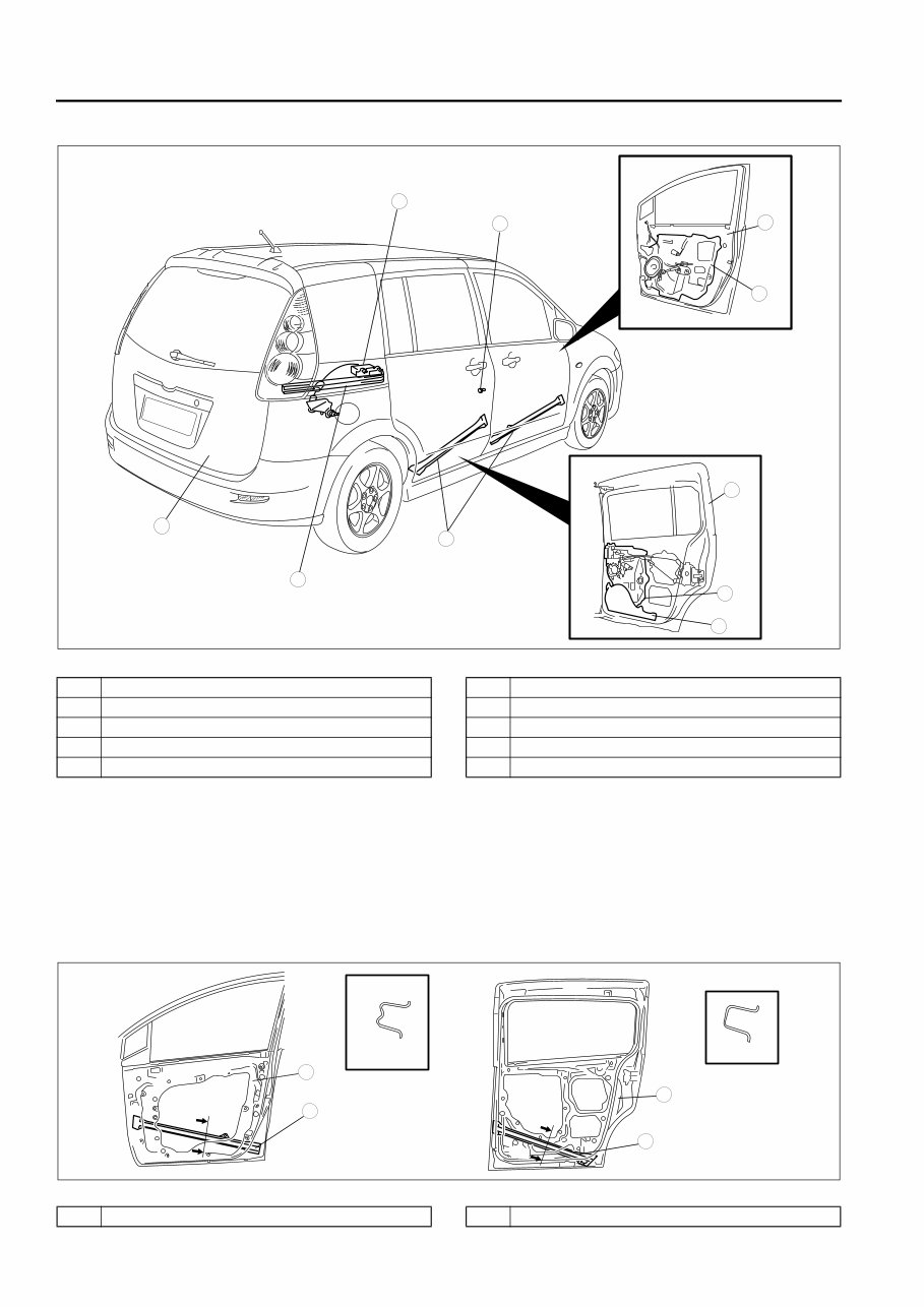
DOORS AND LIFTGATE STRUCTURAL VIEW
DPE091158010T02
SIDE IMPACT BAR FUNCTION
DPE091158010T03
• The side impact bar, located on the bottom part of the door, prevents the door from deforming inward by
dispersing the impact to the floor in case of a side-impact collision.
• A corrugated side impact bar has been adopted to each front door, improving rigidity in case of a collision.
SIDE IMPACT BAR CONSTRUCTION/OPERATION
DPE091158010T04
• Installed to the inside of the door.
9
8
7
5
4
3
10
6
1
2
DPE911ZN1001
1 Front door
2 Sliding door
3 Front door unit
4 Sliding door unit
5 Constant power supply wiring harness
6 Liftgate
7 Sliding door catcher pin
8 sliding door open stopper
9 Side impact bar
10 Center guide rail
SEC. A—A
A
A
SEC. B—B
B
B
3
1
2
3
DPE911ZN1002
1 Front door 2 Sliding door

DOORS AND LIFTGATE
09–11–3
09
SLIDING DOOR CATCHER PIN FUNCTION
DPE091158010T05
• Prevents the sliding door from deforming inward toward the cabin during a side collision.
SLIDING DOOR CATCHER PIN CONSTRUCTION/OPERATION
DPE091158010T06
• Installed to the B-pillar.
• When the sliding door is fully closed, the sliding door catcher pin is inserted into the sliding door. If the vehicle
is subjected to a side impact with the pin inserted, the sliding door contacts the sliding door catcher pin and is
stopped.
POWER SLIDING DOOR (PSD) SYSTEM OUTLINE
DPE091158010T22
• A power sliding door (PSD) system, which allows the sliding doors to open/close automatically, has been
adopted for both LH and RH sliding doors.
• The sliding doors open/close automatically by the following switches and buttons:
• When any of the following switches or buttons are pressed while the door is sliding, the door is stopped. (To
stop a door, a switch or a button for the corresponding door should be pressed.)
— PSD front OPEN/CLOSE switch
— PSD OFF switch
— Inner handle
— Outer handle
— Transmitter R or L button
• Using the PSD OFF switch, operation of the sliding doors can be switched between power and manual sliding.
• When each switch is operated, the buzzer sounds for 0.5 seconds to indicate that a sliding door is starting to
3 Side impact bar
A
A
SEC. A—A
5
4
3
1
2
1
2
4
3
DPE911ZN1003
1 Sliding door catcher pin
2 Sliding door
3 Inside of vehicle
4 Outside of vehicle
5 Collision energy
Switch and button
Sliding door position
Fully closed Partly open Fully open
PSD front OPEN switch Open Open Not operation
PSD front CLOSE switch Not operation Close Close
Inner handle close direction (tilt forward) Not operation Close Close
Inner handle open direction (tilt rearward) Open Open Not operation
Outer handle Open Open Close
Transmitter R or L button Open Open Close
09–11–4
DOORS AND LIFTGATE
open/close.
• When a sliding door contacts an obstruction during opening/closing operation, the door reverses direction
automatically to prevent jamming.
• When the sliding door comes to the position before the fully closed position during the close operation, the
sliding speed is slowed to ensure safety.
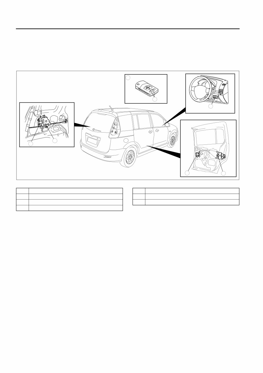
POWER SLIDING DOOR (PSD) SYSTEM STRUCTURAL VIEW
DPE091158010T23
L
R
7
5
4
3
1
2
6
DPE911ZN1017
1 PSD control module
2 PSD drive unit
3 Vehicles with keyless entry system
4 PSD R/L button (transmitter)
5 PSD front switch
6 Latch release actuator
7 Auto closure motor

You're Reading a Preview
What's Included?
Fast Download Speeds
Offline Viewing
Access Contents & Bookmarks
Full Search Facility
Print one or all pages of your manual
$31.99
Viewed 68 Times Today


Secure transaction
What's Included?
Fast Download Speeds
Offline Viewing
Access Contents & Bookmarks
Full Search Facility
Print one or all pages of your manual
$31.99
Get instant access to the Complete Factory Service Repair Workshop Manual without any extra fees or expiry dates. This Professional Manual is suitable for your computer, tablet, or smartphone and covers all repairs, servicing, and troubleshooting procedures. It contains detailed photos, diagrams, step-by-step instructions, and highly detailed exploded diagrams and pictures, making it useful for both professional Mechanics and DIY enthusiasts.
Print out a single page or the entire manual as per your preference. This Manual can be used on multiple computers without any limitations or trial periods and can be used for life without the need for renewal or extra payment. It is fully compatible with all Windows and MAC Computers.


