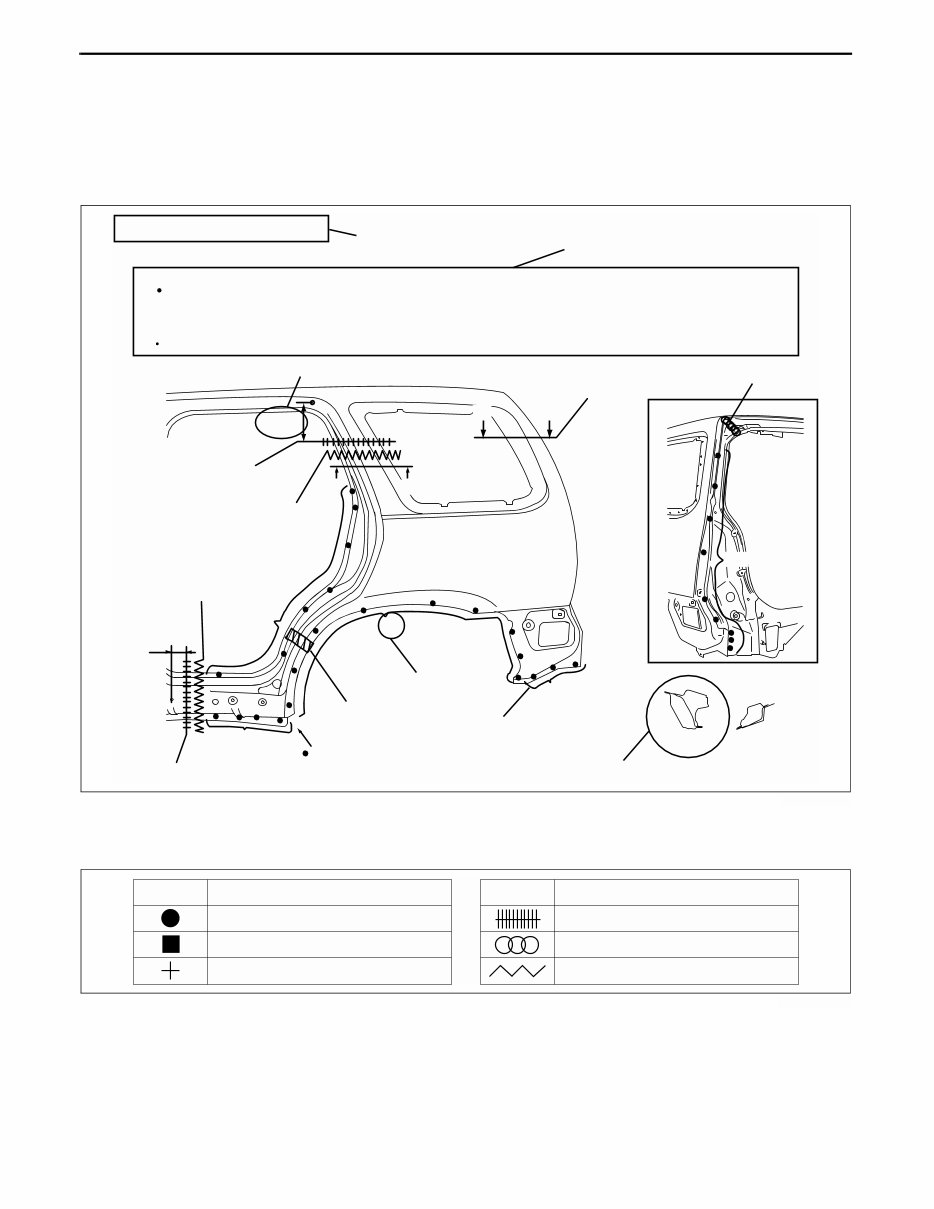
GENERAL INFORMATION 00–00–2 HOW TO USE THIS MANUAL C3U000000000B01 Efficient Replacement of Body Panels • This section contains information on the body panels in regard to the welding types, number of spot welds, and cut-and-join locations that are necessary for panel removal and installation. • The type of weld and position are indicated by symbols. • Some sections have notes concerning the operation being performed. Thoroughly read and understand the notes before carrying out any procedures. Example Symbols of Panel Replacement • The following 6 symbols are used to indicate the type of weld that is used when replacing body panels. REAR FENDER PANEL REMOVAL Shows operation section Shows procedure, caution and note BRAZE WELDING CUT-AND-JOINT LOCATION CUT-AND-JOINT LOCATION ROUGH CUT LOCATION ROUGH CUT LOCATION Shows number of weld Shows welding region Shows a cross Shows a insulator Shows a dimensions Shows a cross location Avoid cutting with a flame as the insulator (shaded) is flammable. 1.The rear fender panel and wheel house are joined with glue at the wheel arch line. Drill the 24 weld locations indicated by (A), from the room side. Caution NOTE BOTTOM SIDE 1 {9.84in} 250mm (A)24 19 17 A-A A A B-B 30mm B B {1.18in} 8 4 MZZ2010B001 SYMBOL MEANING Spot welding CO 2 arc welding (plug welding) CO 2 spot welding SYMBOL MEANING Continuous MIG welding (Cut-and-join location) Braze welding Rough cut location MZZ2010B002
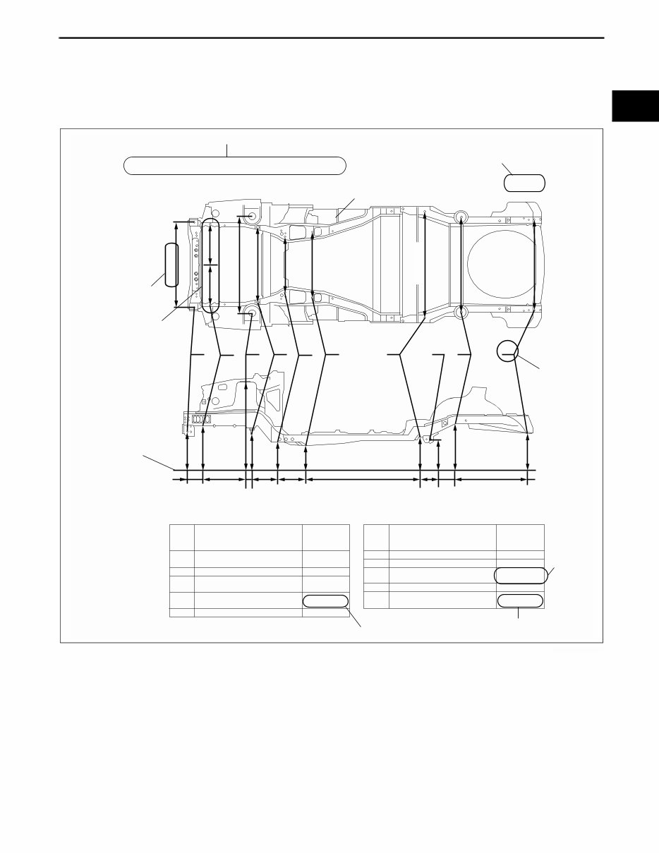
GENERAL INFORMATION 00–00–3 00–00 Body Dimensions (Flat-plane Dimensions) • Flat-plane dimensions are the dimensions measured by projecting certain reference points onto a plane surface. • When there are no specific indications, the standard points and dimensions are symmetrical in regard to the center of the vehicle. • The hypothetical lines may differ according to the vehicle model. Example Shows vehicle section When there are no specific indications, all of units are in millimeters (mm). Shows outline drawing Shows dimension The dimensions on the left and right in regard to the center of the vehicle are different. Shows hypothetical standard line Shows point symbol Point symbol Designation Hole diameter or bolt or nut size mm {in} 1,030 {40.55} 1,162 {45.78} 918 {38.14} 690 {27.17} 800 {31.50} 1,089 {42.87} 1,060 {41.73} 495 {19.48} 485 {19.09} 619 {24.38} 725 {28.55} 1,211 {47.68} 609 {24.00} 527 {20.75} 487 {19.19} 587 {23.11} 547 {21.54} 624 {24.56} 700 {27.58} 716 {28.21} 1,240 {48.82} 320 {12.62} 55 {2.19} 185 {7.28} 98 {3.86} 425 {16.73} 315 {12.40} 489 {19.27} A Crossmember No,1 standard hole B Front side frame standard hole C Front suspension mounting block surface hole center D Front suspension mounting bolt E Front frame rear standard hole F Front frame rear standard hole G Rear side frame standard hole H Link bracket I Rear suspension housing J A B C D E F G H I J Rear side frame standard hole Shows bolt size Shows hole diameter Shows slot mm {in} UNDERBODY FLAT-PLANE DIMENSIONS φ 16 {0.62} φ 16 {0.62} φ 16 {0.62} M14 {0.55} φ 80 {3.14} Point symbol Designation Hole diameter or bolt or nut size mm {in} φ 16 {0.62} φ 12 {0.47} φ 16 {0.62} φ 18 {0.62} 17 × 29.5 {0.66×1.16} 1,220 {48.03} MZZ2010B003
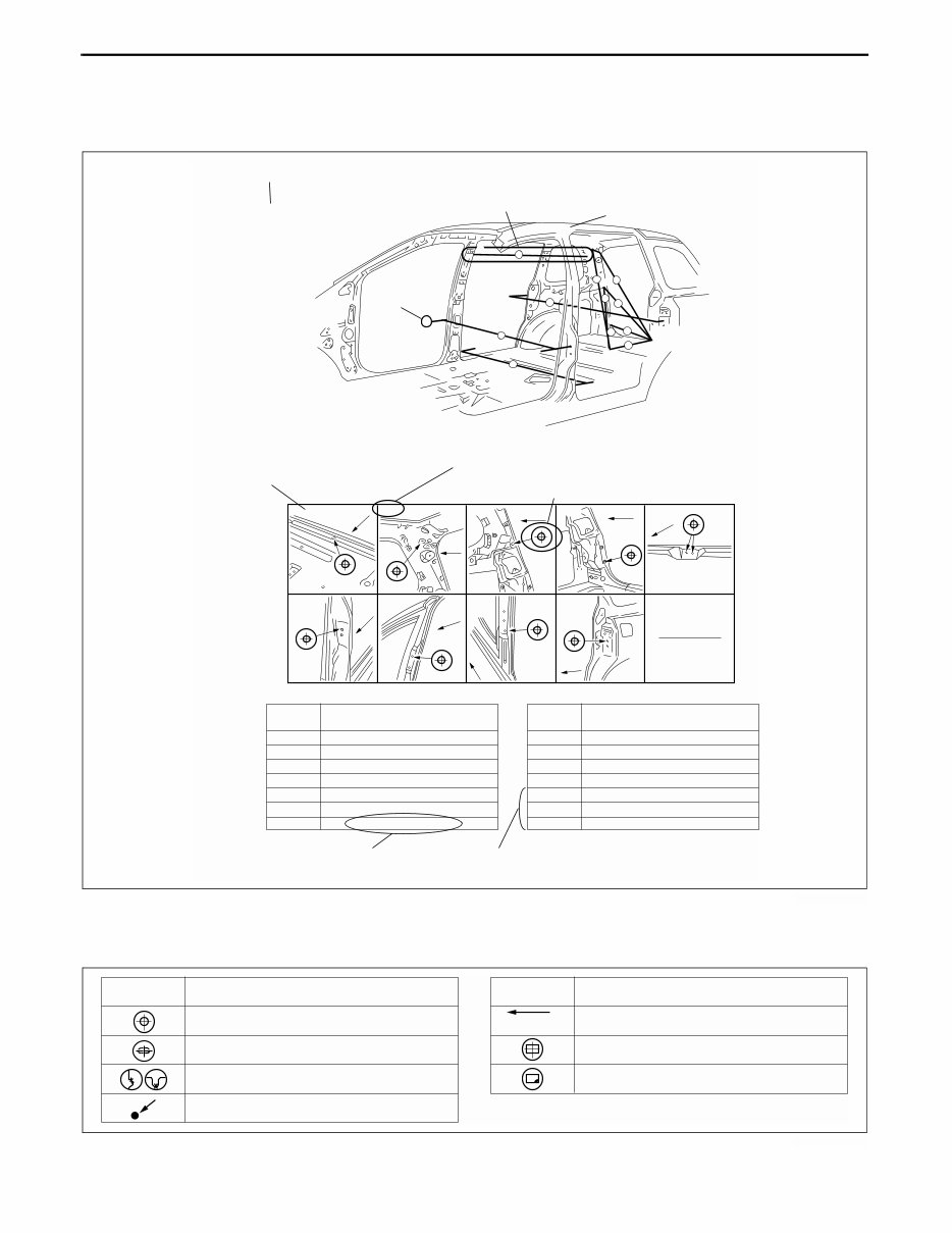
GENERAL INFORMATION 00–00–4 Body Dimensions (Straight-line Dimensions) • Straight-line dimensions are the actual dimensions between two standard points. • When there are no specific indications, the standard points and dimensions are symmetrical in regard to the center of the vehicle. Example Symbols of Body Dimensions • The following 8 symbols are used to indicate the standard points. End Of Sie ROOM STRAIGHT-LINE DIMENSIONS (2) Shows vehicle section Shows dimension location Shows outline drawing C D A G Shows point symbol Shows point indication Without apostrophe:RH With apostrophe:LH Shows details of the standard point location Shows position and shape of the points Shows dimension No indication are shown within the outline drawing. A Fr Fr Fr Fr Fr Fr Fr Fr Fr Measured location Dimension mm {in} 1 2 3 4 5 6 7 1,184 {46.61} 1,064 {41.89} 919 {36.18} 690 {27.17} 1,185 {46.65} 901 {35,47} 607 {23.90} Measured location Dimension mm {in} 8 9 10 11 B-B' C-C' D-D' 1,667 {65.63} 1,672 {65.83} 1,037 {40.83} 1,290 {50.79} 1,208 {47.56} 1,463 {57.60} 1,642 {64.65} B-B , C-C , D-D , H-H , G-G , F-F , E-E , H , E. E , H I B F , I - I , 1 5 6 9 7 3 2 4 8 F 11 10 MZZ2010B004 SYMBOL MEANING SYMBOL MEANING Center of circular hole Center elliptical hole Notch Panel seam, bead, etc. Bolt tip (arrow only) Center of rectangular-shaped hole Edge of rectangular-shaped hole MZZ2010B016
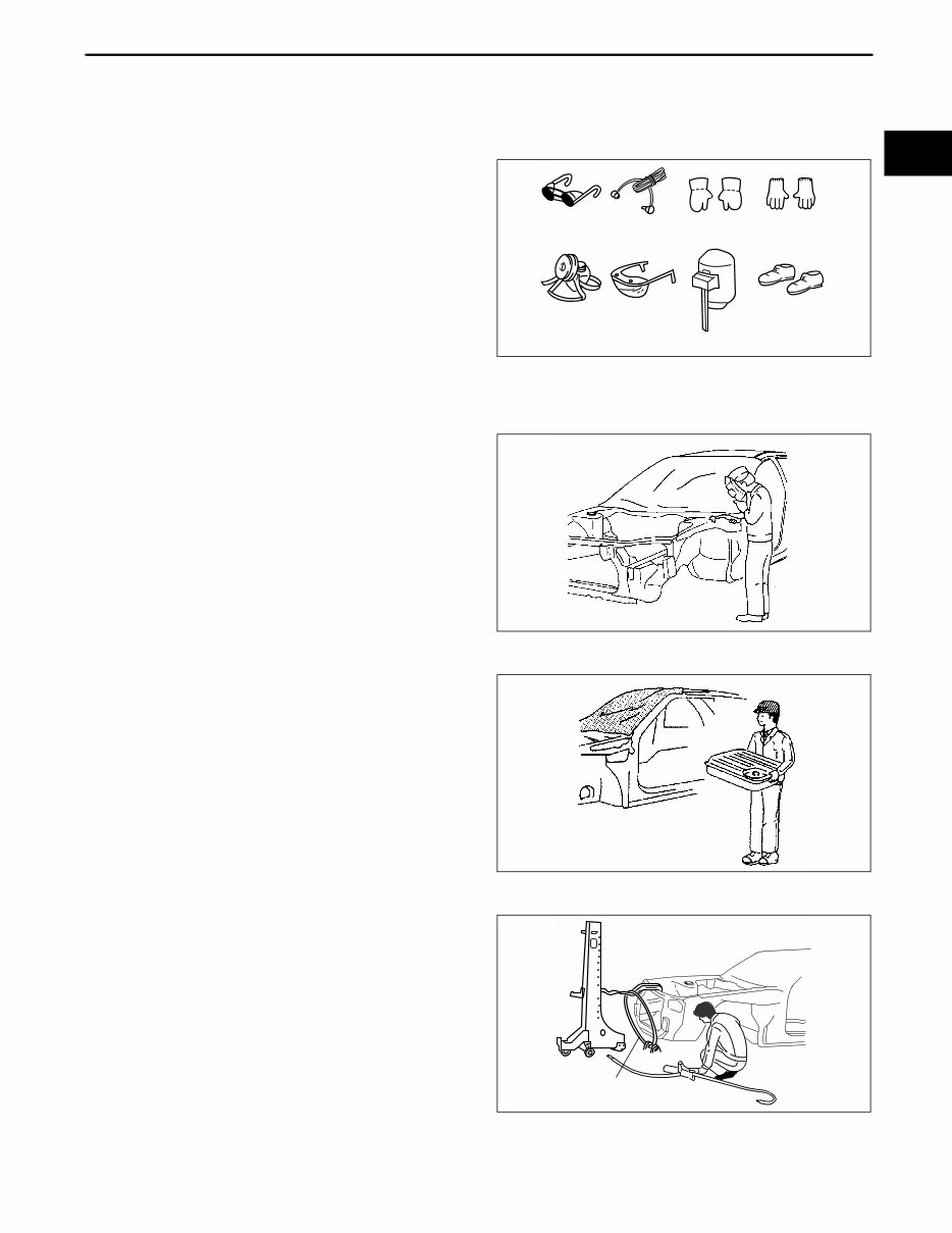
GENERAL INFORMATION 00–00–5 00–00 SERVICE PRECAUTIONS C3U000000000B02 Arrangement of Workshop • Arrangement of the workshop is important for safe and efficient work. Safety Precautions • Protective head covering and safety shoes should always be worn. Depending upon the nature of the work, gloves, safety glasses, ear protectors, face shield, etc., should also be used. Vehicle Protection • Use seat covers and floor covers. • Use heat-resistant protective covers to protect glass areas and seats from heat or sparks during welding. • Protect items such as moldings, garnishes, and ornaments with tape when welding. Remove Dangerous Articles • Remove the fuel tank before using an open flame in that area. Plug connection piping to prevent fuel leakage. Use of Pulling Equipment • When using pulling equipment, keep away from the pulling area and use safety wires to prevent accidents. Welding glasses Ear protectors Weldlng gloves Cotton gloves Dust mask Safety glasses Face shield Safety shoes MZZ2036B001 MZZ2036B002 MZZ2036B003 Safety wires MZZ2036B004
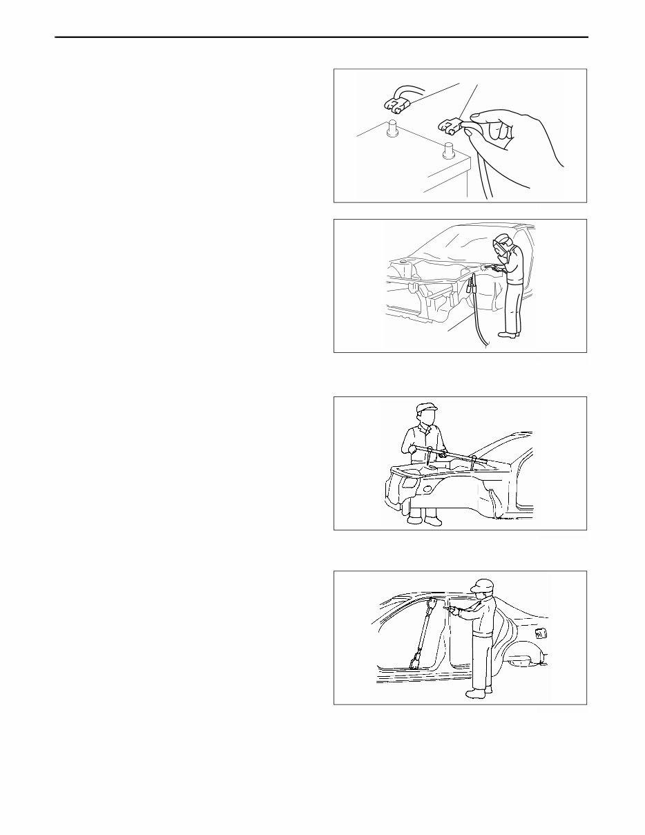
GENERAL INFORMATION 00–00–6 Prevent Short Circuits • Turn the ignition switch to the LOCK position. • Disconnect the battery cables. • Securely connect the welding machine ground near the welding area. End Of Sie EFFICIENT REMOVAL OF BODY PANELS C3U000000000B03 Body Measurements • Before removal or rough-cutting, first measure the body at and around the damaged area against the standard reference dimension specifications. If there is deformation, use frame repair equipment to make a rough correction. Prevention of Body Deformation • Use a clamp or a jack for removal and reinforce at and around the rough-cutting location to prevent deforming of the body. Battery cable MZZ2036B005 Ground MZZ2036B006 MZJ2038B001 MZJ2038B002
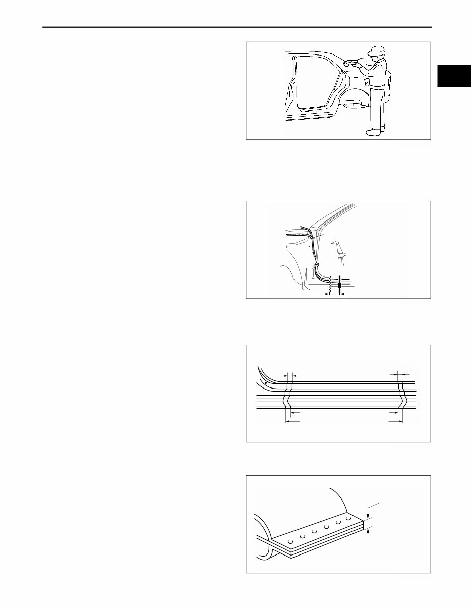
GENERAL INFORMATION 00–00–7 00–00 Selection of Cut-and-join Locations • For parts where complete replacement is not feasible, careful cutting and joining operations should be followed. If the location to be cut is a flat area where there is no reinforcement, the selected cutting location should be where the welding distortion will be minimal. Removal of Associated Parts • Protect moldings, garnishes, and ornaments with tape when removing associated parts. Rough Cutting of Damaged Panel • Verify that there are no parts (such as pipes, hoses, and wiring harness) nearby or on the opposite side of a panel which could be damaged by heat. • For cut-and-join areas, allow for an overlap of 30—50 mm {1.18—1.97 in} and then rough-cut the damaged panel. End Of Sie INSTALLATION PREPARATIONS C3U000000000B04 Rough Cutting of New Parts • For cut-and-join areas, allow for an overlap of 30—50 mm {1.18—1.97 in} with the remaining area on the body side and then rough-cut the new parts. Determination of Welding Method • If the total thickness at the area to be welded is 3 mm {0.12 in} or more, use a CO 2 gas shielded-arc welder to make the plug welds. MZJ2038B003 Wiring harness Rough cut location Cut-and-join location MZZ2038B001 Over lap Over lap Body side rough cut location New part rough cut location 30-50mm{1.18-1.97in} 30-50mm{1.18-1.97in} MZZ2038B002 3mm {0.12in}or more MZZ2038B003
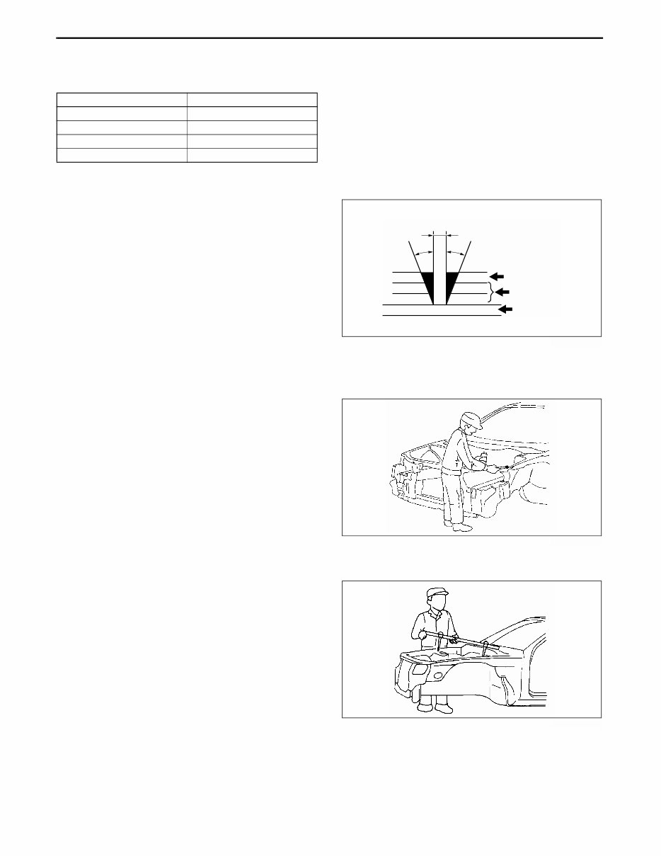
GENERAL INFORMATION 00–00–8 Making Holes for CO 2 Arc Welding • For places that cannot be spot welded, make a hole for CO 2 arc welding using a punch or drill as follows. (mm {in}) • Grind the shaded section indicated in the diagram below and create a hole in the part where the 3—4 plates are put together. Also, weld the plates together tightly so that gaps do not develop. Application of Weld-through Primer • For treatment against corrosion, remove the paint grease, and other material from the portion of new part and body to be welded, and apply weld-through primer. End Of Sie EFFICIENT INSTALLATION OF BODY PANELS C3U000000000B05 Checking Preweld Measurements And Watching • Align to the standard reference dimensions, based upon the body dimensions illustration, so that new parts are installed in the correct position. Panel thickness (ø) Hole diameter (ø) 0.60—0.90 {0.02—0.03} 5 {0.19} 0.91—1.20 {0.04—0.05} 6 {0.23} 1.21—1.80 {0.051—0.07} 8 {0.31} 1.81—4.50 {0.071—0.17} 10 {0.39} φ10mm{0.39in} Outer panel Middie panel Inner panel 30° 30° MZZ2038B004 MZJ2038B008 MZJ2038B009
This manual is a comprehensive guide for the Mazda 3 Body Shop 2004-2009, offering technical details directly from the manufacturer. It is a valuable resource for both professional mechanics and DIY enthusiasts, providing complete information on maintenance and repairs.
Containing mechanical and technical specifications, introductory mechanics, equipment elevation, collision details, product and supply information, painting, and descriptions of various vehicle parts, this manual equips you with step-by-step instructions, diagrams, and pictures for assembly, disassembly, cleaning, repairing, and maintenance.
Accessible immediately, this manual eliminates the need to wait for printed copies and offers an eco-friendly alternative to traditional books. Whether you seek specific details or general guidance, this manual is designed to meet your needs and provide high-quality solutions.
With this manual, you can access a wealth of information without delay, making it a convenient and cost-effective choice for obtaining the knowledge required to maintain and repair the Mazda 3 Body Shop 2004-2009.
Recently Viewed
5,521,897Happy Clients
2,594,462eManuals
1,120,453Trusted Sellers
15Years in Business
Price:
Actual Price:
2004-2009 Mazda 3 Body Shop Service & Repair Manual