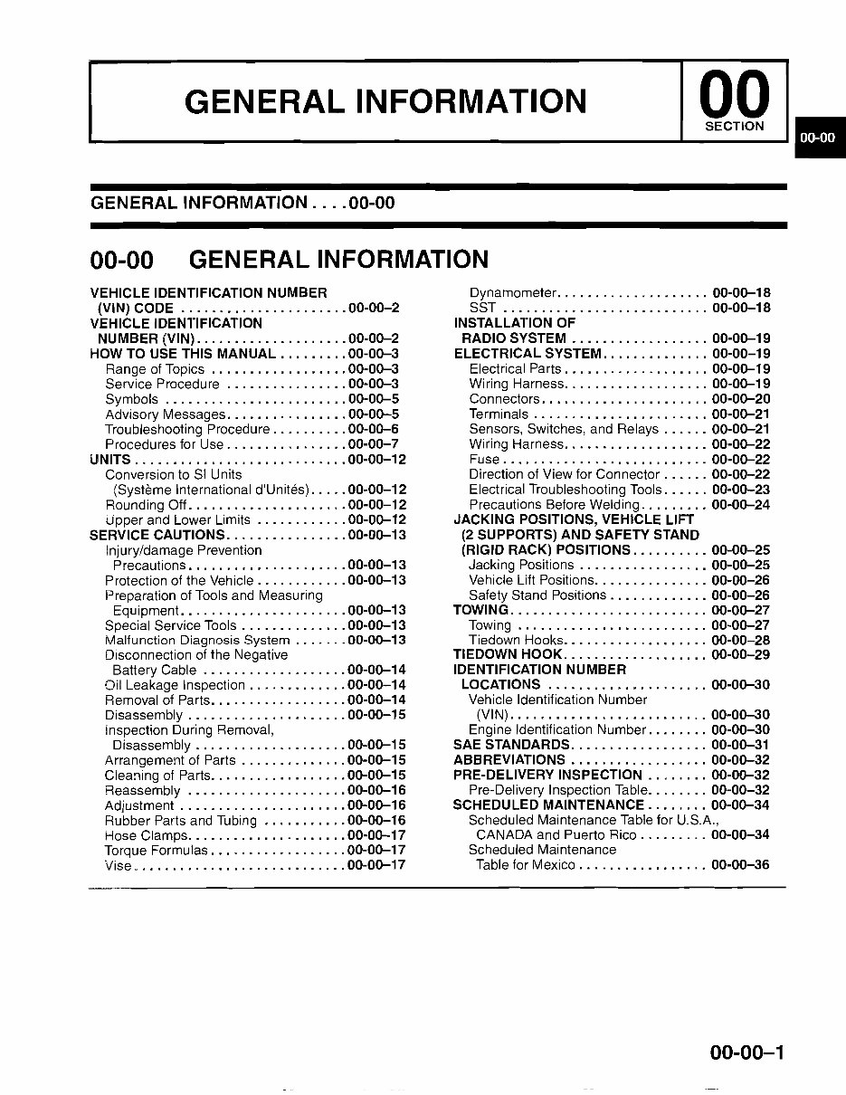
~~G_E_NE_R_A_L_IN_F_O_R_M_AT_I_ON~~I~I~ GENERAL INFORMATION .... 00-00 00-00 GENERAL INFORMATION VEHICLE IDENTIFICATION NUMBER Dynamometer 00-00-18 (VIN) CODE 00-00-2 SST 00-00-18 VEHICLE IDENTIFICATION INSTALLATION OF NUMBER (VIN) 00-00-2 RADIO SySTEM '" 00-00-19 HOW TO USE THIS MANUAL 00-00-3 ELECTRICAL SYSTEM 00-00-19 Range of Topics 00-00-3 Electrical Parts 00-00-19 Service Procedure 00-00-3 Wiring Harness 00-00-19 Symbols 00-00-5 Connectors 00-00-20 Advisory Messages 00-00-5 Terminals 00-00-21 Troubleshooting Procedure 00-00-6 Sensors, Switches, and Relays 00-00-21 Procedures for Use 00-00-7 Wiring Harness 00-00-22 UNITS 00-00-12 Fuse 00-00-22 Conversion to SI Units Direction of View for Connector 00-00-22 (Systeme International d'Unites) 00-00-12 Electrical Troubleshooting Tools 00-00-23 Rounding Oft. 00-00-12 Precautions Before Welding 00-00-24 Upper and Lower Limits 00-00-12 JACKING POSITIONS, VEHICLE LIFT SERVICE CAUTIONS 00-00-13 (2 SUPPORTS) AND SAFETY STAND Injury/damage Prevention (RIGID RACK) POSITIONS 00-00-25 Precautions 00-00-13 Jacking Positions 00-00-25 Protection of the Vehicle 00-00-13 Vehicle Lift Positions 00-00-26 Preparation of Tools and Measuring Safety Stand Positions 00-00-26 Equipment. 00-00-13 TOWING 00-00-27 Special Service Tools 00-00-13 Towing 00-00-27 Malfunction Diagnosis System 00-00-13 Tiedown Hooks 00-00-28 Disconnection of the Negative TIEDOWN HOOK 00-00-29 Battery Cable 00-00-14 IDENTIFICATION NUMBER Oil Leakage Inspection 00-00-14 LOCATIONS 00-00-30 Removal of Parts 00-00-14 Vehicle Identification Number Disassembly 00-00-15 (VIN) 00-00-30 inspection During Removal, Engine Identification Number 00-00-30 Disassembly 00-00-15 SAE STANDARDS 00-00-31 Arrangement of Parts 00-00-15 ABBREVIATIONS 00-00-32 Cleaning of Parts 00-00-15 PRE-DELIVERY INSPECTION 00-00-32 Reassembly 00-00-16 Pre-Delivery Inspection Table 00-00-32 Adjustment 00-00-16 SCHEDULED MAINTENANCE 00-00-34 Rubber Parts and Tubing 00-00-16 Scheduled Maintenance Table for U.S.A., Hose Clamps 00-00-17 CANADA and Puerto Rico 00-00-34 Torque Formulas 00-00-17 Scheduled Maintenance Vise 00-00-17 Table for Mexico 00-00-36 00-00-1
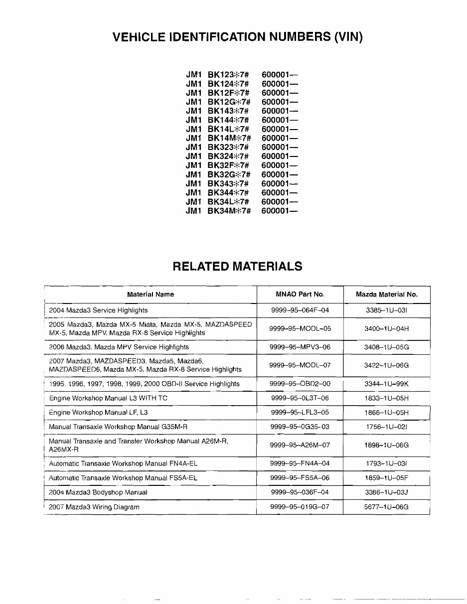
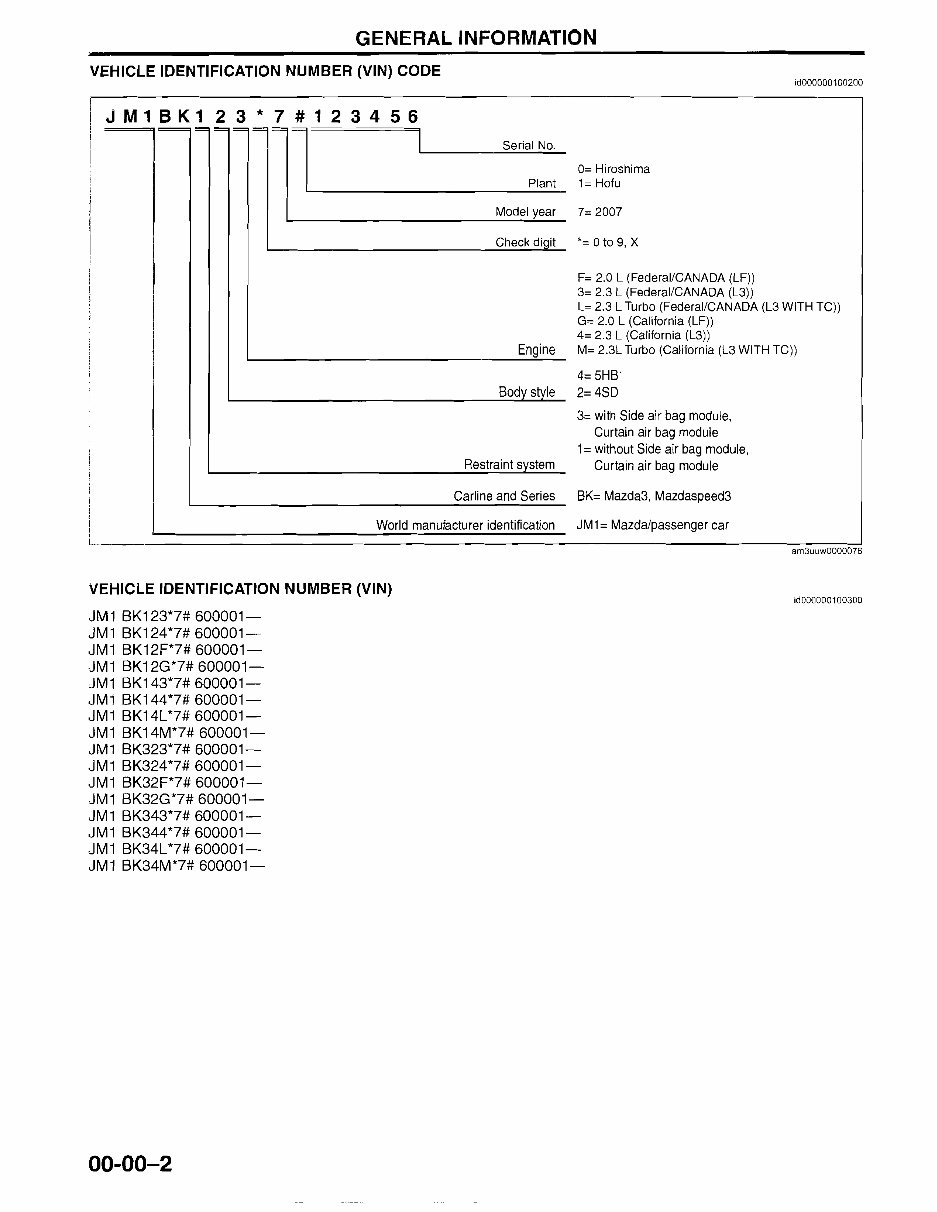
GENERAL INFORMATION VEHICLE IDENTIFICATION NUMBER (VIN) CODE id000000100200 JM1BK123*7#123456 '~~~~~'~l Serial No. I Plant Model year Check diqit Engine Body style Restraint system Carline and Series World manufacturer identification 0= Hiroshima 1= Hofu 7= 2007 *= 0 to 9, X F= 2.0 L (Federal/CANADA (LF)) 3= 2.3 L (Federal/CANADA (L3)) L= 2.3 L Turbo (Federal/CANADA (L3 WITH TC)) G= 2.0 L (California (LF)) 4= 2.3 L (California (L3)) M= 2.3L Turbo (California (L3 WITH TC)) 4= 5HB 2= 4SD 3= with Side air bag module, Curtain air bag module 1 = without Side air bag module, Curtain air bag module BK= Mazda3, Mazdaspeed3 J M1= Mazdalpassenger car VEHICLE IDENTIFICATION NUMBER (VIN) JM1 BK123*7# 600001- JM1 BK124*7# 600001- JM1 BK12F*7# 600001- JM1 BK12G*7# 600001- JM1 BK143*7# 600001- JM1 BK144*7# 600001- JM 1 BK14L*7# 600001- JM1 BK14M*7# 600001- JM1 BK323*7# 600001- JM1 BK324*7# 600001- JM1 BK32F*7# 600001- JM1 BK32G*7# 600001- JM1 BK343*7# 600001- JM1 BK344*7# 600001- JM1 BK34L*7# 600001- JM1 BK34M*7# 600001- am3uuw0000076 id000000100300 00-00-2
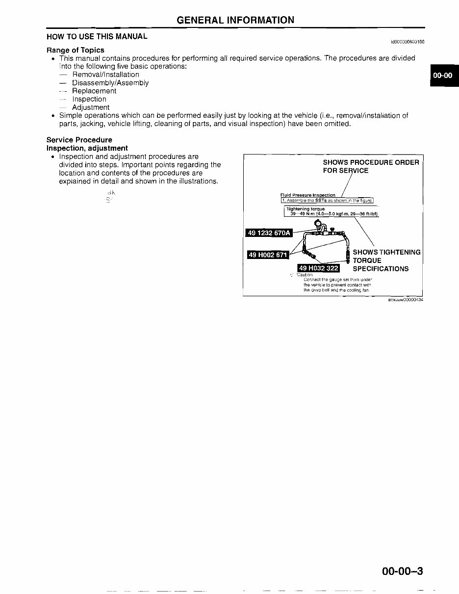
GENERAL INFORMATION HOW TO USE THIS MANUAL Range of Topics id000000800100 • This manual contains procedures for performing all required service operations. The procedures are divided into the following five basic operations: Removal/I nstallation Disassembly/Assembly Replacement • Inspection Adjustment • Simple operations which can be performed easily just by looking at the vehicle (i.e., removal/installation of parts, jacking, vehicle lifting, cleaning of parts, and visual inspection) have been omitted. Service Procedure Inspection, adjustment • Inspection and adjustment procedures are SHOWS PROCEDURE ORDER divided into steps. Important points regarding the FOR SERVICE location and contents of the procedures are explained in detail and shown in the illustrations. SHOWS TIGHTENING TORQUE SPECIFICATIONS ~. 'Caution Connect the gauge set from under the vehicie to prevent contact with the drive belt and the cooling fan. acxuuw00000434 00-00-3
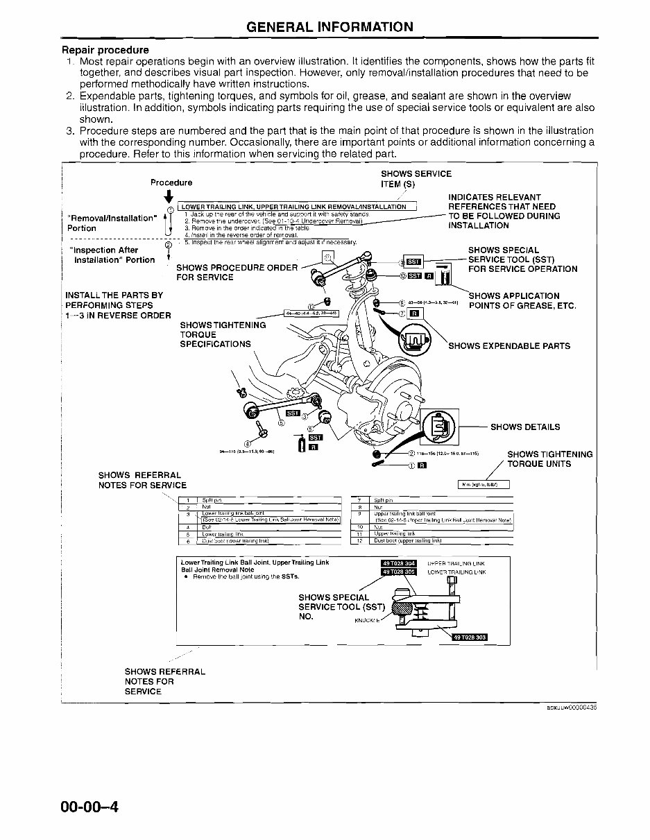
GENERAL INFORMATION Repair procedure 1. Most repair operations begin with an overview illustration. It identifies the components, shows how the parts fit together, and describes visual part inspection. However, only removal/installation procedures that need to be performed methodically have written instructions. 2. Expendable parts, tightening torques, and symbols for oil, grease, and sealant are shown in the overview illustration. In addition, symbols indicating parts requiring the use of special service tools or equivalent are also shown. 3. Procedure steps are numbered and the part that is the main point of that procedure is shown in the illustration with the corresponding number. Occasionally, there are important points or additional information concerning a procedure. Refer to this information when servicing the related part. SHOWS SERVICE Procedure ITEM (S) ... / INDICATES RELEVANT I LOWER TRAILING LINK, UPPER TRAILING LINK REMOVAUINSTALLATION I REFERENCES THAT NEED "R III t II t'" 1.JaCkup therearotthevehlclea.ndsu pp ort. it with safely stands. __--- TO BE FOLLOWED DURING emova ns a a Ion 2. Remove the undercover (See 01-10-4 Undercover Removal Portion 3. Remove in the order indicated ,n the table INSTALLATION U 4. Install in the reverse order of removal. ---- _.- ---------------- -~-.- ~ 5. Inspect the rear wheel alignment and adjust it if necessary. SHOWS TIGHTENING TORQUE UNITS SHOWS DETAILS 94--116 {9.5-11.9, 69--a6} SHOWS REFERRAL NOTES FOR SERVICE SHOWS TIGHTENING TORQUE SPECIFICATIONS "Inspection After Installation" Portion INSTALL THE PARTS BY PERFORMING STEPS 1-3 IN REVERSE ORDER SHOWS PROCEDURE ORDER FOR SERVICE "'-.",. , Split pm 2 Nul ower Iral In '" a jOint (See O?-14-5 Lower Trailing Link Sal! Joint Removal Nole) 3 4 Bolt Lower traihno link Dust boot (lower trailing link) 5 6 7 50lit Din 8 Nul 9 Upper trailing link ball jOint (See 02-14-5 Upper Trailing link Ball Joint Removal Note) 10 NUl 11 Upper trailing hnk 12 Dust boot (upper trailing link) LowerTrailing Link Ball Joint, Upper Trailing Link Ball Joint Removal Note • Remove the ball jOint using the SSTs. SHOWS SPECIAL SERVICE TOOL (SST) NO. KNUCKLE '€i"f1:'ft§1 SHOWS REFERRAL NOTES FOR SERVICE acxuuw00000435 00-00-4
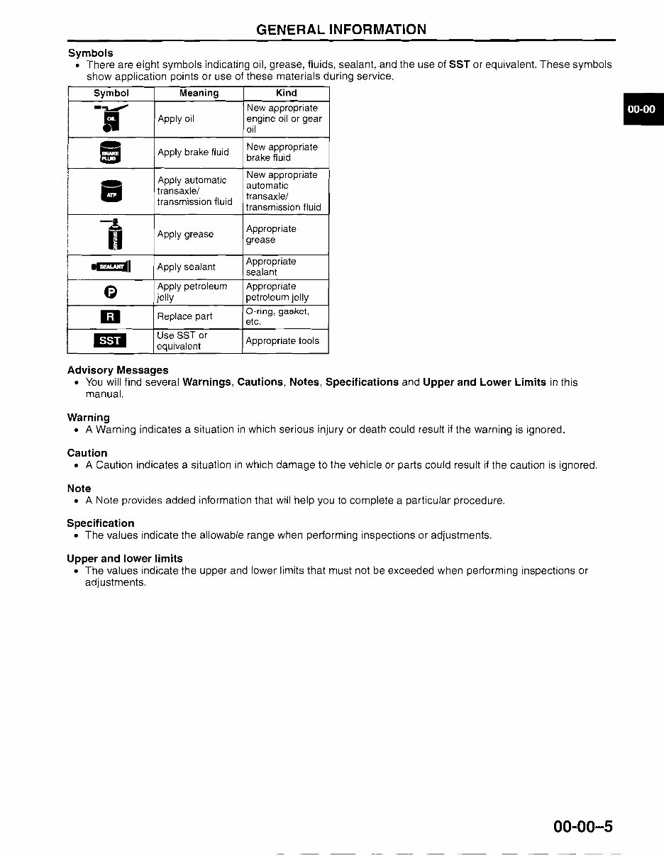
GENERAL INFORMATION Symbols • There are eight symbols indicating oil, grease, fluids, sealant, and the use of SST or equivalent. These symbols show application points or use of these materials during service. .. Symbol Meaning Kind -~ I Apply oil New appropriate engine oil or gear oil • " . Apply brake fluid New appropriate brake fluid I I • Apply automatic transaxle/ transmission fluid New appropriate automatic transaxle/ transmission fluid I I , i -A I Apply grease Appropriate grease I ! ~I Apply sealant Appropriate sealant e Apply petroleum jelly Appropriate petroleum jelly iii Replace part O-ring, gasket, etc. lID Use SST or equivalent Appropriate tools Advisory Messages • You will find several Warnings, Cautions, Notes, Specifications and Upper and Lower Limits in this manual. Warning • A Warning indicates a situation in which serious injury or death could result if the warning is ignored. Caution • A Caution indicates a situation in which damage to the vehicle or parts could result if the caution is ignored. Note • A Note provides added information that will help you to complete a particular procedure. Specification • The values indicate the allowable range when performing inspections or adjustments. Upper and lower limits • The values indicate the upper and lower limits that must not be exceeded when performing inspections or adjustments. 00-00-5
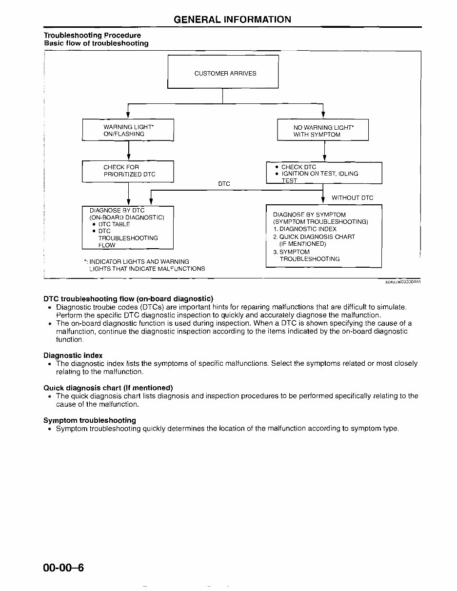
GENERAL INFORMATION Troubleshooting Procedure Basic flow of troubleshooting WARNING L1GHT* ON/FLASHING CHECK FOR PRIORITIZED DTC DIAGNOSE BY DTC • (ON-BOARD DIAGNOSTIC) .. DTCTABLE .. DTC TROUBLESHOOTING FLOW CUSTOMER ARRIVES I DTC *: INDICATOR LIGHTS AND WARNING LIGHTS THAT INDICATE MALFUNCTIONS ! DTC troubleshooting flow (on-board diagnostic) NO WARNING L1GHT* WITH SYMPTOM • ~ .. CHECK DTC .. IGNITION ON TEST, IDLING TEST I ~ WITHOUT DTC DIAGNOSE BY SYMPTOM (SYMPTOM TROUBLESHOOTING) 1. DIAGNOSTIC INDEX 2. QUICK DIAGNOSIS CHART (IF MENTIONED) 3. SYMPTOM TROUBLESHOOTING acxuuw00000444 .. Diagnostic trouble codes (DTCs) are important hints for repairing malfunctions that are difficult to simulate. Periorm the specific DTC diagnostic inspection to quickly and accurately diagnose the malfunction. .. The on-board diagnostic function is used during inspection. When a DTC is shown specifying the cause of a malfunction, continue the diagnostic inspection according to the items indicated by the on-board diagnostic function. Diagnostic index .. The diagnostic index lists the symptoms of specific malfunctions. Select the symptoms related or most closely relating to the malfunction. Quick diagnosis chart (If mentioned) .. The quick diagnosis chart lists diagnosis and inspection procedures to be periormed specifically relating to the cause of the malfunction. Symptom troubleshooting .. Symptom troubleshooting quickly determines the location of the malfunction according to symptom type. 00-00-6
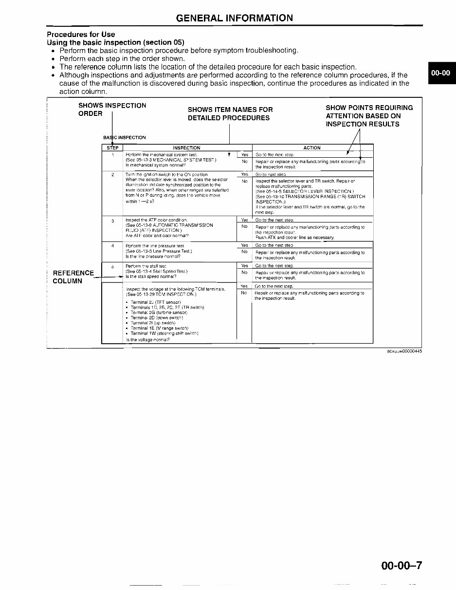
GENERAL INFORMATION Procedures for Use Using the basic inspection (section 05) • Perform the basic inspection procedure before symptom troubleshooting. • Perform each step in the order shown. .. The reference column lists the location of the detailed procedure for each basic inspection. • Although inspections and adjustments are performed according to the reference column procedures, if the cause of the malfunction is discovered during basic inspection, continue the procedures as indicated in the action column. SHOWS INSPECTION S EP INSPECTION Perform the mecnanical system test. Yes (See 05-13-3 MECHANICAL SYSTEM TEST.) No Repair or replace any malfunctioning parts according to Is mechanical system normal? the inspection result. 2 Turn the Ignition switch to the ON position. Yes Go to next step. When the selector lever is moved, does the selector No Inspect the selector lever and TR sWitch. Repair or illumination indicate synchronized position to the replace malfunctioning parts. lever location? Also, when other ranges are selected (See 05-14-5 SELECTOR LEVER INSPECTION.) from N or P during idling. does the vehicle move (See 05-13-10TRANSMISSION RANGE (TR) SWITCH within 1-2 s? INSPECTION.) If the selector iever and TR switch are normal, go to the next step. 3 Inspect the ATF color condition Yes Go to the next steD. (See 05-13-8 AUTOMATIC TRANSMISSION No Repair or replace any malfunctioning parts according to FLUID (ATF) INSPECTION.) The inspection resulT Are ATF color and odor normal? Flush ATX and cooler line as necessary. 4 Perform the line pressure test. Yes Go to the next step. (See 05-13-3 Line Pressure Test.) No Repair or replace any malfunctioning pans according to Is the line pressure normal? the inspection result 5 Perform the stall test. Yes Go to the next steD. REFERENCE (See 05-13-4 Stall Speed Test.) No Repair or replace any malfunctioning parts according to COLUMN Is the stall speed normal? the inspection result. Inspect the voltage at the following TCM terminals. Yes Go to the next step. (See 05-13-29TCM INSPECTION.) No SHOW POINTS REQUIRING SHOWS ITEM NAMES FOR ORDER ATTENTION BASED ON DETAILED PROCEDURES INSPECTION RESULTS BA~ C INSPECTION / ACTION / , Go to the next step. 1 Repair or replace any malfunctioning pans according to the inspection result. · · · · · Terminal 2J (TFT sensor) Terminals 1D, 26, 2C, 2E (TR switch) Terminal 2G (turbine sensor) Terminal 2D (down switch) Terminal 21 (up sWitch) Terminal 1E (M range switch) Terminal 1W (steering shih switch) Is the voltage normal? [ .. acxuuw00000445 00-00-7
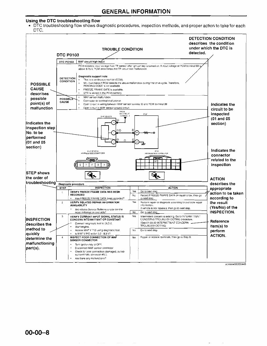
GENERAL INFORMATION Using the DTC troubleshooting flow • DTC troubleshooting flow shows diagnostic procedures, inspection methods, and proper action to take for each DTC. I I I POSSIBLE CAUSE describes possible point(s) of malfunction I Iindicates the inspection step No. to be performed (01 and 05 section) STEP shows the order of troubleshooting ---..:.. INSPECTION describe sthe method t 0 / quickly Idetermin ethe 'malfunct ioning part(s). [ I TROUBLE CONDITION DTC P0103 DTC P0103 MAF circuit high input DETECTION CONDITION Diagnostic support note This is a continuous monitor (GeM). MIL illuminates if PCM detects the above malfunction during first drive cycle. Therefore, PENDING CODE is nor available FREEZE FRAME DATE is available. DTC is stored in the PCM memory. PCM monitors input voltage from TP sensor after ignition key is turned on. If Input voltage at PCM terminal 68 ! above 8.25 V. PCM determines thai TP Circuit nas malfunccion POSSIBL CAUSE MAF sensor malfunction Connector or terminal malfunction Open circuit in wiring between MAF sensor terminal 0 and PCM terminal 36 o en circuit in MAF sensor round circuit lP PCM HARNESS SIDE COM~ECTOR FROM MAIN RELAY PCM TERMINAL D MAF SENSOR HARNESS SIDE CONNECTOR Diagnostic procedure describes the STEP INSPECTION ACTION appropriate 1 VERIFY FREEZE FRAME DATA HAS BEEN RECORDED Yes No Go to next step. Record FREEZE FRAME DATA on repair order, then go ~ / action to be taken Has FREEZE FRAME DATA been recorded? to next step, according to 2 VERIFY RELATED REPAIR INFORMATION Yes Perform repair or diagnosis according to available repair the result AVAILABILITY Are related Service Bullelins and/or on-line information. If vehicle is not repaired. then go to next step. (Yes/No) of the repair information available? No Go to next steD. INSPECTION. 3 VERIFY CURRENT INPUT SIGNAL STATUS IS Yes Intermittent concern is existing. Go to INTERMITTENT CONCERN INTERMITIENT OR CONSTANT / Connect diagnostic tool to DLC-2. Start engine. Access MAF V PID using diagnostic tool. No CONCERNS TROUBLESHOOTING procedure. (See 01-03-33INTERMITIENT CONCERN _ TROUBLESHOOTING) Go to next step. Reference item(s) to perform Is MAF V PID within 02 - 8.3 V? 4 INSPECT POOR CONNECTION OF MAF Yes Repair or replace terminals, then go to Step 8. ACTION. SENSOR CONNECTOR Turn ignition key to OFF. Disconnect MAF sensor connector Check for poor connection (damaged, pulled- out terminals, corrosion etc.). Are there any malfunctions? DETECTION CONDITION describes the condition under which the DTC is detected. Indicates the circuit to be inspected (01 and 05 section) Indicates the connector related to the inspection ACTION acxuuw00000446 00-00-8
The Mazda 3 2004-2008 Service Repair Manual provides comprehensive coverage for models from 2004 to 2008. It encompasses all repairs from A-Z, offering vehicle-specific information essential for both professional mechanics and DIY enthusiasts.
This manual includes complete step-by-step instructions, diagrams, illustrations, wiring schematics, and specifications to facilitate easy vehicle repair. It eliminates the need to search through multiple books, allowing you to print only the necessary pages and diagrams. The printable pages enable you to carry the required information to your vehicle or workshop, and you can also enlarge and print images as needed.
These factory repair manuals are compatible with Windows Vista 32 and 64, XP, ME, 98, NT, 2000, and Mac, ensuring accessibility for a wide range of users. By obtaining this manual, you can independently maintain, service, diagnose, and repair your vehicle, resulting in significant cost savings.
It is an invaluable resource for all car and truck repair needs, offering instant access upon payment via PayPal or credit card.