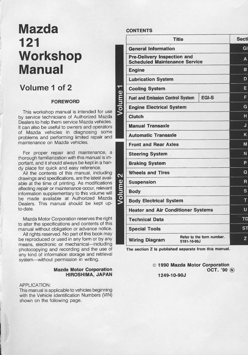
Mazda 121 Workshop Manual Vof ume 1 of 2 FOREWORD This workshop manualis intended for use bv service techniciansof AuthorizedMazda D-ealers to help them serviceMazdavehicles. It can also be uselulto ownersand operators of Mazda vehicles in diagnosing some problems and performing limited repairand maintenance on Mazda vehicles. For proper repair and maintenance, a thorough lamiliarization with thismanual is im- portant, and it shouldalwaysbe keptin a han- dy placefor quick and easy reterence. All the contents of this manual,including drawings and specifications, arethe latest avail- able at the time of printing. As modifications affecting repairor maintenance occur,relevant information supplementary to thisvolume will be made available at Authorized Mazda Dealers. This manual should be kept up- to-date. Mazda Motor Corporation reserves the right to alterthe specifications and contents of this manual without obligation or advance notice. All rightsreserved. No part of this book may be reproduced or used in any form or by any means,electronic or mechanical-including photocopyingand recording and the use of any kind oJ information storage and retrieval system-without permission in writing. Mazda Motor Corporation HIROSHIMA. JAPAN APPLICATION: This manual is applicable to vehicles beginning with the Vehicle ldentification Numbers (VlN) shown on the following page. o 1990 Mazda MotorCorporation ocT. '90 @) 1249-10-90J CONTENTS Tirle Secti Generallnformation Pre-Delivery Inspectionand Scheduled Maintenance Service Engine Lubrication System Cooling System Fuel and Emission C,onttol System I EGI-S Engine ElectricalSystem Clutch ManualTransaxle Automatic Transaxle Front and Rear Axles Steering System Braking Syslem Wheels and Tires Suspension Body Body Electrical System Heater and AarConditioner Systems Technical Data Special Tools wiringDiasram Sili:.|Tj|:'"''""'0"'' The section Z is publishedseparate lrom this manual.
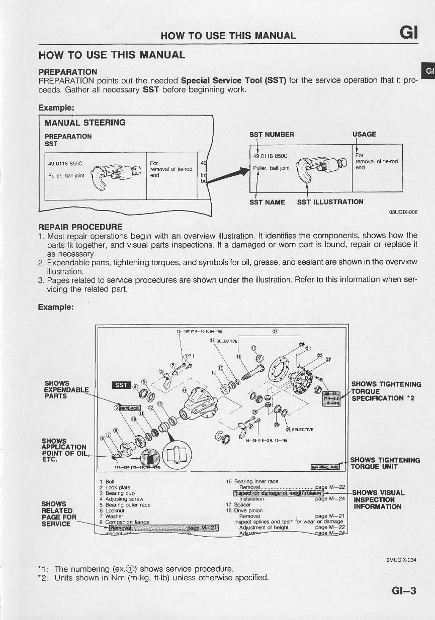
HOWTO USE THISMANUAL GI HOW TO USE THISMANUAL F[rtFf#rtifiiroints out the needed speciat service Tool (ssT) for the service operation mat it pro- E ceeds. Gather all necessary SST before beginning work. Example: SST NUMBER SST NAME SST ILLUSTRATION 03uGtx-@6 REPAIB PROCEDURE 1. Most repair operations beginwithan overview illustration. lt identifies the components, shows howthe parts fit together, and visual parts lnspections. lf a damaged or wornpart is found, repair or replace it as necessary. 2. Expendable parts, tightening torques, and symbols foroil, grease, and sealant are shown intheoverview illustration. 3. Pages related to service procedures areshown under the illustration. Befer to thisinformation when ser- vicing the related part. Example: SHOWS TIGHTENING TOROUE UNIT sHows RELATED PAGE FOR SERVICE "1: The numbering (ex.@) shows service procedure. Units shown in Nm (m-kg, ftJb)unless otherwise specified. 9MUGIX.O34 Gt-3 MANUAL STEERING PREPARATION ssT 49 0118 850C Pullef, ball joinl 17 Spacer 18 Drive pinion Bemoval page M-2'l rpecl splines and leelh fot weat or damage
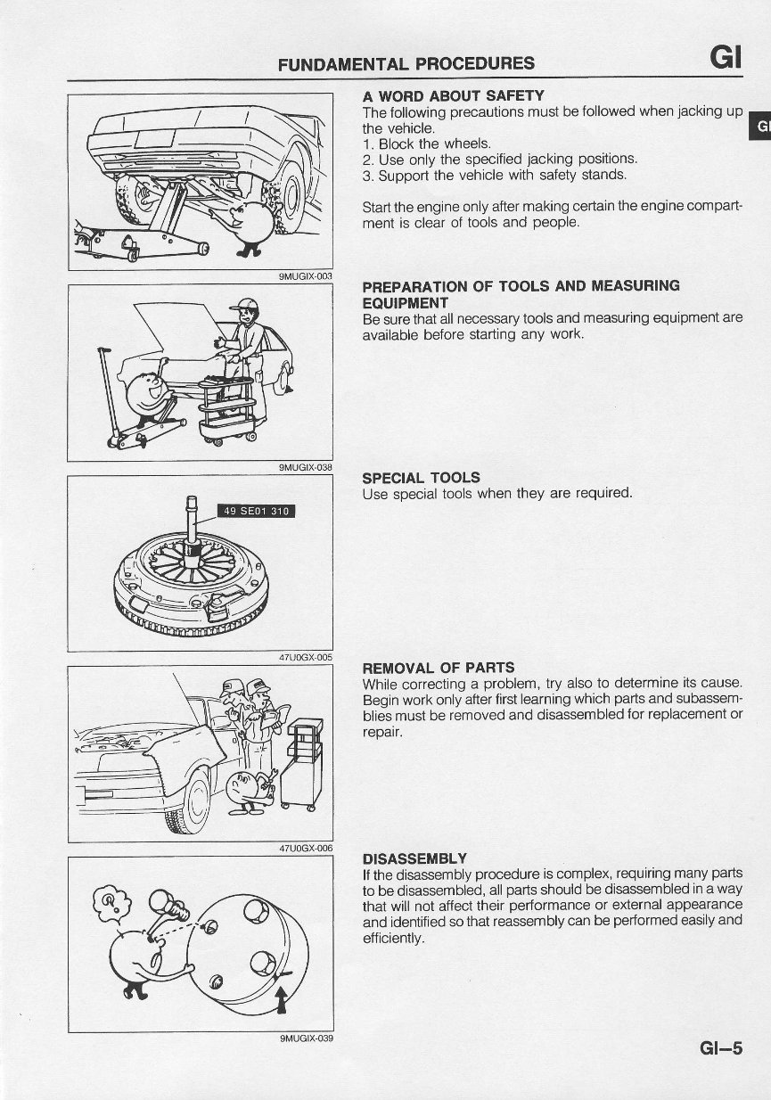
FUNDAMENTAL PROCEDURES GI 9MUGtX-003 9[,{UGtX-038 47UOGX-005 47U0GX-006 SMUGIX,O39 A WORD ABOUT SAFETY The following precautions must befollowed when jacking up the vehicle. 1 . Block the wheels. 2. Useonly the specified jacking positions. 3. Support the vehicle with safety stands. Start theengine only after making certain theengine compart- ment is clear of tools and people. PREPARATION OF TOOLS ANDMEASURING EOUTPMENT Besure that allnecessary tools and measuring equipment are available before starting any work. SPECIAL TOOLS Use special tools when they are required. REMOVAL OF PARTS While correcting a problem, try also to determine its cause. Begin workonlyafter firstlearning which parts and subassem- b es mustbe removed and disassembled for replacement or repair. DISASSEMBLY lf the disassembly procedure is complex, requiring many parts to be disassembled, all parts should be disassembled in a way that will not affect their performance or external appearance and identified so thatreassembly can be performed easily and efficiently. Gr-5
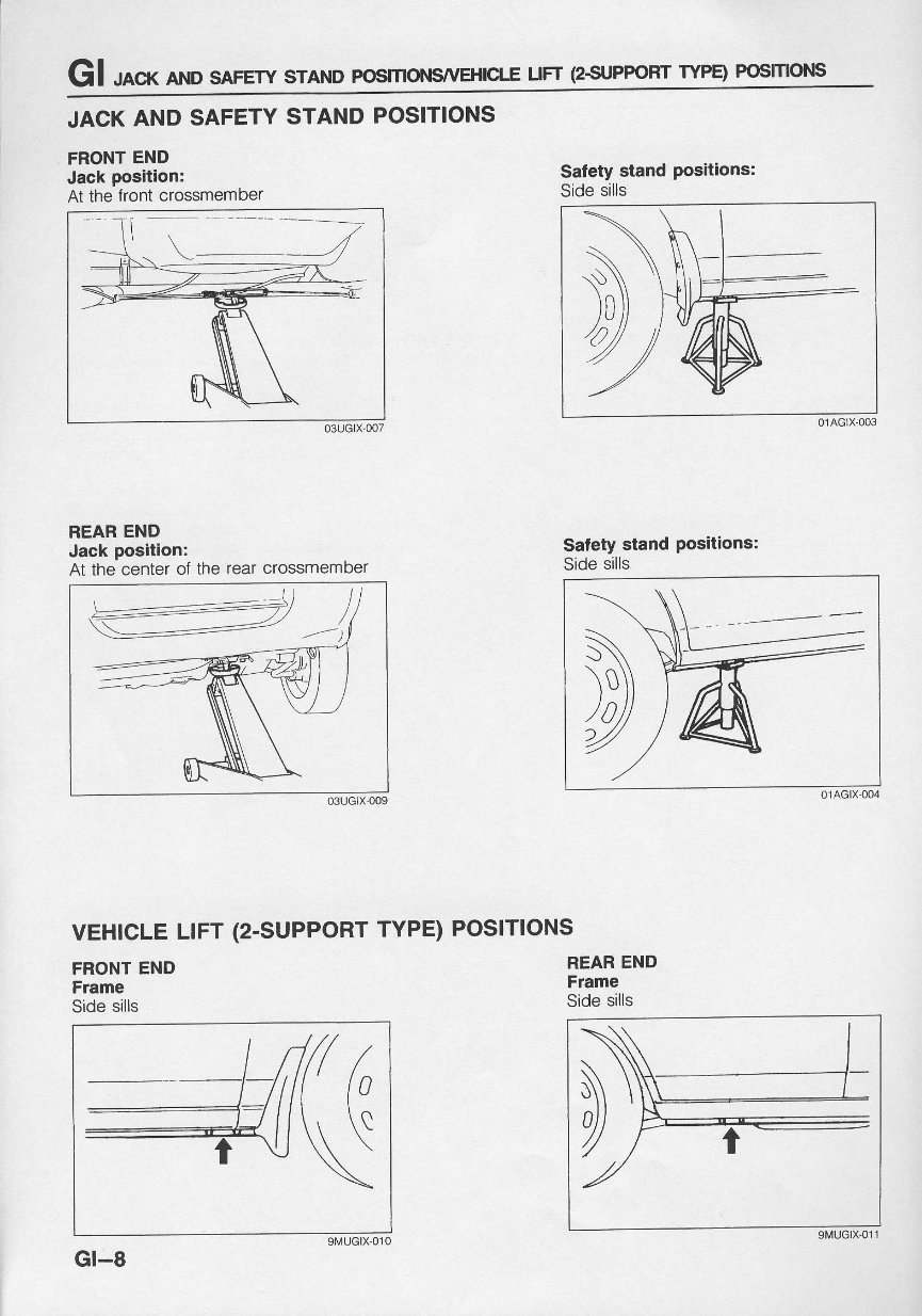
Gl ,oo AND sAFEw srANDFosmoNsyvEHplE UFT (25UPP6RT TYPE) FosmoNs JACKAND SAFETY STANDPOSITIONS FRONT END Jack positioni At the frontcrossmember Satetystand positions: Side sills REAR END Jack position: At the center of the rear crossmember Safetystand positions: Side sills 03uGlx'oog vEHlcLE LIFT (2-SUPPORT TYPE)POSITIONS FRONT END Frame Side sills 9ltlUGlX-010 Gt-8 REAREND Frame Side sills
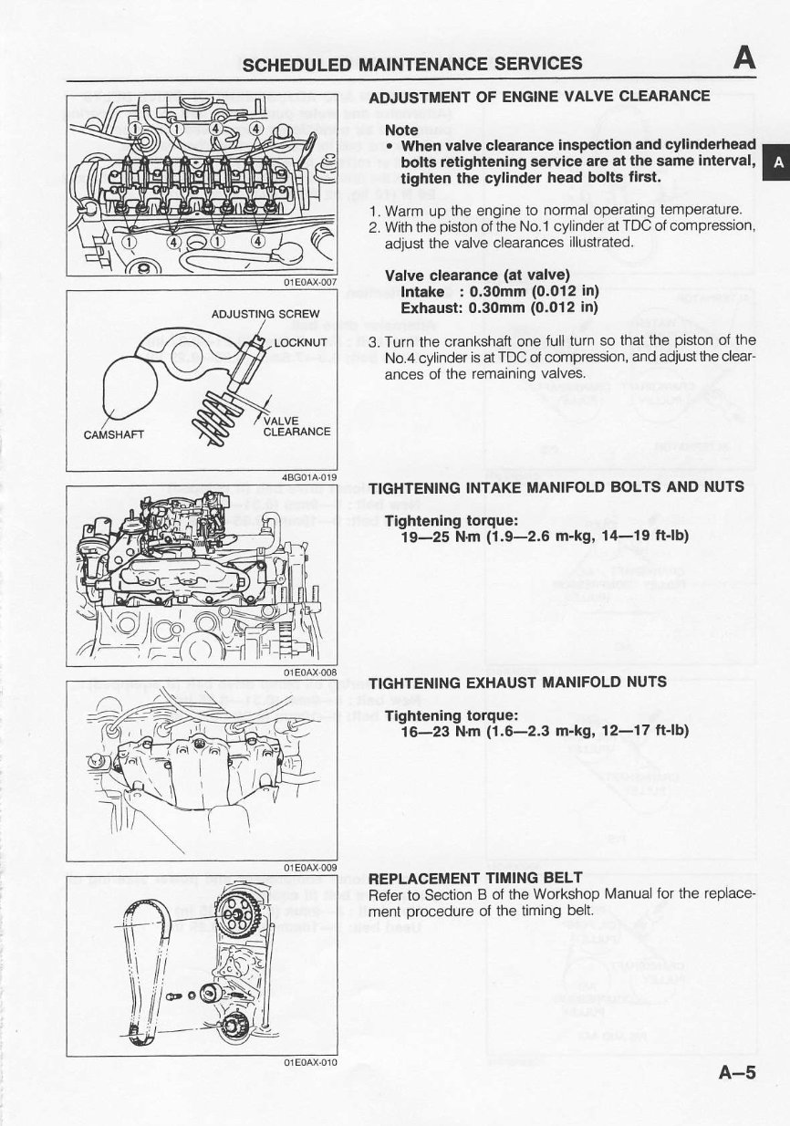
SCHEDULED MAINTENANCE SERVICES ADJUSTING SCFEW LOCKNUT ADJUSTIIENT OF ENGINE VALVE CLEARANCE Note . When valve clearance inspection and cylindefiead r bolts retightening service are ai the same interval, E tlEhtenthe cylinderhead bolts tlrst. I 1. Warm up the engine to normal operating temperature. 2. With the piston oftheNo.1 cylinderat TDC ofcompression, adjust the valve clearances illustrated. valve clearance (at valve) lntake : 0.30mm (0.012in) Exhaust: 0.30mm (0.012in) 3. Turn the crankshaft onefull turn so that the piston of the No.4 cylinder isatTDC ol compression, andadjusl the clear- ances of the remaining valves. TIGHTENING INTAKE MANIFOLD BOLTS AND NUTS Tightening torque: 19-25 N.m (1,9-2.6 m-kg, 14-19 ttlb) TIGHTENING EXHAUST MANIFOLD NUTS Tightening lorque: 16-23 Nm (1.6-2.3 m-kg, 12-17 ftlb) REPLACEMENT TIMING BELT Refer to Section I ot theWorkshop Manual for the replace- ment procedure of the timing belt. A-5
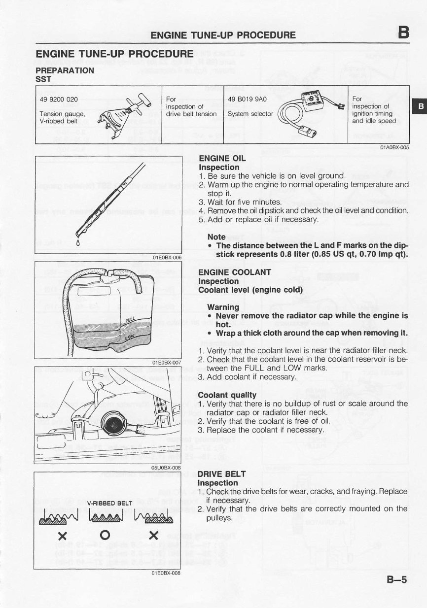
ENGINE TUNE-UP PROCEDURE ENGINE TUNE.UP PROCEDURE PBEPARATION ssr 49 9200 020 Tension gauge, 49 8019 9A0 ignilion liming ENGINE OIL Inspection 1. Be sure the vehicle is on level ground. 2. Warm up theengineto normaloperating temperature and stop rI. 3. Wait for fiveminutes. 4. Remove the oil dipstick and check the oilleveland condition. 5. Add or replace oil if necessary. Note . Thedislance belween the Land F marks on lhe dip. stick repressnts 0.8 liter (0.85 US qt, 0.70lmp qt). ENGINE COOLANT Inspectign Coolantlevel (englne cold) Warning . Never remove the radiator cap whlle the engineis hot. . Wlapa thlckclotharound the capwhenremoving il. 1. Verily that thecoolant level is near the radiator filler neck. 2. Check that thecoolant level in thecoolant reservoir is be' tween the FULL and LOW marks. 3. Add coolanl il necessary. Coolanlquality 1. Verify that there is no buildup oi rust or scale around the radiator cap or radiator filler neck. 2. Verify thatthe coolant is freeof oil. 3. Fleplace the coolanl ii necessary. ORIVE BELT Inspection 1. Checkthe drive belts for wear, cracks, and fraying. Replace if necessary. 2. Verity thatthe drivebelts are correctly mounted on the puleys. V.RIBEED 6ELT MtwJtM o x x B-5
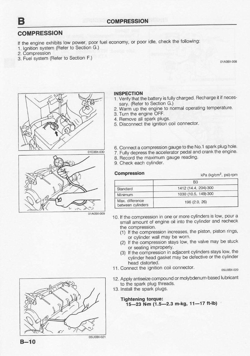
COMPRESSION COMPRESSION ll rheenoine exnibits low power. poorluel economy or poorldle check the lollowing: 1. lgnrtro; system (Beler to Sectron G.) 2. Compressron 3. Fuel svstem (Fefer to Section F.) INSPECTION 1 . Verifv that thebattery istully charged Recharge it if neces- sarv. (Refer to Section G.) 2. Warm up the engine to normal operating lemperature' 3. Turn the engine OFF. 4. Bemove all spark plugs. 5. Disconnect the ignition coilconnector' 6. Connect acompression gaugetothe No l spark plug hole 7. Fr.rlly depress lhe acceleiator pedal andcrank the engine' 8. Record the maxrmum gauge reaolng 9. Check each cylinder. Compression kPa (kg/cm', psilrpm B3 Siandard 1412 1t4.4, 2O4!3OO 1030 00.5, 149)-300 't96 (2.O, 26) 10.lf thecompression in one or more cyllnders s rcw'pour a small amount of engine oil into the cylinder and recheck the compressrcn. (1) lt thecompression increases, the piston, piston rings' or cvlinder wallmavbe worn (2) lf the compression stays low, the valve maybe stuck or seating imProperly. {3) lt thecomoression in adjacent cylinders stays low, the ' ' cvlinder head gaskel may be delective orthe cylinder head distorted. 11 . Connect the ignition coil connector. 12. Apply antiseize compound or molybdenum-based lubricant to the spark Plug threads. 13. Insiallthe spark Plugs. Tidhlenino toroue: is-zsi{.m (i.5-2.3 m'ks' 11-17 finb) B-10
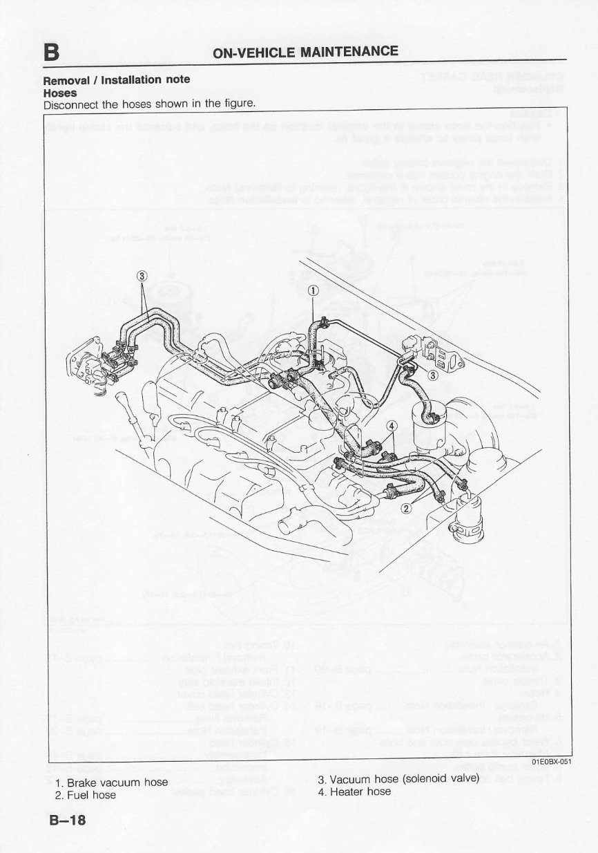
ON.VEHICLE MAINTENANCE Removal / Installation ngte Hoses Disconnect the hoses shown in the figure. '1. Brake vacuum hose 2. Fuel hose B-18 3. Vacuum hose (solenoid valve) 4. Heater hose
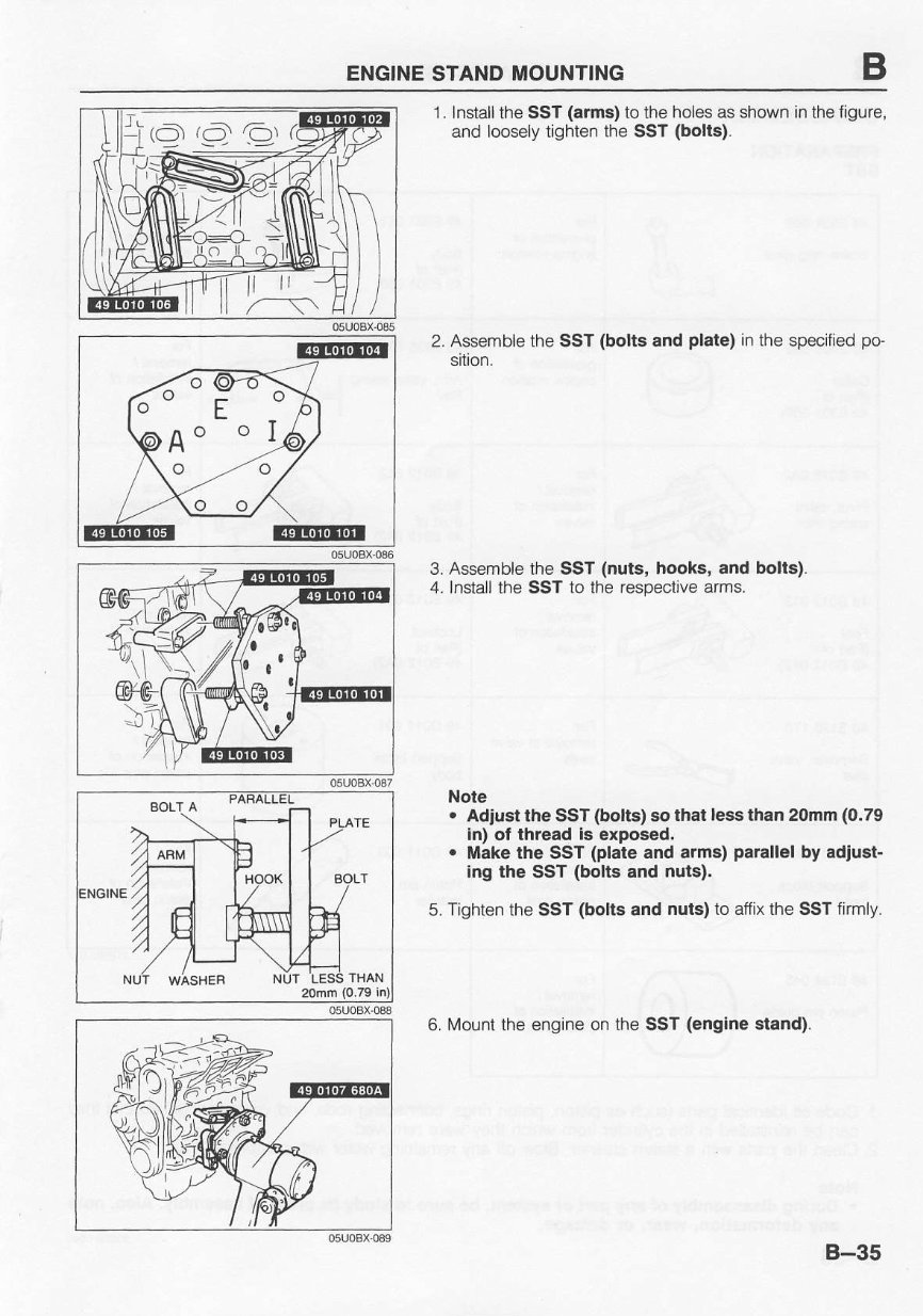
ENGINE STANDMOUNTING - F AO O I 20mm(0.79 i 1. lnstall theSST(arms) to theholes as shown in the figure, and loosely tighten the SST (bolts). 2. Assemble the SST (bottsand plale)in the specilied po- sition. 3. Assemble the SST (nuls, hooks, and bolts) 4. Install the SST to the respective arms. Note . Adiust the SST Oolts) so that lea¤ than 20mm(0.79 in) ol thread is exposed. . Make the SsT (plateand arms) parallel by adiust- Ing the SST (bolts and nuis). 5. Tighten theSST (boltsand nuts)to atfix the SST firmly. 6. Mount the engine on the SST (englne stand). ji,--\ ,.=r l-' - \\J, ie ui B-35
This Mazda 121 1990-1998 Full Service & Repair Manual is the essential guide for any Mazda 121 owner. Whether you are a DIY enthusiast or a professional mechanic, this comprehensive manual will provide you with all the necessary information to service and repair your vehicle.
With detailed step-by-step instructions, diagrams, and illustrations, you can easily tackle any repair or maintenance task on your Mazda 121. From routine oil changes to complex engine repairs, this manual covers it all.
The Mazda 121 1990-1998 Full Service & Repair Manual includes:
Comprehensive coverage of all models from 1990 to 1998
Detailed instructions for engine, transmission, and electrical system repairs
Diagnostic procedures and troubleshooting guides for common issues
Maintenance schedules and procedures
Wiring diagrams and specifications
Exploded views and parts lists
Tips and advice from professional mechanics
Whether you need to perform a simple repair or undertake a major overhaul, this service and repair manual is your go-to resource. Don't let mechanical issues hold you back – equip yourself with the knowledge and confidence to keep your Mazda 121 running smoothly.