

2013-2016 Lincoln MKS Service & Repair Manual
What's Included?
Fast Download Speeds
Offline Viewing
Access Contents & Bookmarks
Full Search Facility
Print one or all pages of your manual

2013 MKS
Workshop Manual
Quick Links
Introduction
Master DTC Chart
Specifications
Metrics
Torque Wrench Adapter Formulas
Acronyms
Alphabetical Index
Table of Contents
1: General Information
00: Service Information
2: Chassis
04: Suspension
05: Driveline
06: Brake System
11: Steering System
3: Powertrain
03: Engine
07: Automatic Transmission
08: Manual Transmission, Clutch and Transfer Case
09: Exhaust System
10: Fuel System
4: Electrical
12: Climate Control System

13: Instrumentation and Warning Systems
14: Battery and Charging System
15: Audio Systems
17: Lighting
18: Electrical Distribution
19: Electronic Feature Group
5: Body and Paint
01: Body
02: Frame and Mounting
SECTION 100-00: Service Information 2013 MKS Workshop Manual
DESCRIPTION AND OPERATION Procedure revision date: 04/27/2012
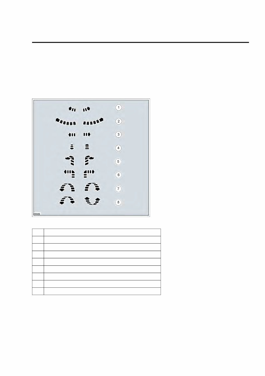
Symbols Glossary
Symbols are used inside the graphics and in the text area to enhance the information.
Movement Symbols
Movement symbols provide detailed information to a required component movement. These component
movements can be rotational or 1-3 dimensional movements.
Item Description
1 Minor component movement clockwise/counterclockwise
2 Major component movement clockwise/counterclockwise
3 Component movement to the left/right/up/down
4 Component movement towards/away
5 3 dimensional component movement
6 2 dimensional component movement
7 3 dimensional component rotation
8 3 dimensional component cycling
Turn Symbols
Turn symbols are used to provide further information on the direction or angle of component turns.
2013 MKS Workshop Manual
Symbols Glossary 1
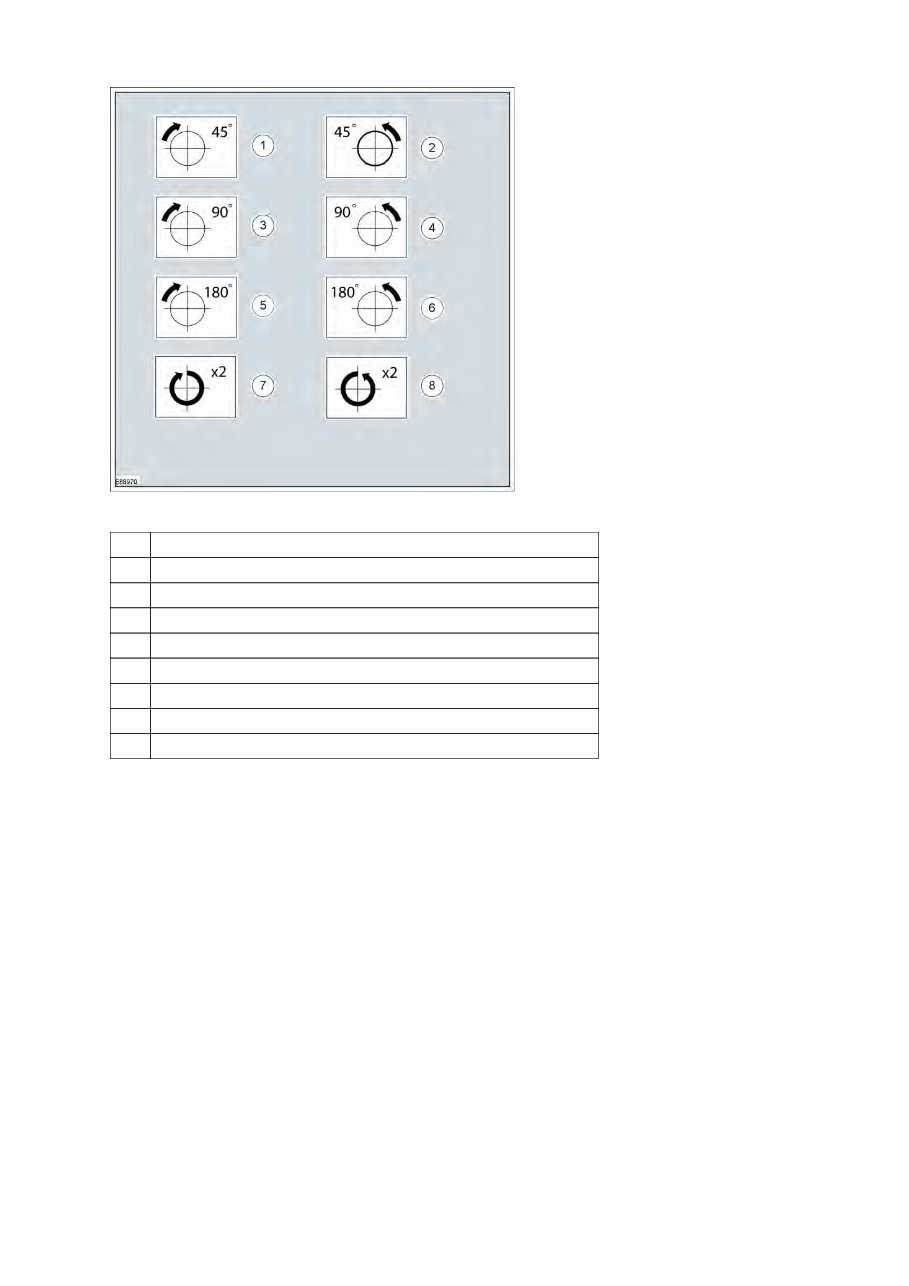
Item Description
1 Turn the component clockwise through 45°
2 Turn the component counterclockwise through 45°
3 Turn the component clockwise through 90°
4 Turn the component counterclockwise through 90°
5 Turn the component clockwise through 180°
6 Turn the component counterclockwise through 180°
7 Turn the component clockwise through 2 complete turns
8 Turn the component counterclockwise through 2 complete turns
Steering Wheel Symbols
Steering wheel symbols are used to provide further information to a required steering wheel position or
steering column lock status.
2013 MKS Workshop Manual
Symbols Glossary 2
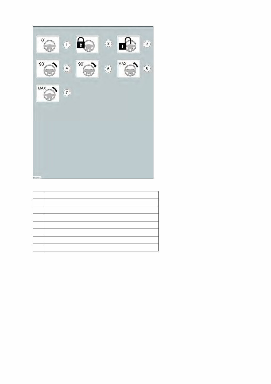
Item Description
1 Steering wheel in straight ahead position
2 Steering column lockd
3 Steering column lock unlocked
4 Turn the steering wheel to the 90° left position
5 Turn the steering wheel to the 90° right position
6 Turn the steering wheel to the left-hand end position
7 Turn the steering wheel to the right-hand end position
Body Types
Body type symbols are used to identify different body configurations.
2013 MKS Workshop Manual
Symbols Glossary 3
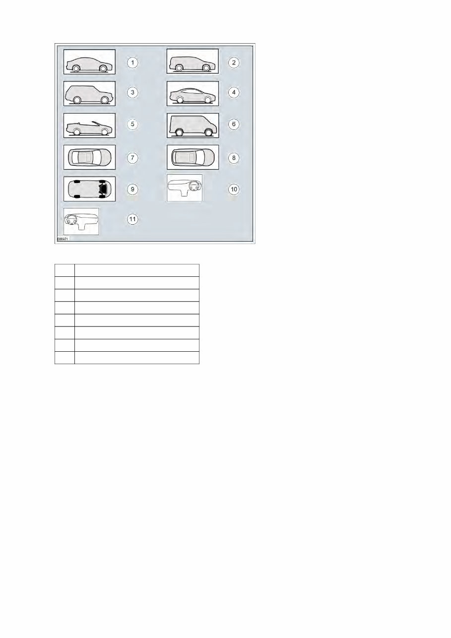
Item Description
1 3, 4, 5-door body style
2 Wagon body style
3 Sport utility vehicle body style
4 Coupe body style
5 Convertible body style
6 Van body style
7 3, 4, 5-door body style - Top View
2013 MKS Workshop Manual
Symbols Glossary 4

SECTION 100-00: Service Information 2013 MKS Workshop Manual
DESCRIPTION AND OPERATION Procedure revision date: 02/14/2012
Using This Manual
Introduction
This manual describes and directs repair procedures for this vehicle model year. It includes diagnostics for all
vehicle systems except driveability and emission control. Refer to the separate Powertrain Control/Emissions
Diagnosis (PC/ED) manual for driveability and emission control diagnostics.
Information is organized into groups, with sections that have subsections dividing them.
Warnings, Notices, and Notes in This Manual
Warnings provide information to avoid personal injury and to make sure service actions on critical safety
systems are performed correctly.
Notices provide information to avoid damage to the vehicle or a component.
Notes provide information critical for a complete and effective repair.
Warnings that apply to an entire system or workshop manual section are located in section 100-00 Description
and Operation Safety Warnings .
Warnings, Notices, or Notes that apply to an entire procedure will be placed at the beginning of the procedure.
Warnings, Notices, or Notes that apply to a single step are placed at the beginning of the step. Those that
apply to a group of steps will be placed at the first step requiring it.
Vehicle and Engine Orientation Identifiers
LH and RH vehicle designations are oriented from the driver's seat position looking forward. LH and RH
engine designations are oriented from the flywheel position looking towards the crankshaft pulley.
How to Use Diagnostic Information
DTC and Symptom Charts
Module DTC Charts are used to begin and direct the diagnosis of a DTC. Symptom Charts contain concern
symptoms and direct solutions either in the chart or in a linked Diagnostic Routine. Both DTC and Symptom
Charts may provide the solution within the chart, or provide a link to the appropriate Diagnostic Routine.
In some sections, the Symptom Chart is preceded by a Preliminary Inspection which must be followed prior to
using the Symptom Chart
Using Module DTC Charts
This Workshop Manual contains diagnostics for DTCs set by vehicle modules. Driveability and emission
DTCs are covered in the separate Powertrain Control/Emissions Diagnosis (PC/ED) manual. If a PCM-set
DTC is not listed in the Workshop Manual, it is serviced in the Powertrain Control/Emissions Diagnosis
(PC/ED) manual.
DTC diagnostics are found in both on-line and printed publications and are used as follows:
2013 MKS Workshop Manual
Using This Manual 5
On-line publications: Using the left side menu, click on the Master DTC Chart link to view the
vehicle module DTC charts. Each module has a chart with links or in-chart solutions for all DTCs
diagnosed in the Workshop Manual.
•
Printed publications: Use the DTC index in the rear of the book. •
Diagnostic Methods
Diagnostic Methods provides information to support diagnosing Ford vehicles. Diagnostic strategies,
diagnostic tool support information, and advanced circuit testing methods are included. REFER to Diagnostic
Methods .
Diagnostic Routines
Diagnostic Routines provide information to determine the root cause of concerns addressed in either a DTC
Chart or Symptom Chart. Each Diagnostic Routine contains:
Diagnostic Overview
Wiring Diagram References (as applicable) ♦
Normal Operation and Fault Conditions ♦
Visual Inspection and Diagnostic Pre-checks ♦
•
Tool Table (as applicable) •
Material Table (as applicable) •
Pinpoint Test Steps •
Component Tests
Component Tests are used to separately analyze a single common component in a system. The test will
determine if the part is functioning correctly.
Mechanical Procedures Such As Removal and Installation
Reuse Of Fasteners, Seals, Or Gaskets
The following is a list of assumptions made in the reuse of fasteners, seals, or gaskets.
Seals and gaskets must be replaced unless otherwise specified. •
Standard fasteners are reused unless otherwise specified. •
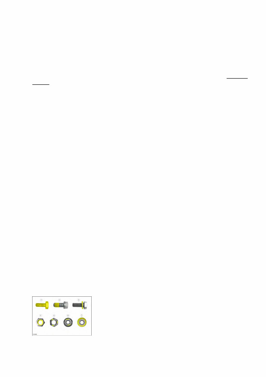
Fasteners with self-locking features must be replaced unless otherwise noted. Reminder text may or
may not be included with the procedure step. Examples of fastener coatings or fasteners with
mechanical locking (with the locking features highlighted yellow) are shown in illustration 1.
•
Torque to yield bolts (bolts with more than one stage of tightening torque and a final torque angle
specification) must be discarded and new torque to yield bolts installed unless otherwise stated within
the procedure.
•
Illustration 1 - self-locking coatings or locking feature are highlighted yellow
Graphics
2013 MKS Workshop Manual
Illustration 1 - self-locking coatings or locking feature are highlighted yellow 6
Illustrations in this manual may be used to replace written step instructions. Color-coding (see color scheme in
this document) is used to communicate the required step action or actions. Service action icons (see Symbols
Glossary ) are used to add additional information regarding the required action.
The color scheme in a step graphic (an illustration used in removal or installation steps) indicates
servicing information as follows:
Fasteners (including panel retainers) or electrical connectors - Magenta (Purple) ♦
Target component that is to be removed - Blue ♦
Components that must be removed prior to the target component shown in blue - Brown or
Green
♦
Components placed aside for access, but not removed; highlighted areas such as inspection
areas, adjustments or measurements - Yellow
♦
Essential Special Service Tools (ESSTs) and other tools - Pale Blue ♦
Chemical or Sealer apply areas - Alternating blue and white dashes (see illustration 4) ♦
Sectioned or cut-away areas - Red ♦
Remaining components - Grey ♦
•
Callouts in graphics indicate removal (or tightening) order, or identify individual instructions in substeps of
the same number (such as different torque values).
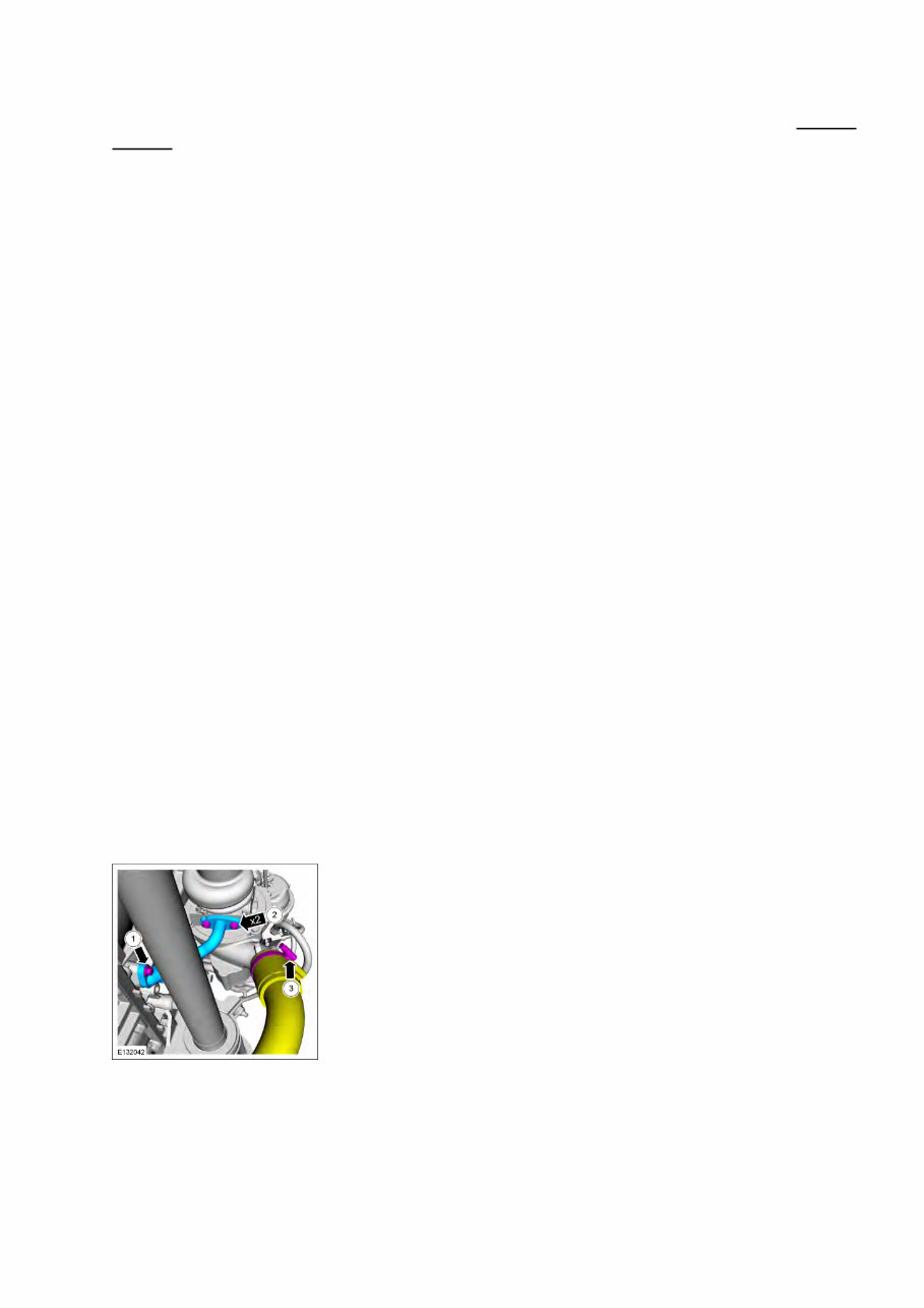
Arrows containing x numbers (Illustration 2) indicate the number of identical fasteners or connectors to be
removed or installed in the graphic.
In Illustration 2, two identical fasteners are indicated by the x2 arrow, with another arrow illustrating a third
fastener of a different type. Because the different fasteners require different torques, callouts are used to
identify those two torque values in the associated step text. The hose clamp is another fastener to be removed.
The yellow coloring of the hose indicates it is to be moved aside (not removed).
The following written steps would be necessary if the illustration did not have color coding:
Remove the engine oil pipe fastener at the engine connection. 1.
Remove the two engine oil pipe fasteners from the turbocharger and remove the pipe. 2.
Remove the air inlet hose from the turbocharger and position aside. 3.
Illustration 2
Hidden fasteners, such as panel retainers, are identified in the illustration by a magenta disc. An inset detail
view illustrating the fastener type may be included (Illustration 3).
2013 MKS Workshop Manual
Illustration 2 7
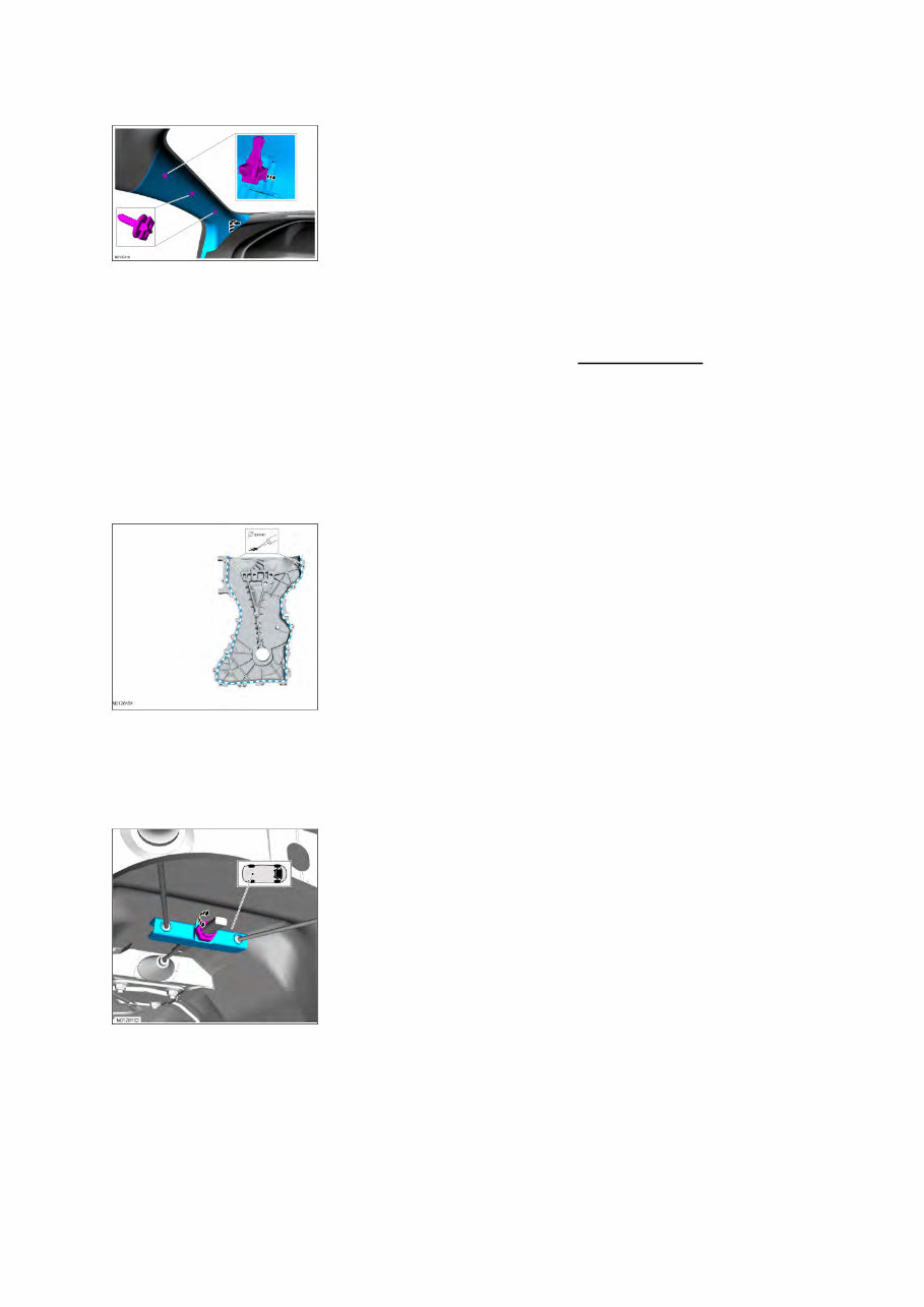
Illustration 3 - Note motion arrow at panel bottom; it indicates to lift panel up, then move inward to remove
Symbols
Symbols may be used inside graphics or in the text area to communicate service actions. The following
examples demonstrate the use of some of these symbols. REFER to Symbols Glossary for a complete symbols
list with explanations.
In the Illustration 4 example, service action symbols are shown as used to direct the application of sealer,
lubricant, weight, tape or cleaning detergent to a component. In this example a bead diameter of "xx"
millimeters is prescribed. The blue and white dashes indicate where the material is applied.
Illustration 4
Illustration 5 is an example of location symbols used to show the location of a component tem within the
vehicle.
Illustration 5
Illustration 6 shows how gearshift lever or selector lever position symbols may be used to indicate the
gearshift lever or selector lever position required. The required Essential Special Service Tool to align the
shift mechanism is shown in pale blue and identified by ESST number.
Illustration 6
2013 MKS Workshop Manual
Illustration 3 - Note motion arrow at panel bottom; it indicates to lift panel up, then move inward to remove 8
You're Reading a Preview
What's Included?
Fast Download Speeds
Offline Viewing
Access Contents & Bookmarks
Full Search Facility
Print one or all pages of your manual
$41.99
Viewed 11 Times Today


Secure transaction
What's Included?
Fast Download Speeds
Offline Viewing
Access Contents & Bookmarks
Full Search Facility
Print one or all pages of your manual
$41.99
Thank you for considering this comprehensive 2013-2016 Lincoln MKS Service & Repair Manual. This manual is an invaluable resource covering every Service & Repair Procedure for your Lincoln MKS. It is designed to assist both professional mechanics and DIY enthusiasts in performing their own repairs, helping you save money with easy-to-follow, step-by-step instructions and detailed images for each procedure.
Once downloaded, this manual is yours to keep forever. You have the flexibility to print specific pages, chapters, or the entire manual, and conveniently access it on your tablet or smartphone.
Models Covered:
- All Models, Engines, Trim, & Transmission Types for the 2013-2016 Lincoln MKS are Covered
Contents:
- This high-quality Service & Repair Manual includes every procedure from A to Z.
- Every repair and service procedure is comprehensively detailed.
Computer Requirements:
- This downloadable Manual is compatible with all PC & MAC Computers, tablets, and mobile phones.
- The only software required is Adobe Reader, typically pre-installed. If not, it can be downloaded for free.
Instant Delivery:
- Upon payment confirmation via Visa, MasterCard, or PayPal, the manual will be instantly emailed to your provided address.
Customer Satisfaction Guaranteed.


