TRANSMISSION A760H Automatic Transaxle - IS250 AUTOMATIC TRANSMISSION SYSTEM PRECAUTION SYSTEM NAME CHART HINT: RESET MEMORY can not be completed by only disconnecting the battery cable. 1. REMOVAL AND INSTALLATION PROCEDURE PRECAUTIONS a. The automatic transmission is composed of highly precision-finished parts which need careful inspection before reassembly. Even a small nick could cause fluid leakage or affect the performance. The instructions here are organized so that you work on only one component group at a time. This will help avoid confusion caused by similar-looking parts of different sub-assemblies being on your workbench at the same time. The component groups are inspected and repaired from the converter housing side. Complete the inspection, repair and reassembly before proceeding to the next component group as much as possible. If a defect is found in a certain component group during reassembly, inspect and repair this group immediately. If a component group cannot be assembled because some parts are being ordered, be sure to keep all parts of the group in a separate container while proceeding with disassembly, inspection, repair and reassembly of other component groups. Recommended: Toyota Genuine ATF WS b. All disassembled parts should be washed clean and any fluid passages and holes should be blown through with compressed air. c. Dry all parts with compressed air. Never use a shop rag or a piece of cloth to dry them. d. When using compressed air, always aim away from yourself to prevent accidentally spraying ATF or kerosene in your face. e. Only recommended automatic transmission fluid or kerosene should be used for cleaning. f. After cleaning, the parts should be arranged in the correct order for efficient inspection, repair, and reassembly. NOTE: When the negative (-) battery cable is disconnected, initialize the following systems after the cable is reconnected. System Name See procedure Power Window Control System INITIALIZATION NOTE: Perform the RESET MEMORY (AT initialization) when replacing the automatic transmission assembly, engine assembly or ECM (See INITIALIZATION ).
g. When disassembling a valve body, be sure to match each valve together with the corresponding spring. h. New discs for the brakes and clutches that are to be used for replacement must be soaked in ATF for at least 15 minutes before reassembly. i. All oil seal rings, clutch discs, clutch plates, rotating parts, and sliding surfaces should be coated with ATF prior to reassembly. j. All gaskets and rubber O-rings should be replaced with new ones. k. Do not apply adhesive cements to gaskets and similar parts. l. Make sure that the ends of a snap ring are not aligned with one of the cutouts and are installed in the groove correctly. m. When replacing a worn bushing, the sub-assembly containing the bushing must also be replaced. n. Check thrust bearings and races for wear or damage. Replace them as necessary. o. When working with FIPG material, you must observe the following: z Using a razor blade and a gasket scraper, remove all the old packing (FIPG) material from the gasket surface. z Thoroughly clean all components to remove any loose material. z Clean both sealing surfaces with a non-residue solvent. z Parts must be reassembled within 10 minutes of application. Otherwise, the packing (FIPG) material must be removed and reapplied. DEFINITION OF TERMS DEFINITION OF TERMS Term Definition Monitor description Description of what the ECM monitors and how it detects malfunctions (monitoring purpose and its details). Related DTCs Diagnostic code Typical enabling condition Preconditions that allow the ECM to detect malfunctions. With all preconditions satisfied, the ECM sets the DTC when the monitored value(s) exceeds the malfunction threshold(s). Sequence of operation The priority order that is applied to monitoring, if multiple sensors and components are used to detect the malfunction. While another sensor is being monitored, the next sensor or component will not be monitored until the previous monitoring has concluded. Required sensor/components The sensors and components that are used by the ECM to detect malfunctions. Frequency of operation The number of times that the ECM checks for malfunctions per driving cycle. "Once per driving cycle" means that the ECM detects malfunction only one time during a single driving cycle. "Continuous" means that the ECM detects malfunction every time when enabling condition is met.
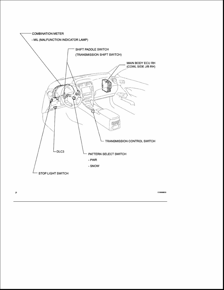
PARTS LOCATION Duration The minimum time that the ECM must sense a continuous deviation in the monitored value(s) before setting a DTC. This timing begins after the "typical enabling conditions" are met. Malfunction thresholds Beyond this value, the ECM will conclude that there is a malfunction and set a DTC. MIL operation MIL illumination timing after a defect is detected. "Immediately" means that the ECM illuminates MIL the instant the ECM determines that there is a malfunction. "2 driving cycle" means that the ECM illuminates MIL if the same malfunction is detected again in the 2nd driving cycle. Component operating range Normal operation range of sensors and solenoids under normal driving conditions. Use these ranges as a reference. They cannot be used to judge if a sensor or solenoid is defective or not.
Fig. 1: Identifying Automatic Transmission System Parts Location (1 Of 2) Courtesy of TOYOTA MOTOR SALES, U.S.A., INC.
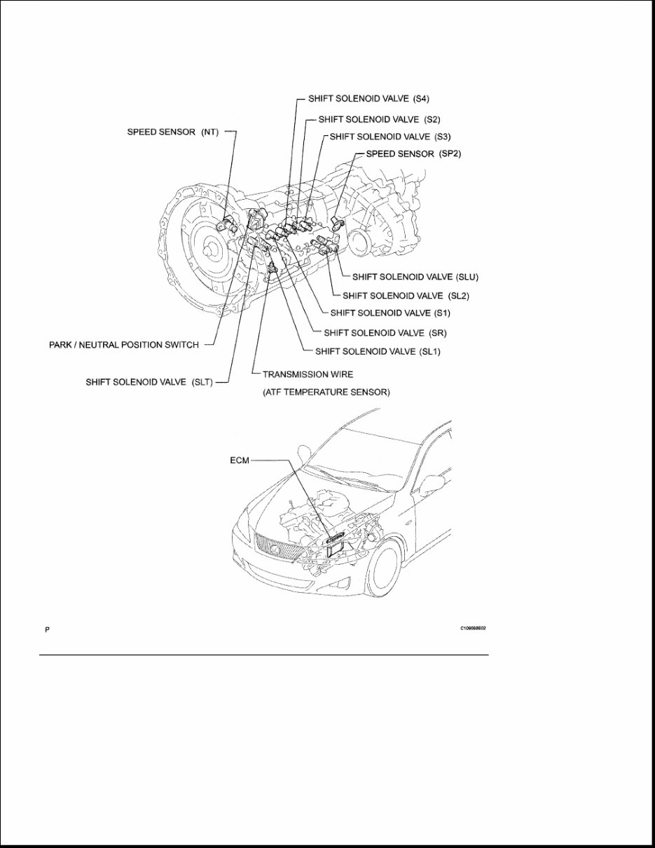
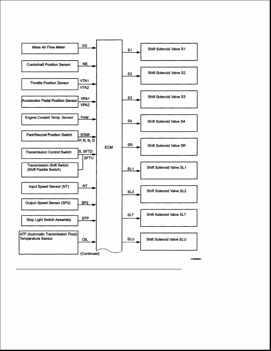
Fig. 2: Identifying Automatic Transmission System Parts Location (2 Of 2) Courtesy of TOYOTA MOTOR SALES, U.S.A., INC. SYSTEM DIAGRAM The configuration of the electronic control system in the A760H automatic transmission is as shown in the following chart.
Fig. 3: Automatic Transmission System - System Diagram (1 Of 2) Courtesy of TOYOTA MOTOR SALES, U.S.A., INC.
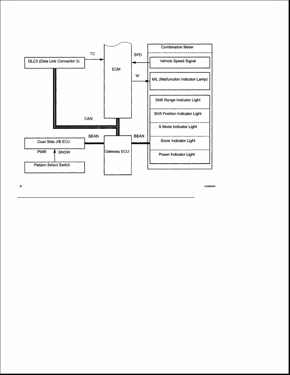
Fig. 4: Automatic Transmission System - System Diagram (2 Of 2) Courtesy of TOYOTA MOTOR SALES, U.S.A., INC.
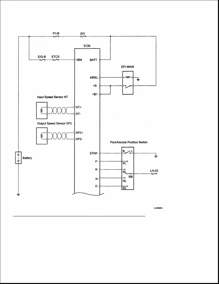
Fig. 5: Automatic Transmission System - Circuit Diagram (1 Of 2) Courtesy of TOYOTA MOTOR SALES, U.S.A., INC.
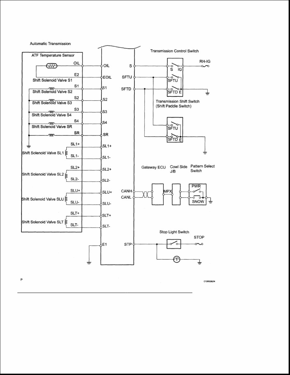
Fig. 6: Automatic Transmission System - Circuit Diagram (2 Of 2) Courtesy of TOYOTA MOTOR SALES, U.S.A., INC. SYSTEM DESCRIPTION 1. SYSTEM DESCRIPTION a. The ECT (Electronic controlled automatic transmission) is an automatic transmission that electronically controls shift timing using the ECM. The ECM detects electrical signals that
If you are in need of a repair manual for your 2006 Lexus IS350, look no further. Our accessible repair manual software is perfect for both professional mechanics and DIY enthusiasts. In the past, traditional service manuals in book format were costly and inconvenient. Our repair manual software provides the same information at a much lower cost and with greater convenience.
Whether you need to fix the brakes, replace suspension components, get the engine running, or perform standard maintenance, this manual has got you covered. It includes comprehensive service information for the brakes, engine, suspension, steering, drivetrain, electrical systems, heating, air conditioning, and more.
By utilizing this repair manual software, you can save a significant amount of money on vehicle maintenance. Mechanics often charge high fees for repairs, but with this manual, you can perform the work yourself. The software is compatible with Windows, Mac computers, smartphones, and tablets, making it easy to access and use.