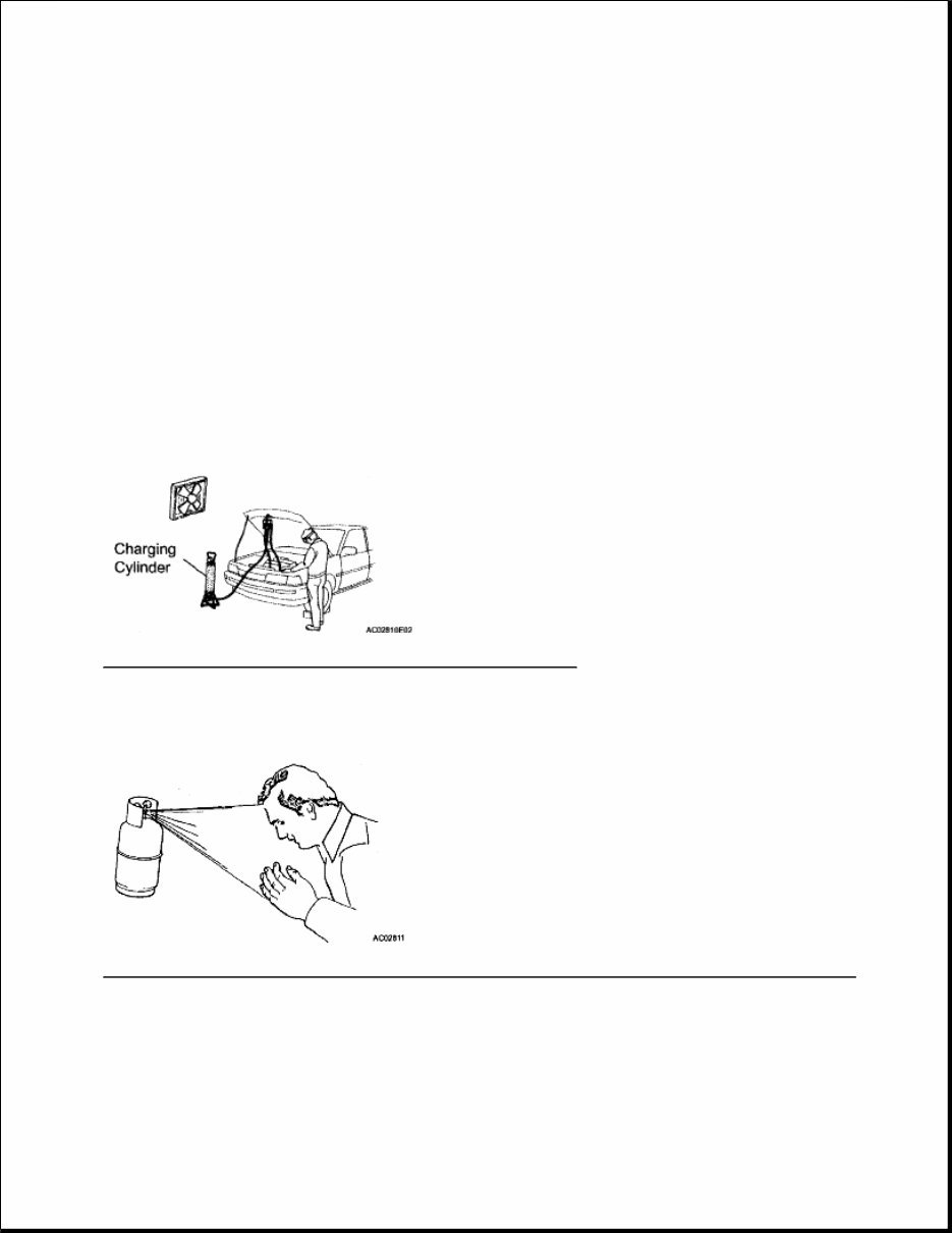
HVAC Air Conditioning - GX 470 AIR CONDITIONING SYSTEM PRECAUTION 1. DO NOT HANDLE REFRIGERANT IN AN ENCLOSED AREA OR NEAR AN OPEN FLAME. 2. ALWAYS WEAR EYE PROTECTION Fig. 1: Identifying Precautions For Wearing Eye Protection Courtesy of TOYOTA MOTOR SALES, U.S.A., INC. 3. BE CAREFUL NOT TO GET LIQUID REFRIGERANT IN YOUR EYES OR ON YOUR SKIN Fig. 2: Identifying Precautions For Getting Liquid Refrigerant In Your Eyes Or On Your Skin Courtesy of TOYOTA MOTOR SALES, U.S.A., INC. If liquid refrigerant gets in your eyes or on your skin: a. Wash the area with lots of cold water. NOTE: Because the compressor operates at high voltages, wear electric insulated gloves and pull out the service plug to cut the high-voltage circuit before inspection. CAUTION: Do not rub your eyes or skin.
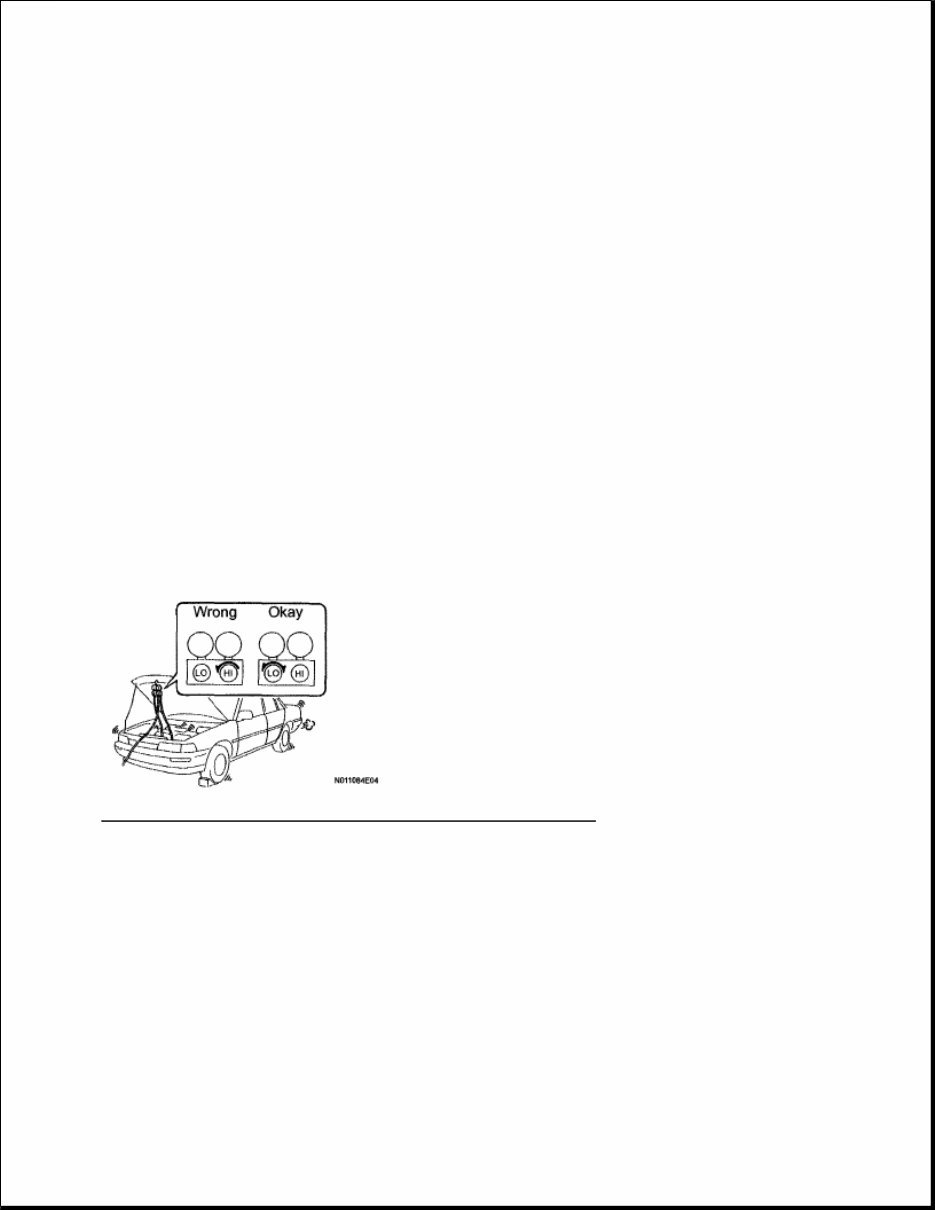
b. Apply clean petroleum jelly to the skin. c. Go immediately to a hospital or see a physician for professional treatment. 4. NEVER HEAT CONTAINER OR EXPOSE IT TO OPEN FLAME 5. BE CAREFUL NOT TO DROP CONTAINER OR APPLY PHYSICAL SHOCKS TO IT 6. DO NOT OPERATE COMPRESSOR WITHOUT ENOUGH REFRIGERANT IN REFRIGERANT SYSTEM If there is not enough refrigerant in the A/C system, oil lubrication will be insufficient and the compressor may be damaged. Necessary care should be taken to avoid this. 7. DO NOT OPEN HIGH PRESSURE MANIFOLD VALVE WHILE COMPRESSOR IS OPERATING Open and close only the low pressure valve. If the high pressure values are opened, refrigerant flows in the reverse direction causing the charging cylinder to rupture. If the high pressure valve is opened, refrigerant flows in the reverse direction causing the charging cylinder to rupture. Fig. 3: Identifying Proper Positions For Operating Compressor Courtesy of TOYOTA MOTOR SALES, U.S.A., INC. 8. BE CAREFUL NOT TO OVERCHARGE SYSTEM WITH REFRIGERANT If refrigerant is overcharged, it causes problems such as insufficient cooling, poor fuel economy, engine overheating, etc. 9. GENERAL PRECAUTION a. While using the battery during inspection, do not bring the positive and negative tester probes too close to each other as a short circuit may occur. PARTS LOCATION
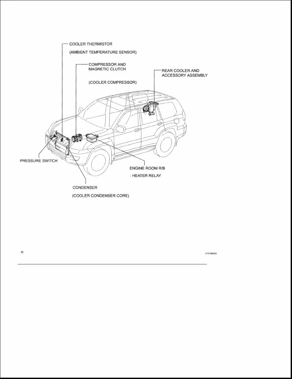
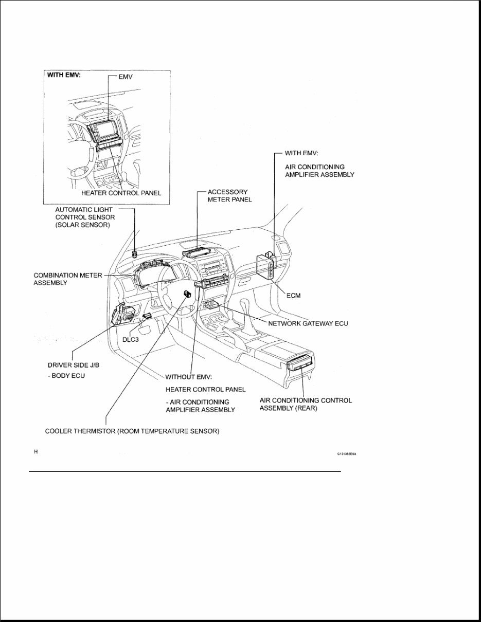
Fig. 4: Identifying Air Conditioner System Replacement Components (1 Of 4) Courtesy of TOYOTA MOTOR SALES, U.S.A., INC.
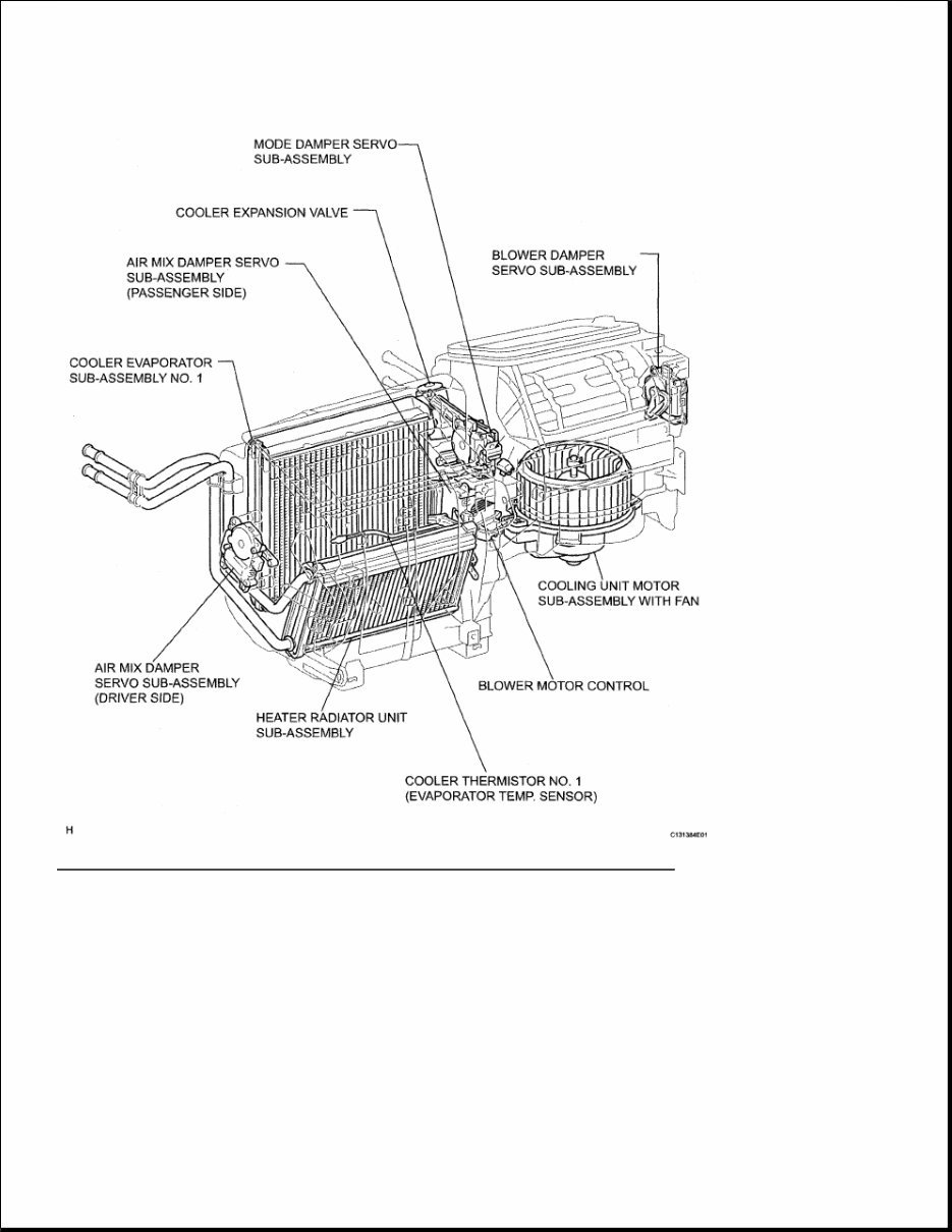
Fig. 5: Identifying Air Conditioner System Replacement Components (2 Of 4) Courtesy of TOYOTA MOTOR SALES, U.S.A., INC.
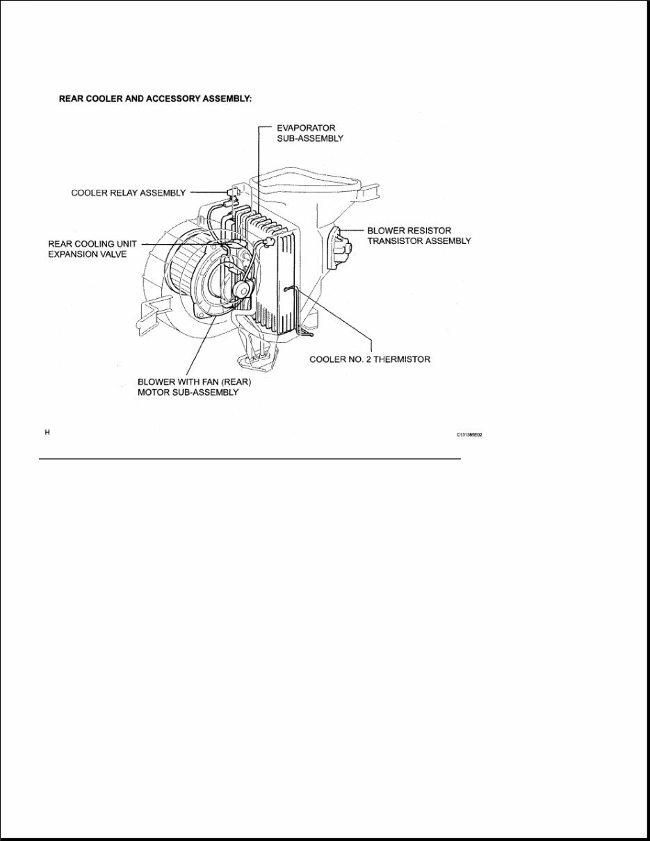
Fig. 6: Identifying Air Conditioner System Replacement Components (3 Of 4) Courtesy of TOYOTA MOTOR SALES, U.S.A., INC.
Fig. 7: Identifying Air Conditioner System Replacement Components (4 Of 4) Courtesy of TOYOTA MOTOR SALES, U.S.A., INC. HOW TO PROCEED WITH TROUBLESHOOTING The intelligent tester can be used in steps 2, 5, 6, 7 and 10. 1. VEHICLE BROUGHT TO WORKSHOP 2. CHECK AND CLEAR DTCS 3. PROBLEM SYMPTOM CONFIRMATION SYMPTOM DOES NOT OCCUR (GO TO STEP 4) SYMPTOM OCCURS (GO TO STEP 5) 4. SYMPTOM SIMULATION 5. DTC CHECK (OTHER THAN MULTIPLEX DTC) TROUBLE CODE (GO TO STEP 6) NORMAL SYSTEM CODE (GO TO STEP 7)
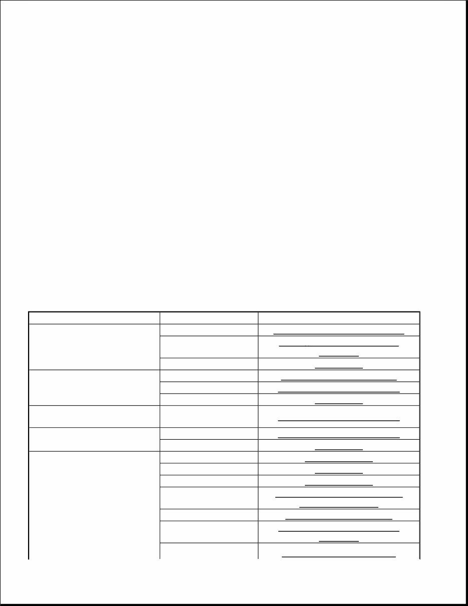
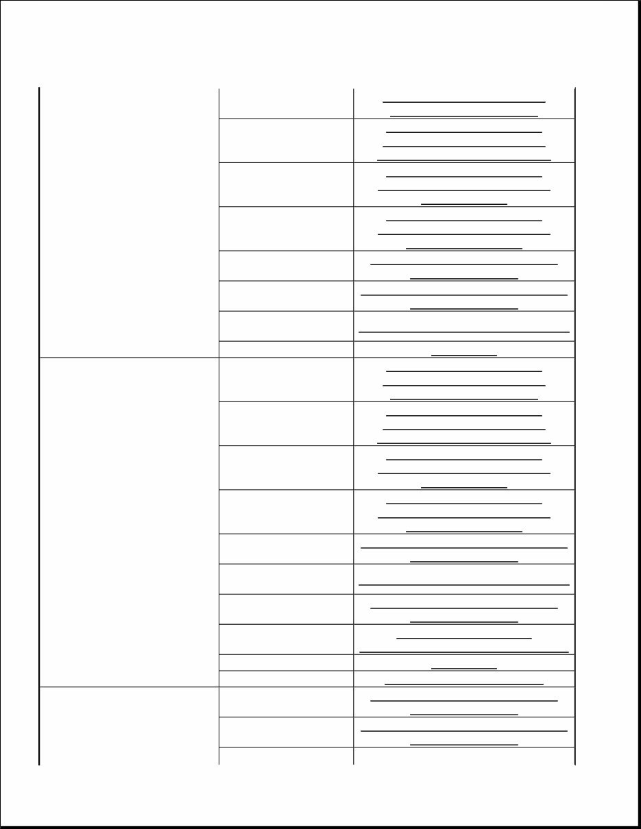
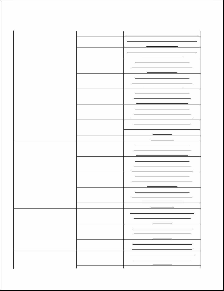
6. DTC CHART GO TO STEP 8 7. PROBLEM SYMPTOMS TABLE 8. ACTUATOR CHECK 9. CIRCUIT INSPECTION 10. TERMINALS OF ECU 11. IDENTIFICATION OF PROBLEM 12. REPAIR OR REPLACE 13. CONFIRMATION TEST NEXT: END PROBLEM SYMPTOMS TABLE If the normal code is displayed during DTC check although the problem still occurs, check the circuits for each problem symptom in the order given in the table below, and proceed to the relevant troubleshooting. Front A/C PROBLEM SYMPTOMS TABLE Symptom Suspected Area Information Whole functions of the A/C system does not operate. IG power source circuit IG POWER SOURCE CIRCUIT Back-up power source circuit BACK - UP POWER SOURCE CIRCUIT A/C amplifier REMOVAL Air Flow Control: No blower operation Heater relay circuit HEATER RELAY CIRCUIT Blower motor circuit BLOWER MOTOR CIRCUIT A/C amplifier REMOVAL Air Flow Control: No blower control Blower motor circuit BLOWER MOTOR CIRCUIT Air Flow Control: Insufficient air out Blower motor circuit BLOWER MOTOR CIRCUIT A/C amplifier REMOVAL Volume of refrigerant REFRIGERANT Drive belt tension REMOVAL Refrigerant pressure REFRIGERANT Compressor lock sensor circuit DTC 22 COMPRESSOR LOCK SENSOR CIRCUIT Compressor circuit COMPRESSOR CIRCUIT Pressure switch circuit DTC 23 PRESSURE SWITCH CIRCUIT Air mix control servo DTC 46 AIR MIX DAMPER
Temperature Control: No cool air comes out. motor circuit (Driver side) CONTROL SERVO MOTOR CIRCUIT (DRIVER SIDE) Air mix control servo motor circuit (Passenger side) DTC 41 AIR MIX DAMPER CONTROL SERVO MOTOR CIRCUIT (PASSENGER SIDE) Air mix damper position sensor circuit (Driver side) DTC 36 AIR MIX DAMPER POSITION SENSOR CIRCUIT (DRIVER SIDE Air mix damper position sensor circuit (Passenger side) DTC 31 AIR MIX DAMPER POSITION SENSOR CIRCUIT (PASSENGER SIDE) Room temp. sensor circuit DTC 11 ROOM TEMPERATURE SENSOR CIRCUIT Ambient temp. sensor circuit DTC 12 AMBIENT TEMPERATURE SENSOR CIRCUIT Vehicle speed signal circuit VEHICLE SPEED SIGNAL CIRCUIT A/C amplifier REMOVAL Temperature Control: No warm air comes out. Air mix control servo motor circuit (Driver side) DTC 46 AIR MIX DAMPER CONTROL SERVO MOTOR CIRCUIT (DRIVER SIDE) Air mix control servo motor circuit (Passenger side) DTC 41 AIR MIX DAMPER CONTROL SERVO MOTOR CIRCUIT (PASSENGER SIDE) Air mix damper position sensor circuit (Driver side) DTC 36 AIR MIX DAMPER POSITION SENSOR CIRCUIT (DRIVER SIDE Air mix damper position sensor circuit (Passenger side) DTC 31 AIR MIX DAMPER POSITION SENSOR CIRCUIT (PASSENGER SIDE) Ambient temp, sensor circuit DTC 12 AMBIENT TEMPERATURE SENSOR CIRCUIT Vehicle speed signal circuit VEHICLE SPEED SIGNAL CIRCUIT Room temp, sensor circuit DTC 11 ROOM TEMPERATURE SENSOR CIRCUIT Evaporator temp, sensor circuit DTC 13 EVAPORATOR TEMPERATURE SENSOR CIRCUIT A/C amplifier REMOVAL Heater radiator AIR CONDITIONING UNIT Room temp, sensor circuit DTC 11 ROOM TEMPERATURE SENSOR CIRCUIT Ambient temp, sensor circuit DTC 12 AMBIENT TEMPERATURE SENSOR CIRCUIT Vehicle speed signal
Temperature Control: Output air is warmer or cooler circuit VEHICLE SPEED SIGNAL CIRCUIT Solar sensor circuit (Driver side) DTC 24 SOLAR SENSOR CIRCUIT (DRIVER SIDE) Solar sensor circuit (Passenger side) DTC 21 SOLAR SENSOR CIRCUIT (PASSENGER SIDE) Air mix damper position sensor circuit (Driver side) DTC 36 AIR MIX DAMPER POSITION SENSOR CIRCUIT (DRIVER SIDE Air mix damper position sensor circuit (Passenger side) DTC 31 AIR MIX DAMPER POSITION SENSOR CIRCUIT (PASSENGER SIDE) Air mix control servo motor circuit (Driver side) DTC 46 AIR MIX DAMPER CONTROL SERVO MOTOR CIRCUIT (DRIVER SIDE) 9. Air mix control servo motor circuit (Passenger side) DTC 41 AIR MIX DAMPER CONTROL SERVO MOTOR CIRCUIT (PASSENGER SIDE) Engine coolant temperature communication circuit DTC 14 ENGINE COOLANT TEMPERATURE COMMUNICATION CIRCUIT A/C amplifier REMOVAL Temperature Control: No temperature control (only Air mix control servo motor circuit (Driver side) DTC 46 AIR MIX DAMPER CONTROL SERVO MOTOR CIRCUIT (DRIVER SIDE) Air mix control servo motor circuit (Passenger side) DTC 41 AIR MIX DAMPER CONTROL SERVO MOTOR CIRCUIT (PASSENGER SIDE) Air mix damper position sensor circuit (Driver side) DTC 36 AIR MIX DAMPER POSITION SENSOR CIRCUIT (DRIVER SIDE Air mix damper position sensor circuit (Passenger side) DTC 31 AIR MIX DAMPER POSITION SENSOR CIRCUIT (PASSENGER SIDE) A/C amplifier REMOVAL No air inlet control Air outlet damper control servo motor circuit DTC 43 AIR OUTLET DAMPER CONTROL SERVO MOTOR CIRCUIT Air inlet damper position sensor circuit DTC 42 AIR INLET DAMPER CONTROL SERVO MOTOR CIRCUIT A/C amplifier DTC 32 AIR INLET DAMPER POSITION SENSOR CIRCUIT Air outlet damper control servo motor circuit DTC 43 AIR OUTLET DAMPER CONTROL SERVO MOTOR CIRCUIT
If you are in need of a repair manual for your 2003 Lexus GX470, look no further. Our accessible repair manual is a cost-effective and convenient alternative to traditional paper manuals. Whether you are a professional mechanic or a DIY enthusiast, this manual covers all the essential service and repair information for the Lexus GX470.
Gone are the days of purchasing expensive traditional service manuals in book format. Our digital manual provides the same valuable information at a fraction of the cost, making it easier and more affordable to access the necessary details for maintaining and repairing your vehicle.
Whether you are tackling brake repairs, suspension component replacements, engine troubleshooting, or standard maintenance tasks, this repair manual is designed to meet your needs. It contains comprehensive service information for brakes, engine, suspension, steering, drivetrain, electrical systems, heating, air conditioning, and more.
By utilizing this manual, you can save a significant amount of money on vehicle repairs. Professional mechanics often charge high fees for their services, but with this , you can take on the repairs yourself and benefit from detailed guidance specific to the 2003 Lexus GX470.
Our repair manual is user-friendly and compatible with Windows, Mac computers, smartphones, and tablets, ensuring easy access to the manual whenever and wherever you need it.




 Lifetime Access




