2 A INTRODUCTION This manual consists of the following 11 sections: A B C D E F G H I J K No. GROUND POINTS OVERALL ELECTRICAL WIRING DIAGRAM SYSTEM CIRCUITS INDEX POWER SOURCE (Current Flow Chart) ELECTRICAL WIRING ROUTING RELAY LOCATIONS GLOSSARY OF TERMS AND SYMBOLS ABBREVIATIONS TROUBLE– SHOOTING HOW TO USE THIS MANUAL INTRODUCTION INDEX Section Description Index of the contents of this manual. Brief explanation of each section. Instructions on how to use this manual. Describes the basic inspection procedures for electrical circuits. Defines the abbreviations used in this manual. Defines the symbols and functions of major parts. Shows position of the Electronic Control Unit, Relays, Relay Block, etc. This section is closely related to the system circuit. Describes position of Parts Connectors, Splice points, Ground points, etc. This section is closely related to the system circuit. Describes power distribution from the power supply to various electrical loads. Index of the system circuits. Electrical circuits of each system are shown from the power supply through ground points. Wiring connections and their positions are shown and classified by code according to the connection method. (Refer to the section, “How to sue this manual”). The “System Outline” and “Service Hints” useful for troubleshooting are also contained in this section. Shows ground positions of all the parts decribed in this manual. Provides circuit diagrams showing the circuit connections.
3 HOW TO USE THIS MANUAL B This manual provides information on the electrical circuits installed on vehicles by dividing them into a circuit for each system. The actual wiring of each system circuit is shown from the point where the power source is received from the battery as far as each ground point. (All circuit diagrams are shown with the switches in the OFF position.) When troubleshooting any problem, first understand the operation of the circuit where the problem was detected (see System Circuit section), the power source supplying power to that circuit (see Power Source section), and the ground points (see Ground Points section). See the System Outline to understand the circuit operation. When the circuit operation is understood, begin troubleshooting of the problem circuit to isolate the cause. Use Relay Location and Electrical Wiring Routing sections to find each part, junction block and wiring harness connectors, wiring harness and wiring harness connectors, splice points, and ground points of each system circuit. Internal wiring for each junction block is also provided for better understanding of connection within a junction block. Wiring related to each system is indicated in each system circuit by arrows (from ,to ). When overall connections are required, see the Overall Electrical Wiring Diagram at the end of this manual.
* The system shown here is an EXAMPLE ONLY. It is different to the actual circuit shown in the SYSTEM CIRCUITS SECTION. 4 B HOW TO USE THIS MANUAL
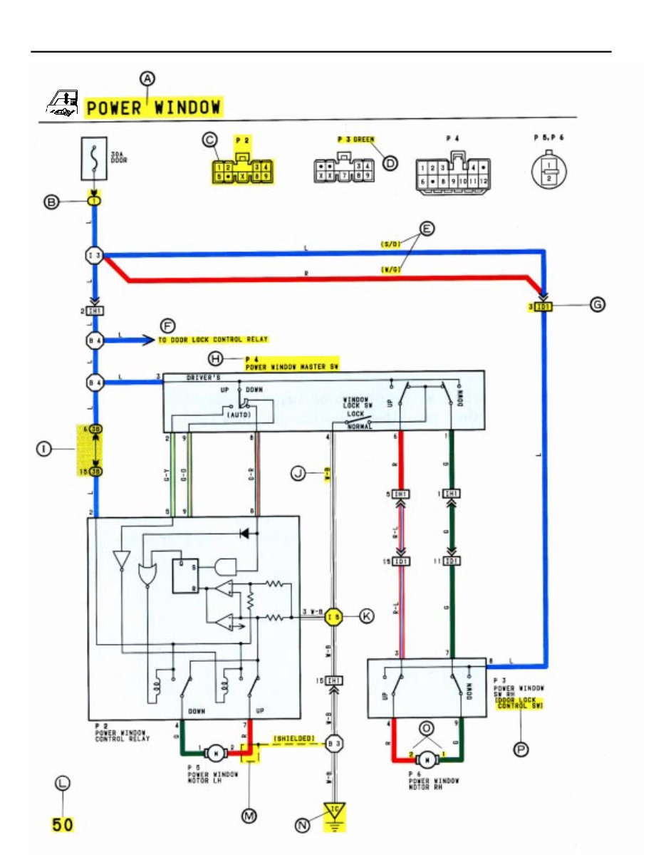
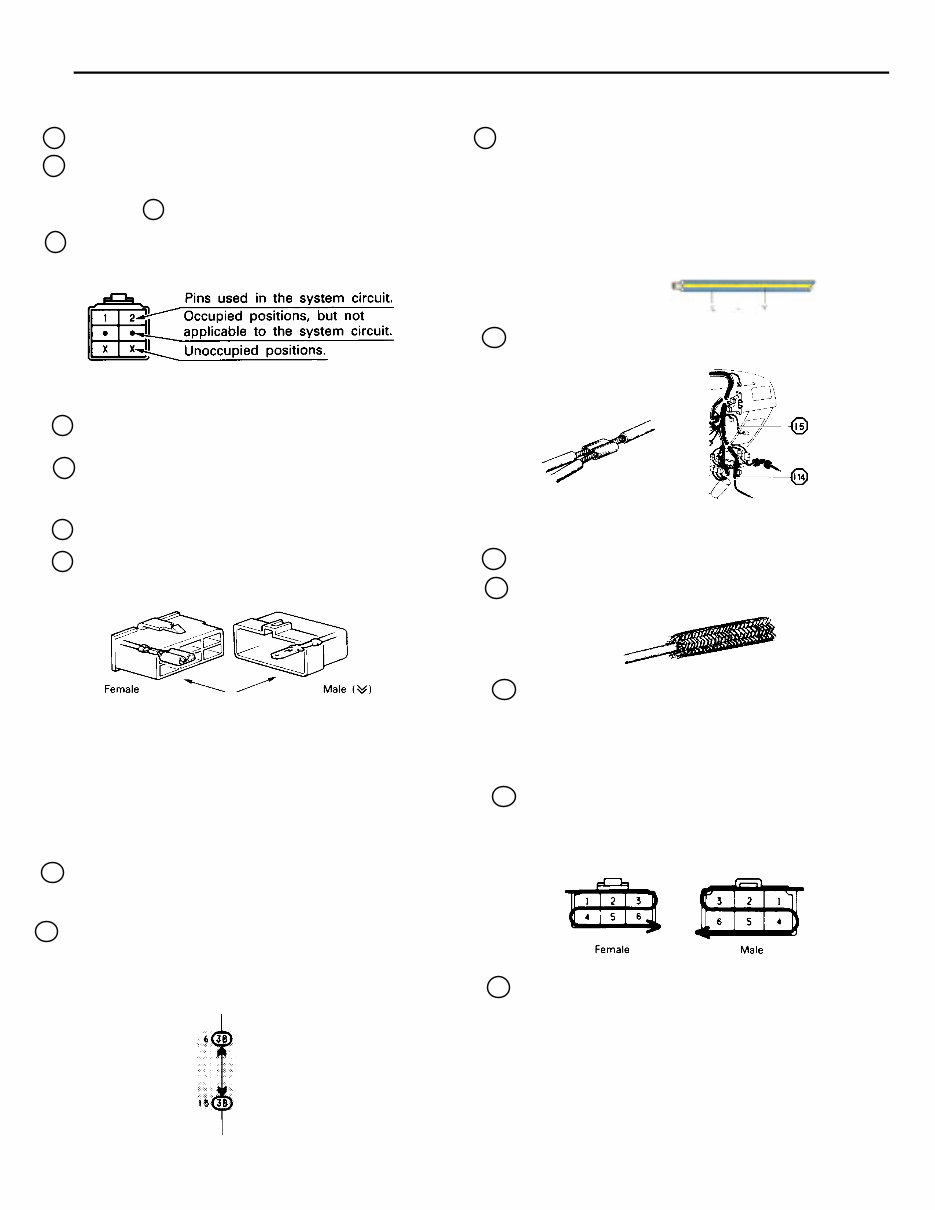
5 B I : Junction Block (The number in the circle is the J/B No. and the connector code is shown beside it). Junction Blocks are shaded to clearly separate them from other parts (different junction blocks are shaded differently for further clarification). A : System Title B : Indicates a Relay Block. No shading is used and only the Relay Block No. is shown to distinguish it from the J/B. Example: 1 Indicates Relay Block No. 1. C : Indicates the connector to be connected to a part (the numeral indicates the pin No.) Explanation of pin use. J : Indicates the wiring color. Wire colors are indicated by an alphabetical code. B = Black BR = Brown G = Green GR = Gray L = Black LG = Light Green O = Orange P = Pink R = Red V = Violet W = White Y = Yellow The first letter indicates the basic wire color and the second letter indicates the color of the stripe. D : Connector Color Connectors not indicated are milky white in color: E : ( ) is used to indicate different wiring and connector, etc. when the vehicle model, engine type, or specification is different. F : Indicates related system. G : Indicates the wiring harness and wiring harness connector. The wiring harness with male terminal is shown with arrows ( ). Example: L – Y K : Indicates a wiring Splice Point (Codes are “E” for the Engine Room, “I” for the Instrument Panel, and “B” for the Body). Example: The Location of Splice Point I 5 is indicated by the shaded section. L : Page No. M : Indicates a shielded cable. Example: N : Indicates a ground point. The first letter of the code for each ground point(s) indicates the component’s location, e.g. “E” for the Engine Compartment, “I” for the Instrument Panel and Surrounding area, and “B” for the Body and Surrounding area. The first letter of the code for each wiring harness and wiring harness connector(s) indicates thecomponent’s location, e.g, “E” for the Engine Compartment, “I” for the Instrument Panel and Surrounding area, and “B” for the Body and Surrounding area. When more than one code has the first and second letters in common, followed by numbers (e.g, IH1, IH2), this indicates the same type of wiring harness and wiring harness connector. P : When 2 parts both use one connector in common, the parts connector name used in the wire routing section is shown in square brackets [ ]. O : Indicates the pin number of the connector. The numbering system is different for female and male connectors. H : Represents a part (all parts are shown in sky blue). The code is the same as the code used in parts position. 3B indicates that it is inside Junction Block No. 3. v v The pins shown are only for the highest grade, or only include those in the specification. lower right lower left (blue) (yellow)
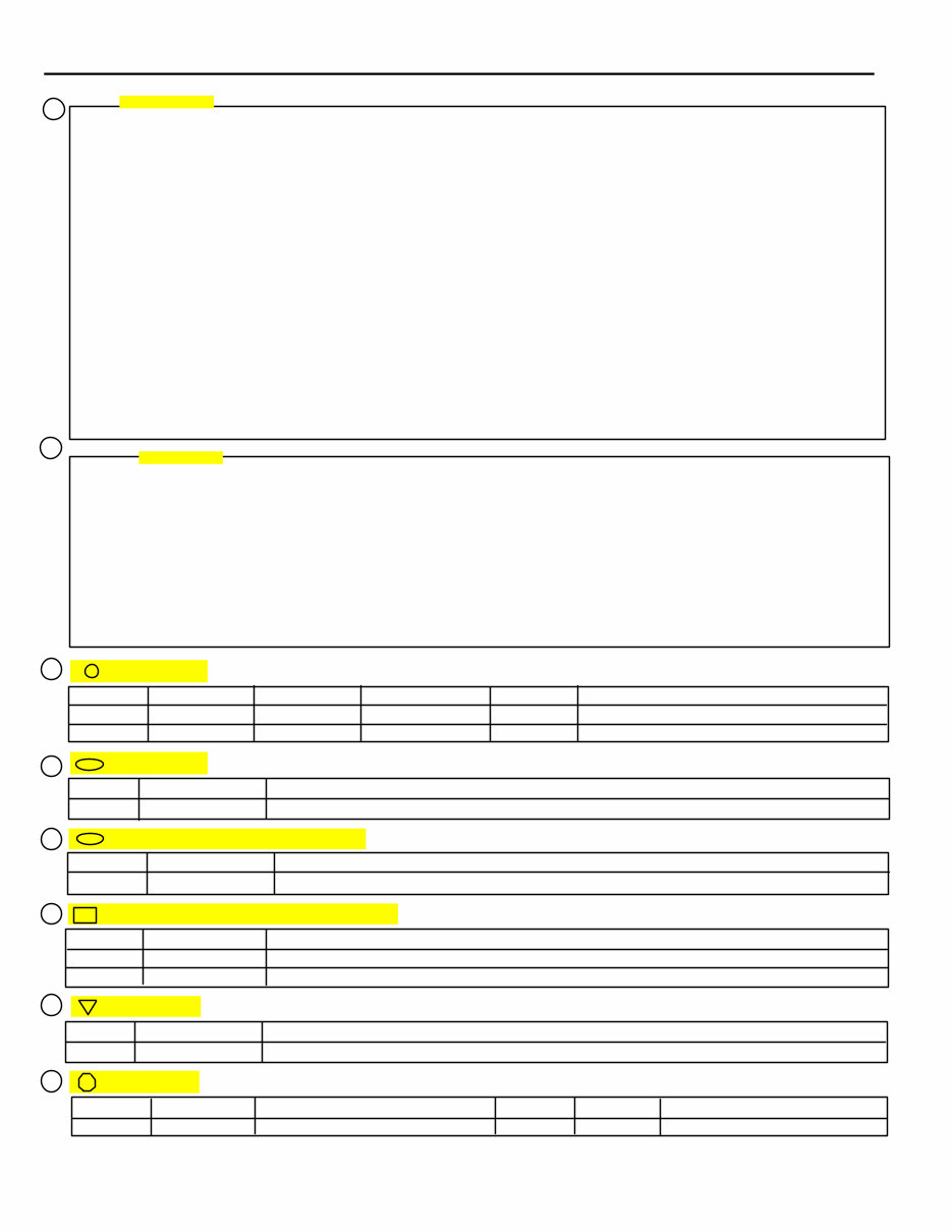
6 B HOW TO USE THIS MANUAL WITH THE IGNITION SW TURNED ON, THE CURRENT FLOWS TO TERMINAL 3 OF THE POWER WINDOW MASTER SW, TERMINAL 2 OF THE POWER WINDOW CONTROL RELAY AND TERMINAL 8 OF THE POWER WINDOW SW THROUGH THE DOOR FUSE. 1. DRIVER’S WINDOW “MANUAL UP” OPERATION BY MASTER SW HOLDING MANUAL SW (DRIVER’S) ON “UP” POSITION LOCATED IN POWER WINDOW MASTER SW, THE CURRENT FLOWS TO TERMINAL 5 OF THE POWER WINDOW CON- TROL RELAY THROUGH TERMINAL 3 OF THE MASTER SW Ô TERMINAL 2 TO OPERATE A POWER WINDOW CONTROL RELAY. THUS THE CURRENT INSIDE THE RELAY FLOWS FROM TERMINAL 2 OF THE RELAY Ô TERMINAL 1 Ô TERMINAL 2 OF THE POWER WINDOW MOTOR Ô TERMINAL 1 Ô TERMINAL 4 OF THE RELAY Ô TERMI- NAL 3 Ô TO GROUND. THE MOTOR TURNS TO ASCENT THE WINDOW. RELEASING THIS SW, THE ROTATION OF MOTOR IS STOPPED AND THE WINDOWS CAN STOP AT WILL POINT. (FOR THE “MANUAL DOWN” OPERATION, CURRENT FLOWS IN THE REVERSE DIRECTION BECAUSE THE TERMINALS WHERE IT FLOW ARE CHANGED). 2. DRIVER’S WINDOW “AUTO DOWN” OPERATION BY MASTER SW ONCE THE “AUTO DOWN” BUTTON OF THE MASTER SW IS PUSHED, THE CURRENT FLOW TERMINAL 9 OF THE POWER WINDOW CONTROL RELAY THROUGH TERMINAL 3 OF THE MASTER SWÔ TERMINALS 8 AND 9 TO OPERATE THE RELAY. THUS THE CURRENT INSIDE THE POWER WINDOW CONTROL RELAY FLOWS FROM TERMINAL 2 OF THE RELAY Ô TERMINAL 4 Ô TERMINAL 1 OF THE POWER WINDOW MOTOR Ô TERMINAL 2 Ô TERMINAL 1 OF THE RELAY Ô TERMINAL 3 Ô TO GROUND. THE MOTOR CONTINUES THE ROTATION ENABLING TO DESCENT THE WINDOW. THE WINDOW DESCENDS TO THE END POSITION. THE CURRENT WILL BE CUT OFF TO RELEASE THE AUTO DOWN FUNCTION BASED ON THE INCREASING CURRENT BETWEEN TERMINAL 2 OF THE RELAY AND TERMINAL 1 IN RELAY. 3. DRIVER’S WINDOW AUTO DOWN RELEASE OPERATION BY MASTER SW HOLDING THE MANUAL SW (DRIVER’S) ON “UP” POSITION IN OPERATING AUTO DOWN. THE CURRENT FROM TERMINAL 3 OF THE MASTER SW PASSING TERMINAL 2 FLOWS TERMINAL 5 OF THE RELAY AND RELEASES THE AUTO DOWN FUNCTION IN THE POWER WINDOW CONTROL RELAY. RELEASING THE HAND FROM SW, WINDOW STOPS AND CONTINUING ON TOUCHING SW. THE FUNCTION SWITCHES TO MANUAL UP OPERATION. 4. PASSENGER’S WINDOW UP OPERATION (MASTER SW) AND WINDOW LOCK SW OPERATION HOLDING PASSENGER’S WINDOW SW (MASTER SW) ON “UP”, THE CURRENT FLOWS FROM TERMINAL 3 OF THE MASTER SW PASSING TERMINAL 6 TO TERMINAL 3 OF THE POWER WINDOW SW (PASSENGER’S) Ô TERMINAL 4 TERMINAL Ô 2 OF THE MOTOR Ô TERMINAL 1 Ô TERMINAL 9 OF THE POWER WINDOW SW Ô TERMINAL 7 Ô TERMINAL 1 OF THE MASTER SW Ô TERMINAL 4 TO GROUND. THE MOTOR RUNS TO ASCENT THE WINDOW. RELEASING THIS SW, THE ROTATION OF MOTOR IS STOPPED AND WINDOW CAN STOP AT WILL PLACE. SWITCHING THE WINDOW LOCK SW IN “LOCK” POSITION, THE CIRCUIT IS OPENED AND STOPPED THE MOTOR ROTA- TION. (FOR THE DOWN OPERATION, CURRENT FLOWS IN THE REVERSE DIRECTION BECAUSE THE TERMINALS WHERE IT FLOWS ARE CHANGED). P 2 POWER WINDOW CONTROL RELAY 3–GROUND: ALWAYS CONTINUITY 2–GROUND: APPROX. 12 VOLTS WITH THE IGNITION SW AT ON POSITION 5–GROUND: APPROX. 12 VOLTS WITH THE IGNITION SW AT ON POSITION AND THE MASTER SW AT UP POSITION 8–GROUND: APPROX. 12 VOLTS WITH THE IGNITION SW AT ON POSITION AND THE MASTER SW AT AUTO DOWN POSITION 9–GROUND: APPROX. 12 VOLTS WITH THE IGNITION SW AT ON POSITION AND THE MASTER SW AT DOWN OR AUTO DOWN POSITION P 4 POWER WINDOW MASTER SW 4–GROUND: ALWAYS CONTINUITY 3–GROUND: APPROX. 12 VOLTS WITH THE IGNITION SW AT ON POSITION WINDOW LOCK SW OPEN WITH THE WINDOW LOCK SW AT LOCK POSITION : PARTS LOCATION CODE SEE PAGE CODE SEE PAGE CODE SEE PAGE P2 21 P4 21 P6 21 P3 21 P5 21 : RELAY BLOCKS CODE SEE PAGE RELAY BLOCK (RELAY BLOCK LOCATION) 1 16 R/B NO. 1 (INSTRUMENT PANEL LEFT) : JUNCTION BLOCK AND WIRE HARNESS CONNECTOR CODE SEE PAGE JUNCTION BLOCK AND WIRE HARNESS (CONNECTOR LOCATION) 38 14 J/B NO. 3 AND COWL WIRE (INSTRUMENT PANEL LEFT SIDE) : CONNECTOR JOINING WIRE HARNESS AND WIRE HARNESS CODE SEE PAGE JOINING WIRE HARNESS AND WIRE HARNESS (CONNECTOR LOCATION) ID1 26 FRONT DOOR RH WIRE AND COWL WIRE (RIGHT KICK PANEL) IH1 26 FRONT DOOR LH WIRE AND COWL WIRE (LEFT KICK PANEL) : GROUND POINTS CODE SEE PAGE GROUND POINT LOCATION IC 24 COWL LEFT : SPLICE POINTS CODE SEE PAGE WIRE HARNESS WITH SPLICE POINTS CODE SEE PAGE WIRE HARNESS WITH SPLICE POINTS I 5 24 COWL WIRE Q R S T U V W X SERVICE HINTS SYSTEM OUTLINE
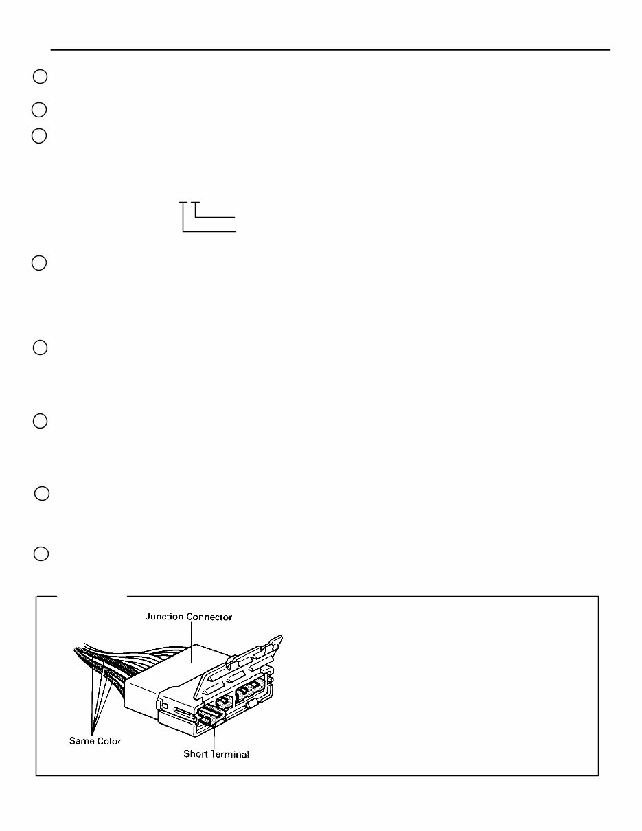
7 B Q : Explains the system outline. R : Indicates values or explain the function for reference during troubleshooting. S : Indicates the reference page showing the position on the vehicle of the parts in the system circuit. Example: Part “P 4” (Power Window Master SW) is on page 21 of the manual. * The letter in the code is from the first letter of the part, and the number indicates its order in parts starting with the letter. Example: P 4 HINTS: Part is 4th in order Power Window Master SW Junction connector (code: J1 to J19) in this manual include a short terminal which is connected to a number of wire harnesses. Always perform inspec- tion with the short terminal installed. (When instal- ling the wire harnesses, the harnesses can be con- nected to any position within the short terminal grouping. Accordingly, in other vehicles, the same position in the short terminal may be connected to a wire harness from a different part.) Wire harness sharing the same short terminal grouping have the same color. T : Indicates the reference page showing the position on the vehicle of Relay Block Connectors in the system circuit. Example: Connector “1” is described on page 16 on this manual and is installed on the left side of the instrument panel. U : Indicates the reference page showing the position on the vehicle of J/B and Wire Harness in the system circuit. Example: Connector “3B”connects the Cowl Wire and J/B No. 3. It is described on page 14 of this manual, and is installed on the instrument panel left side. V : Indicates the reference page describing the wiring harness and wiring harness connector (the female wiring harness is shown first, followed by the male wiring harness). Example: Connector “ID1”connects the front door RH wire (female) and cowl wire (male). It is described on page 26 of this manual, and is installed on the right side kick panel. W : Indicates the reference page showing the position of the ground points on the vehicle. Example: Ground point “IC” is described on page 24 of this manual and is installed on the cowl left side. X : Indicates the reference page showing the position of the splice points on the vehicle. Example: Splice point “I 5” is on the Cowl Wire Harness and is described on page 24 of this manual.
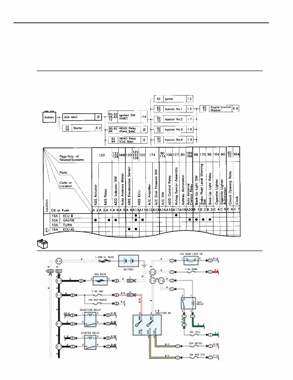
8 B HOW TO USE THIS MANUAL The “Current Flow Chart” section, describes which parts each power source (fuses, fusible links, and circuit breakers) transmits current to. In the Power Source circuit diagram, the conditions when battery power is supplied to each system are explained. Since all System Circuit diagrams start from the power source, the power source system must be fully understood. * The system shown here is an EXAMPLE ONLY. It is different to the actual circuit shown in the SYSTEM CIRCUITS SECTION. H POWER SOURCE (CURRENT FLOW CHART) The chart below shows the route by which current flows from the battery to each electrical source (Fusible Link, Circuit Breaker, Fuse, etc.) and other parts. The next page and following pages shown the parts to which each electrical source outputs current. POWER SOURCE
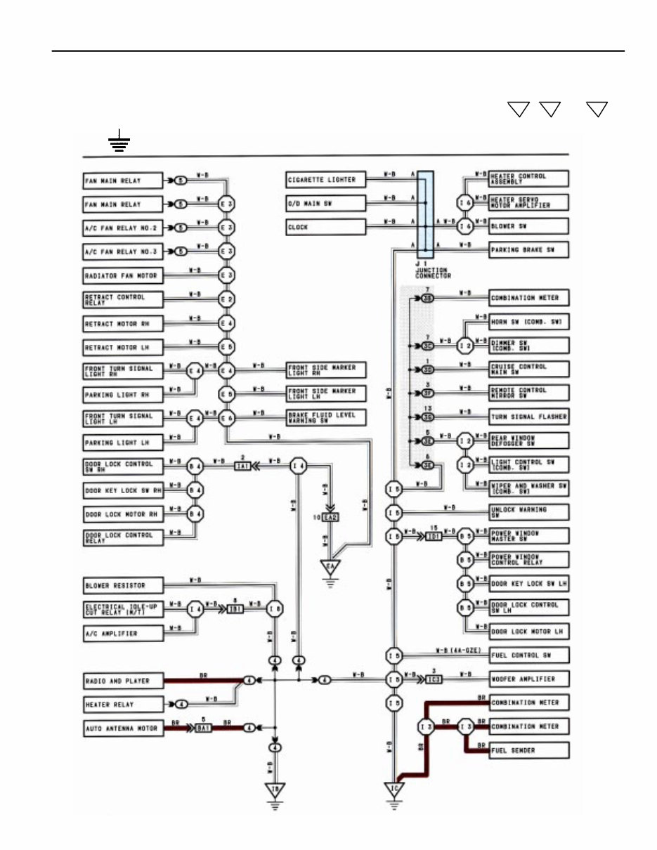
9 B The ground points circuit diagram shows the connections from all major parts to the respective ground points. When troubleshooting a faulty ground point, checking the system circuits which use a common ground may help you identify the problem ground quickly. The relationship between ground points ( , and shown below) can also be checked this way. EA IB IC * The system shown here is an EXAMPLE ONLY. It is different to the actual circuit shown in the SYSTEM CIRCUITS SECTION. J GROUND POINT
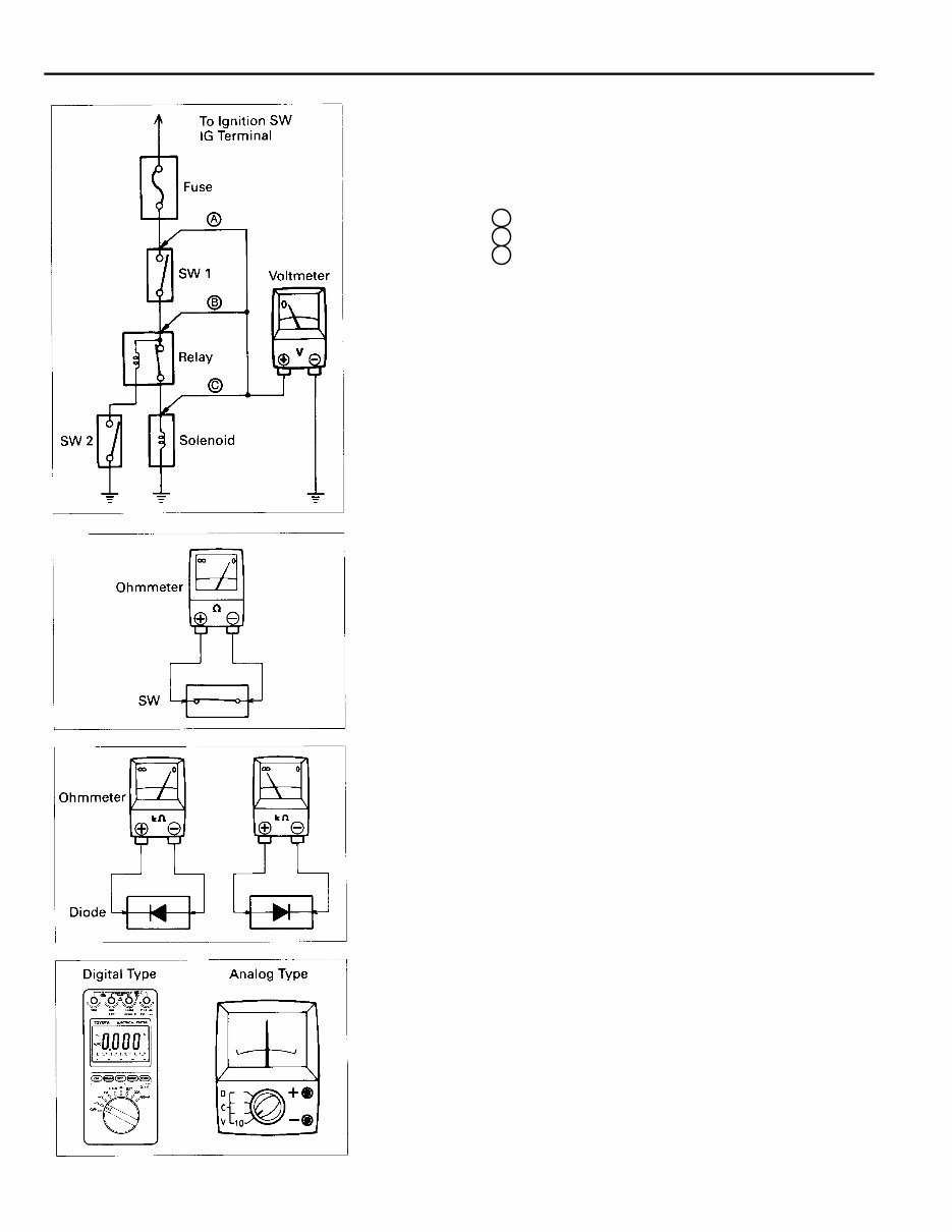
10 C TROUBLESHOOTING (a) Disconnect the battery terminal or wire so there is no voltage between the check points. (b) Contact the two leads of an ohmmeter to each of the check point. If the circuit has diodes, reverse the two leads and check again. When contacting the negative lead to the diode positive side and the positive lead to the negative side, there should be continuity. When contacting the two leads in reverse, there should be no continuity. (c) Use the volt/ohmmeter with high impedance (10kΩ/V minimum) for troubleshooting of the electrical circuit. CONTINUITY AND RESISTANCE CHECK VOLTAGE CHECK (a) Establish conditions in which voltage is check point. Example: A – Ignition SW on B – Ignition SW and SW 1 on C – Ignition SW, SW 1 and Relay on (SW2 off) (b) Using a voltmeter, connect the negative lead to a ground point or negative battery terminal, and a positive lead to the connector or component terminal. This check can be done with a test light instead of a voltmeter.
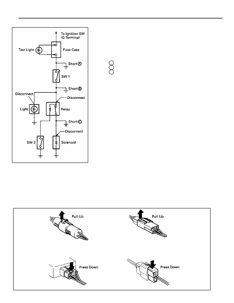
11 C (a) Remove the blown fuse and disconnect all loads of the fuse. (b) Connect a test light in place of the fuse. (c) Establish conditions in which the test light comes on. Example: A – Ignition SW on B – Ignition SW and SW 1 on C – Ignition SW, SW 1 and Relay on (Connect the Relay) and SW 2 off (or Disconnect SW 2) (d) Disconnect and reconnect the connectors while watching the test light. The short lies between the connector where the test light stays lit and the connector where the light goes out. (e) Find the exact location of the short by lightly shaking the problem wire along the body. (a) Do not open the cover or the case of the ECU unless absolutely necessary. (If the IC terminals are touched, the IC may be destroyed by static electricity.) (b) When replacing the internal mechanism (ECU part) of the digital meter, be careful that no part of your body or clothing comes in contact with the terminals of leads from the IC, etc. of the replacement part (spare part). CAUTION: FINDING A SHORT CIRCUIT DISCONNECTION OF MALE AND FEMALE CONNECTORS To pull apart the connectors, pull on the connector itself, not the wire harness. HINT: Check to see what kind of connector you are disconnecting before pulling apart.
If you are in need of a repair manual for your 1998 Lexus ES300, look no further. Our accessible repair manual is a cost-effective and convenient alternative to traditional paper manuals. Whether you are a professional mechanic or a DIY enthusiast, this manual covers all the essential service and repair information for the Lexus ES300.
Gone are the days of purchasing expensive traditional service manuals in book format. Our digital manual provides the same valuable information at a fraction of the cost, making it easier and more affordable to access the necessary details for maintaining and repairing your vehicle.
Whether you are tackling brake repairs, suspension component replacements, engine troubleshooting, or standard maintenance tasks, this repair manual is designed to meet your needs. It contains comprehensive guidance on brakes, engine, suspension, steering, drivetrain, electrical systems, heating, air conditioning, and more.
By utilizing this manual, you can save a significant amount of money on vehicle repairs. Professional mechanics often charge high fees for their services, but with this , you have the resources to work on your ES300 independently. The manual is user-friendly and compatible with Windows, Mac computers, smartphones, and tablets, ensuring easy access to the information you require.