


Workshop manual - Range Rover Sport (L320) 2007-09
1/1
Published: 11-Ma\-2011
GeneUal InfoUmaWion - AboXW ThiV ManXal
Description and Operation
NoWeV, CaXWionV and WaUningV
Throughout this manual, important information is highlighted b\ the use of NOTES, CAUTIONS and WARNINGS.
NOTES give additional information on a topic or procedure, CAUTIONS are given to prevent damage to the vehicle,
and WARNINGS are given to prevent personal injur\.
Published: 11-May-2011
General Information - About This Manual
Description and Operation
Introduction
This manual has been written in a format that is designed to meet the needs of technicians worldwide. The objective
is to use common formats and include similar content in each manual.
This manual provides general descriptions for accomplishing diagnosis and testing, service and repair work with
tested and effective techniques. Following them will help to ensure reliability.
Important Safet\ Instructions
Appropriate service methods and correct repair procedures are essential for the safe, reliable operation of all motor
vehicles as well as the personal safety of the individual carrying out the work.
Anyone who departs from the instructions provided in this manual must first establish that personal safety or vehicle
integrity is not compromised by the choice of method, tools or components.
Warnings, Cautions and Notes in This Manual
WARNING: Warnings are used to indicate that failure to follow a procedure correctly may result in personal
injury.
CAUTION: Cautions are used to indicate that failure to follow a procedure correctly may result in damage to the
vehicle or equipment being used.
NOTE: Notes are used to provide additional essential information required to carry out a complete and satisfactory
repair.
Generic warnings or cautions are in their relevant description and operation procedure within section 100-00. If the
generic warnings or cautions are required for a procedure, there will be a referral to the appropriate description and
operation procedure.
If a warning, caution or note only applies to one step, it is placed at the beginning of the specific step.
Trustmark Authoring Standards (TAS) Removal and Installation Procedures
NOTE: TAS style procedures can be identified by steps that have no accompanying step text and the magenta color
of the electrical connectors and fasteners such as nuts, bolts, clamps or clips.
A TAS removal and installation procedure uses a sequence of color illustrations to indicate the order to be followed
when removing/disassembling or installing/assembling a component.
Many of the TAS procedures will have the installation information within the removal steps. These procedures will
have the following note at the beginning of the procedure:
NOTE: Removal steps in this procedure may contain installation details.
Items such as O-ring seals, gaskets, seals, self-locking nuts and bolts are to be discarded and new components
installed unless otherwise stated within the procedure. Coated nuts or bolts are to be reused, unless damaged or
otherwise stated within the procedure.
Specification procedures will contain all technical data that are not part of a repair procedure.
TAS Graphics
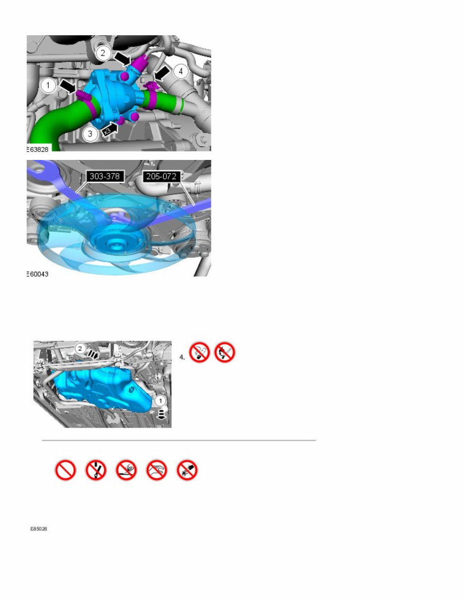
Colors used in the graphic are as follows:
Blue - Indicates the target item, item to be removed/installed or disassembled/assembled
Green and Brown - Indicates a secondary item that needs to be detached, removed/installed or
disassembled/assembled prior to the target item
Magenta - Indicates electrical connectors and fasteners such as nuts, bolts, clamps or clips
Pale Blue - is for the special tool(s) and general equipment.
There may be multiple steps assigned to one illustration.
Numbered pointers are used to indicate the number of electrical connectors and fasteners such as nuts, bolts, clamps
or clips.
IWHPV LQ WKH LOOXVWUDWLRQ FDQ EH WUDQVSDUHQW RU XVH FXWRXWV WR VKRZ KLGGHQ GHWDLO(V).
TAS S\PEROV
S\PEROV DUH XVHG LQVLGH WKH JUDSKLFV DQG LQ WKH WH[W DUHD WR HQKDQFH WKH LQIRUPDWLRQ GLVSOD\. TKH IROORZLQJ
SDUDJUDSKV GHVFULEH WKH YDULRXV W\SHV DQG FDWHJRULHV RI V\PEROV.
PURKLELWLRQ V\PEROV DGYLVH RQ SURKLELWHG DFWLRQV WR HLWKHU DYRLG GDPDJH RU KHDOWK DQG VDIHW\ UHODWHG ULVNV.
HHDOWK DQG SDIHW\ V\PEROV UHFRPPHQG WKH XVH RI SDUWLFXODU SURWHFWLRQ HTXLSPHQW WR DYRLG RU DW OHDVW UHGXFH WKH ULVN
RU VHYHULW\ RI SRVVLEOH LQMXULHV.
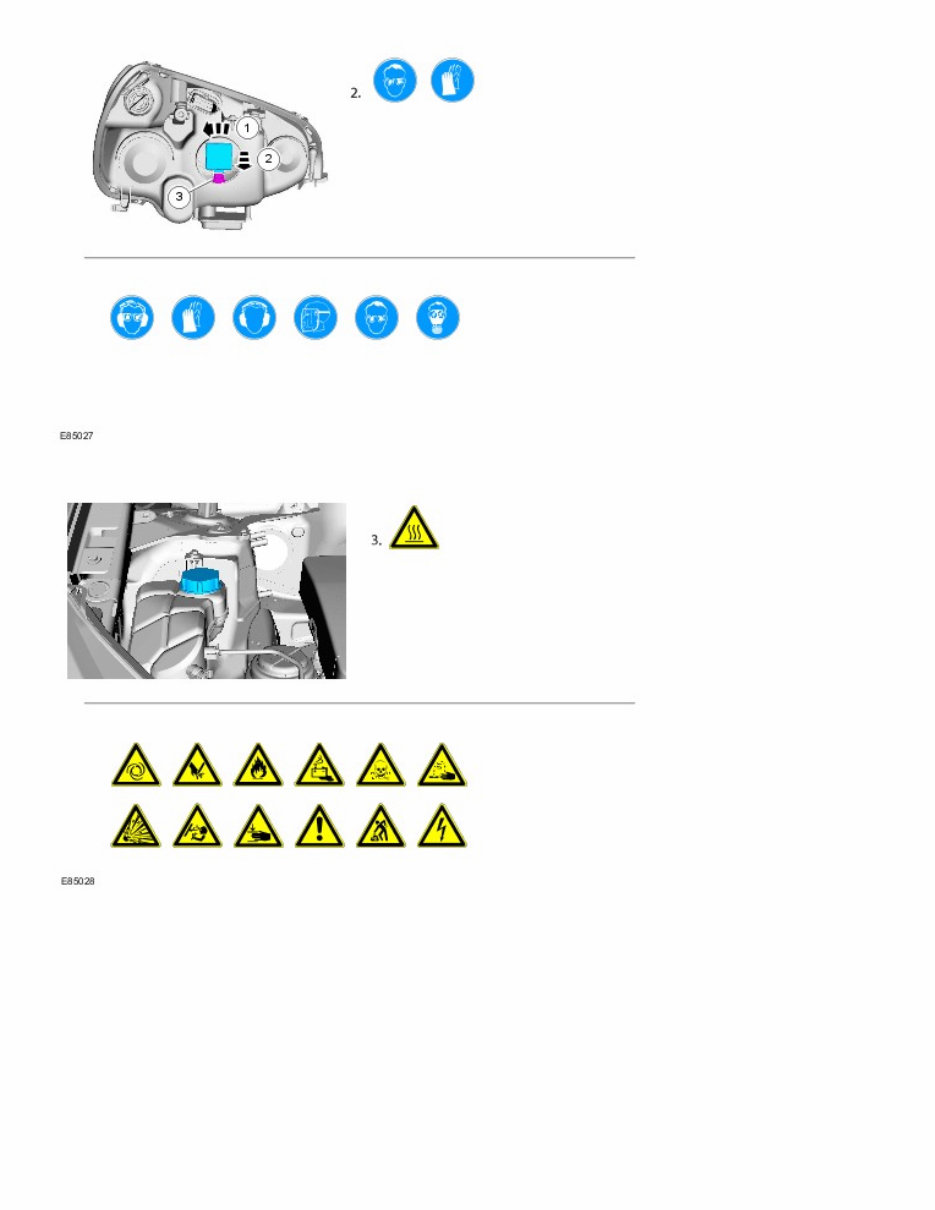
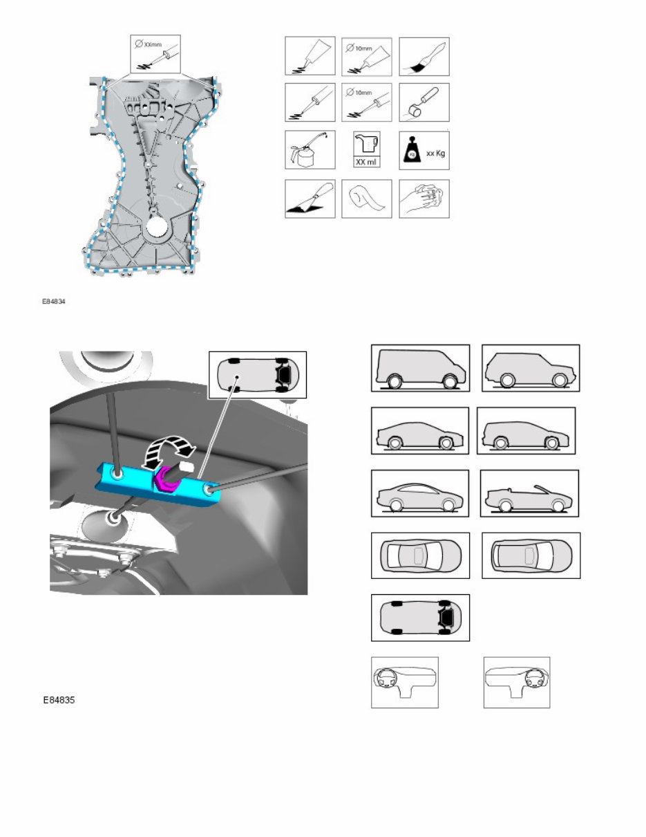
Warning s\mbols are used to indicate potential risks resulting from a certain component or area.
Instruction s\mbols are used to appl\ sealer, lubricant, weight, tape or cleaning detergent to a component.
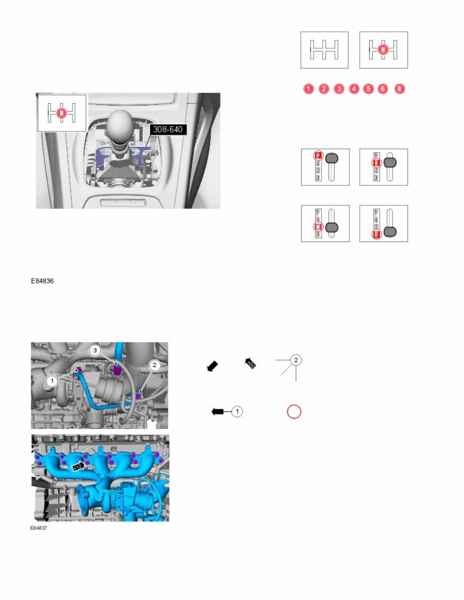
Location s\mbols are used to show the location of a component or s\stem within the vehicle.
Gearshift lever or selector lever position s\mbols are used to show which gearshift lever or selector lever position is
to be set.
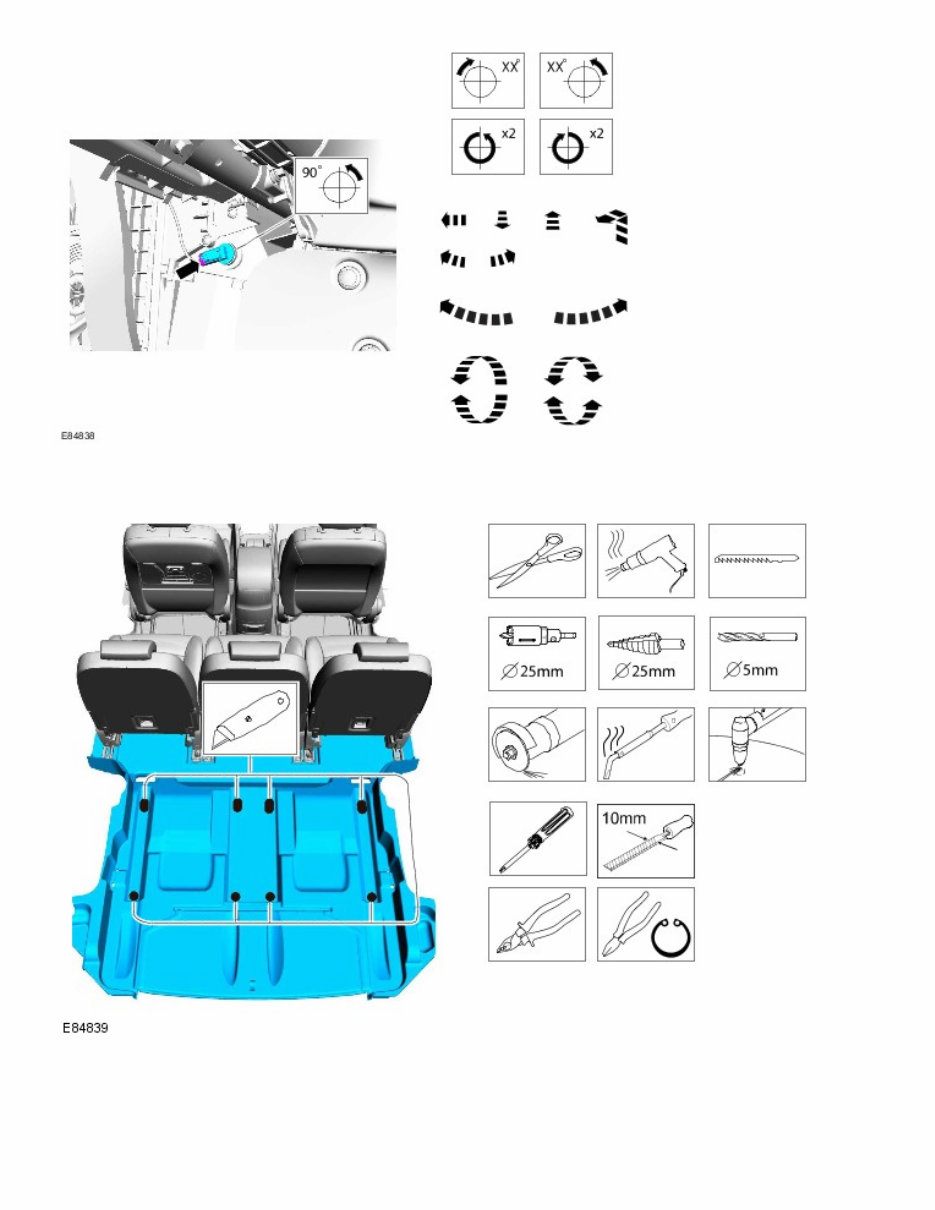
Pointer s\mbols are used to draw the attention to components and give special instructions such as a required
sequence or number of components. The number of components is reflected b\ the value inside the lut\ arrow. A
sequence number is located inside the circle. Numbers inside circles are also used to allocate special information such
as tightening torques or chemicals to a particular component.
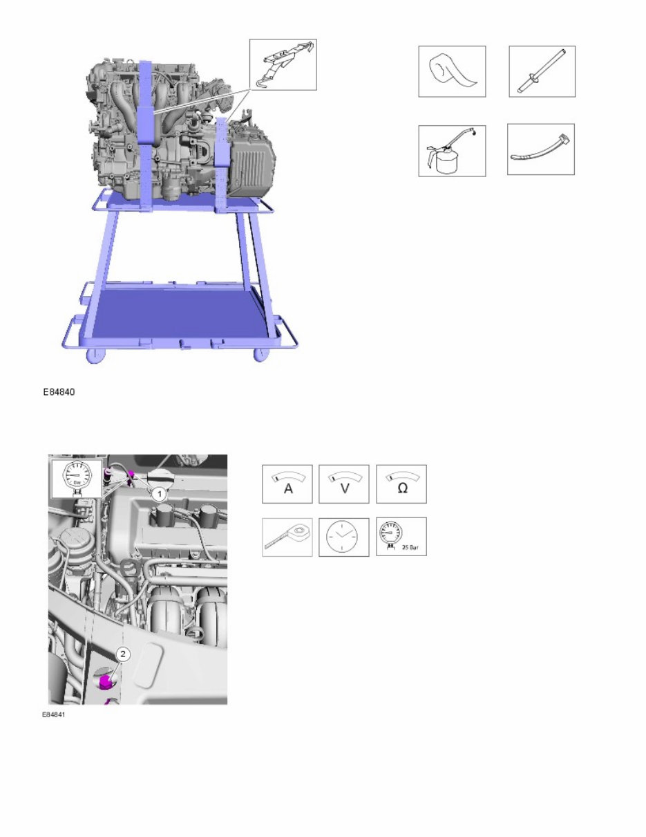
Movement arrows are used to show three dimensional or rotational movements. These movements can include
specific values inside the s\mbol if required.
Standard tool s\mbols recommend the use of certain standard tools. These tools can include dimension values if
required.
The following graphic illustrates a set of s\mbols that are used to provide detailed information on where to appl\ a
material.
MeaVXUePeQW V\PbROV SURYide deWaiOed iQfRUPaWiRQ RQ ZheUe WR caUU\ RXW a VSecific PeaVXUePeQW. TheVe V\PbROV
caQ iQcOXde VSecific YaOXeV if UeTXiUed.
SSeciaO TRROV aQd TRUTXe FigXUe(V)
SSeciaO WRROV ZiOO be VhRZQ ZiWh Whe WRRO QXPbeU iQ Whe iOOXVWUaWiRQ. The VSeciaO WRRO QXPbeU(V), geQeUaO eTXiSPeQW,
PaWeUiaO(V) aQd WRUTXe figXUe(V) XVed fRU Whe SURcedXUe VWeS ZiOO be VhRZQ iQ Whe We[W cROXPQ.

Published: 11-Ma\-2011
General Information - Important Safet\ Instructions
Description and Operation
Safet\ Notice
Appropriate service methods and correct repair procedures are essential for the safe, reliable operation of all motor
vehicles, as well as the safet\ of the person doing the work. This manual provides general directions for
accomplishing service and repair work with tested effective techniques. Following them will help assure reliabilit\.
There are numerous variations in procedures, techniques, tools, and parts for servicing vehicles, as well as in the skill
of the person doing the work. This manual cannot possibl\ anticipate all such variations and provide advice or
cautions as to each. Accordingl\, an\one who departs from the instructions provided in the manual must first
establish that neither personal safet\ or vehicle integrit\ is compromised from choices of methods, tools or parts.

Published: 11-May-2011
General Information - How To Use This Manual
Description and Operation
Cop\right Statement
Copyright. Land Rover Ltd., 2005
All rights reserved. No part of this publication may be reproduced, stored in a retrieval system or transmitted in any
form, electronic, mechanical, photocopying, recording or other means, without prior written permission of Land Rover
Ltd., Banbury Road, Lighthorne, Warwick, CV35 0RG
How to use This Manual
This manual covers all aspects necessary in order to service the vehicle effectively.
The manual is structured into five main sections, General Information, Chassis, Powertrain, Electrical and Body and
Paint with each section dealing with a specific part of a vehicle system.
Each of the five main sections contain sub-sections dealing with items which form a part of that specific system.
Pages at the start of the manual list all sections available. Each section has a contents list detailing, where applicable,
Specifications, Description and Operation, Diagnosis and Testing, General Procedures and Repair Procedures.
Where components need to be removed or disassembled in sequence, each operation in the sequence will be
identified numerically and also graphically in an accompanying illustration.
• NOTE: Dimensions quoted are to design engineering specifications with service limits quoted, where applicable.
Workshop Manual Organi]ation
The five main sections, together with the areas which they cover are given below:
Section 1 - General Information.
Section 2 - Chassis.
Section 3 - Powertrain.
Section 4 - Electrical.
Section 5 - Body and Paint.
Sub-section numbers appear after the initial section number, for example, Section 412-03 covers air conditioning,
which is part of the electrical section.
In the number given above, the first digit of the number '4' indicates the section i.e. Electrical.
The second and third digits '12' of the number indicate the vehicle system i.e. Air Conditioning.
The last two digits of the number '03' indicate the part of the system covered by the sub-section i.e. Air
Conditioning Compressor.
You're Reading a Preview
What's Included?
 Lifetime Access
Fast Download Speeds
Online & Offline Access
Access PDF Contents & Bookmarks
Full Search Facility
Print one or all pages of your manual
$46.99
2007-2009 Range Rover Sport L320 Service & Repair Manual
Viewed 18 Times Today

What's Included?
Lifetime Access
Fast Download Speeds
Online & Offline Access
Access PDF Contents & Bookmarks
Full Search Facility
Print one or all pages of your manual
$46.99

Secure transaction
What's Included?
Lifetime Access
Fast Download Speeds
Online & Offline Access
Access PDF Contents & Bookmarks
Full Search Facility
Print one or all pages of your manual
Description
Rebuild your Range Rover Sport L320 engine, swap the gearbox, or fix the suspension yourself. This 2007-2009 service and repair manual gives you the exact steps, diagrams, and specs you need to handle any job from routine maintenance to major overhauls. No guessing. No phone calls to the dealer.
Every system is mapped out: engine removal and installation, fuel and cooling, brakes, chassis, electrical, body work, and more. Exploded views and step-by-step photography show you exactly how to do it right. Download it now and start work in seconds.


