Land Rover Range Rover Classic 1990-1995 Service Manual
What's Included?
Lifetime Access
Fast Download Speeds
Offline Viewing
Access Contents & Bookmarks
Full Search Facility
Print one or all pages of your manual
;;;f; 1987 CHASSIS AND BODY ‘% BODY REPAIRS, GENERAL INFORMATION Welding The Range Rover body consists of a steel frame to which alloy outer panels are attached. The cowl panel, front fenders, side door outer panels, body side outer panels and roof are made from a special light magnesium-aluminium alloy. The manufacture of body panels from aluminium has two distinct advantages, the first of which is a much better resistance to corrosion, the second being a decrease in the gross vehicle weight. Aluminium panels can be effectively repaired using the ‘Argon Arc ’ process of welding, because the afore mentioned is a specialist operation it is necessary that only a skilled operator or specialist body shop undertake such repairs. .: Under certain conditions it may’ not be practical to repair an exterior damaged panel, if this is the case, then panels can be easily removed and replaced with new ones (refer to the appropriate part of the Body section for panel removal and refit). Panel beating .T.. 1. Aluminium alloy panels can be beaten out after accidental damage in the same way as sheet steel. However, under protracted hammering the material will harden, and then it must be annealed to prevent the possibility of cracking. This is quite easily done by the application of heat, followed by slow air-cooling, but as the melting point is low, heat must be applied slowly and carefully. CAUTION: Before applying heat to any panel ensure that the panel is clean and free from underseal and that the area to be worked on is well clear of any combustible materials. Ensure that all necessary precautions are taken against fire. IF HEAT IS TO BE APPLIED TO THE REAR RIGHT HAND FENDER, THE FENDER MUST FIRST BE REMOVED AS A FUEL EXPANSION TANK IS LOCATED BETWEEN THE FENDER AND INNER BODY SIDE. CAUTION: The battery ground lead MUST be disconnected before commencing welding. IF WELDING IS TO BE CARRIED OUT ON THE REAR RIGHT HAND FENDER, THE FENDER MUST BE REMOVED, AS A FUEL EXPANSION TANK IS LOCATED BETWEEN THE FENDER AND INNER BODY SIDE. 1. Clean off all grease and paint, dry thoroughly and then clean the edges to be welded, and an area at least half an inch on either side of the weld, with a stiff wire scratch brush or wire wool. Cleanliness is essential. Also clean the welding rod or strip with steel wool. 2. It is strongly recommended that a few welds are made on scrap metal before the actual repair is undertaken if the operator is not already experienced in welding aluminium and its alloys. 3. Use only 5 per cent magnesium aluminium welding rod (5 Mg/A). Welding tears and patching 1. If a tear extends to the edge of a panel, start the weld from the end away from the edge and also at this point drill a small hole to prevent the crack spreading, then work towards the edge. 2. When welding a long tear, or making a long welded joint, tack the edges to be welded at intervals of from 2 in to 4 in (50 to 100mm) with spots. This is done by melting the metal at the starting end and fusing into it a small amount of the filler rod, repeating the process at the suggested intervals. After this, weld continuously along the joint from right to left, increasing the speed of the weld as the material heats up. 3. When patching, cut the patch to the correct shape for the hole to be filled, but of such sizes as to leave a gap of l/32 in (0.80mm) between it and the panel, and then weld as described above. Never apply an ‘overlay’ patch. 1 .‘,
76 ‘CHASSIS AND BODY 1987 RANGE ROVER c . Spot welding . 1. spot welding is mainly used in the manufacture of the Range-Rover inner steel body frame and exterior magnesium-aluminium alloy panels, and is a process which can be carried out satisfactorily by the use of the proper apparatus in a specialist body shop. Aluminium and its alloys are very good conductors of heat and electricity, and thus it is most important to maintain the right conditions for successful spot welding. The correct current density must be maintained, and so must the ‘dwell’ of the electrodes. Special spot welding machines have been developed, but they are expensive, and though the actual work can be carried out by comparatively unskilled labour, supervision and machine maintenance must be in the hands of properly qualified persons. Riveting 1. Where both sides of the metal are accessible and it is possible to use an anvil or ‘dolly’ solid aluminium rivets may be used, with a suitable punch or ‘pop’ to ensure clean rounded head on the work. For riveting blind holes, ‘pop-rivets’ must be used. These are inserted and closed by special ‘Lazy-Tong’ ‘pop-rivet’ pliers. 2 PAINTWORK General Information Before undertaking any paintwork process on the exterior body of Range Rover, firstly ascertain which is the best method of repair either by panel repair or replacement. The initial preparation of a panel is very important to ensure that when finished it is of a standard that meets and matches existing bodywork. Panels must be thoroughly degreased with Berger Preclean 802.0516 or a suitable equivalent, any unsound paint to be stripped using Berger Double strength Meltic 301.8051. Always refer to the paint manufacturers instructions. Paintwork processes should be performed by a specialist bodyshop where paint spraying can be undertaken in a controlled environment whereby temperatures are kept constant and the atmosphere dust free. The flow chart on the following page gives a guide to preparing and painting a panel. Wherever possible refer to the Berger Vehicle Refinishes Product Data and Application Sheets for further information. j
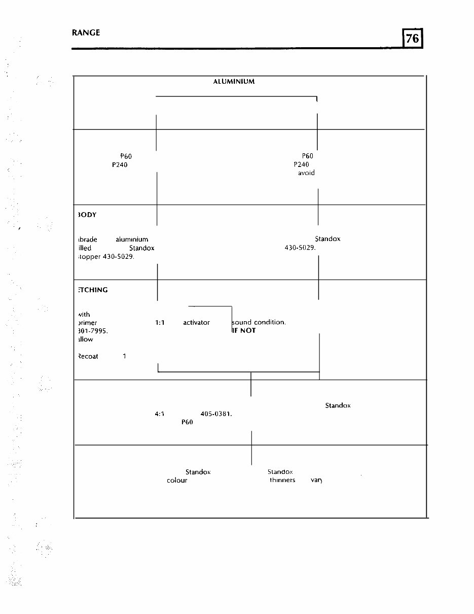
RANGE 1987 ROVER CHASSIS AND BODY SUBSTRATE ALUMINIUM PANELS I I I PANEL REPAIR REPLACEMENT PANEL ‘REPARATION Vet for using P60 Grade paper or dry and using P240 grit discs. Wet flat using P60 Grade paper or dry sand using P240 grit discs. Care must be taken to avord cutting through to bare aluminium. lODY FILLING f filling is required, thoroughly lbrade bare alumrnium area to be illed and apply Standox Polyester Jopper 430-5029. If filling is required, fill small indentations with Standox Polyster stopper 430-5029. iTCHlNG itch the bare aluminium and filler This process is not required if the with auto-speed self etch original electrocoat primer is in lrimer 414-1171, mixed 1:l with actrvator 301-7995. Apply one coat and -1 ;;;zzondition. allow to dry for approximately 20 ninutes. Zecoat within 1 hour. 1 ‘RIMING To obtain maximum adhesion and excellent build, apply Standox 2K 4:l full primer 405-0381. Coats of 30-40 microns can be wet flatted with P60 grade paper after 45 minutes at 20°C. COLOUR COATING Apply either Standox 2K Standocryl or Standox Metallic Basislack ,, to the colour required. Hardeners and thrnners will var) depending upon system employed, conditions available, temperature and size of vehicle etc. Refer to paint manufacturers Technical Information Sheet for correct selection. REVISED: MARCH 90
: .I.> .I . . RANGE CHASSIS AND BODY 1987-90 ROVER REVISED: APR. 87
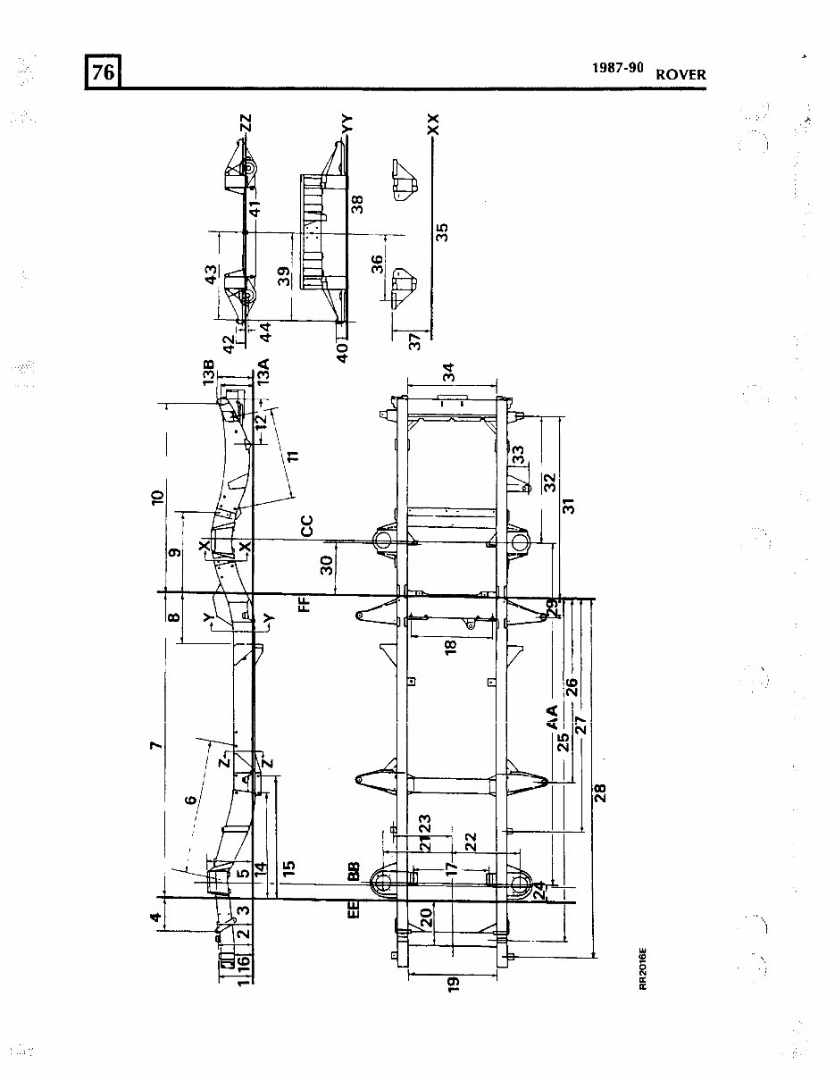
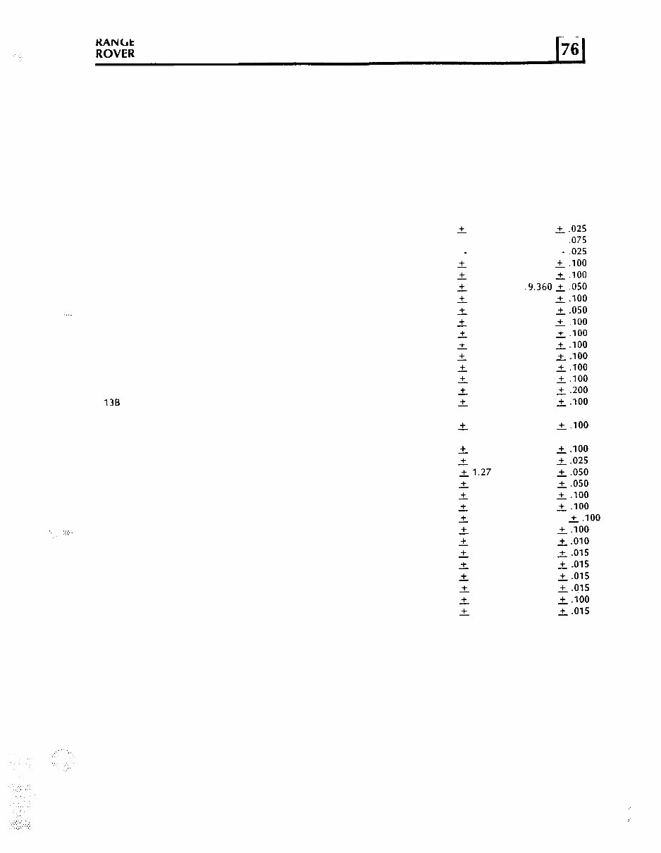
. . . . ‘. :.:.:.. .. ;“o”;; 1987-90 CHASSIS AND BODY CHASSIS FRAME Alignment check AA BB cc DD EE FF 1 2 3 4 5 6 7 8 9 10 11 12 13A 138 14 15 16 17 18 19 20 21 22 23 24 25 26 27 28 29 30 31 Diagram reference millimetres inches Wheelbase-Reference dimension Centre line of front axle Centre line of rear axle Frame datum line Side member datum line Datum line (with mounting washers) (without washers) Reference dimension To face of boss Frame datum to underside of cross-member Check figure 2540.00 100.000 254.00 + 0.63 10.000 + ,025 263.525 + 1.91 10.375 + ,075 - 0.63 - ,025 261.11 2 2.54 10.180 + .I00 266.70 + 2.54 10.500 2.100 237.74 4 1.27 .9.360 + ,050 327.81 f- 2.54 12.906 -f .I00 979.93 + 1.27 38.580 2.050 2244.72 + 2.54 88.375 + .I00 356.74 + 2.54 14.045 +.100 605.15 + 2.54 23.825 +.I00 1405.38 + 2.54 55.330 +-loo 694.44 + 2.54 27.340 +.I00 338.83 + 2.54 13.340 +.100 222.25 2 5.08 8.750 2.200 240.54 + 2.54 9.470 L.100 794.91 31.296 935.43 L 2.54 36.828 +.100 150.79 5.937 535.94 + 2.54 21.100 ~.I00 590.55 + 0.64 23.250 2.025 630.93 ~1.27 24.840 2.050 344.17 + 1.27 13.550 +.050 485.77 f 2.54 19.125 + .I00 485.77 + 2.54 19.125 + .I00 414.32 + 2.54 16.312 +.I00 . 129.03 + 2.54 5.080 +.I00 2544.44 + 0.25 100.175 2.010 1355.34 + 0.38 53.360 2.015 1722.04 + 0.38 67.797 2.015 2663.44 + 0.38 104.860 +.015 144.09 2 0.38 5.673 +.QlS 400.48 fL 2.54 15.767 +.lOO 1333.88 + 0.38 52.515 2.015 Continued 5 " :
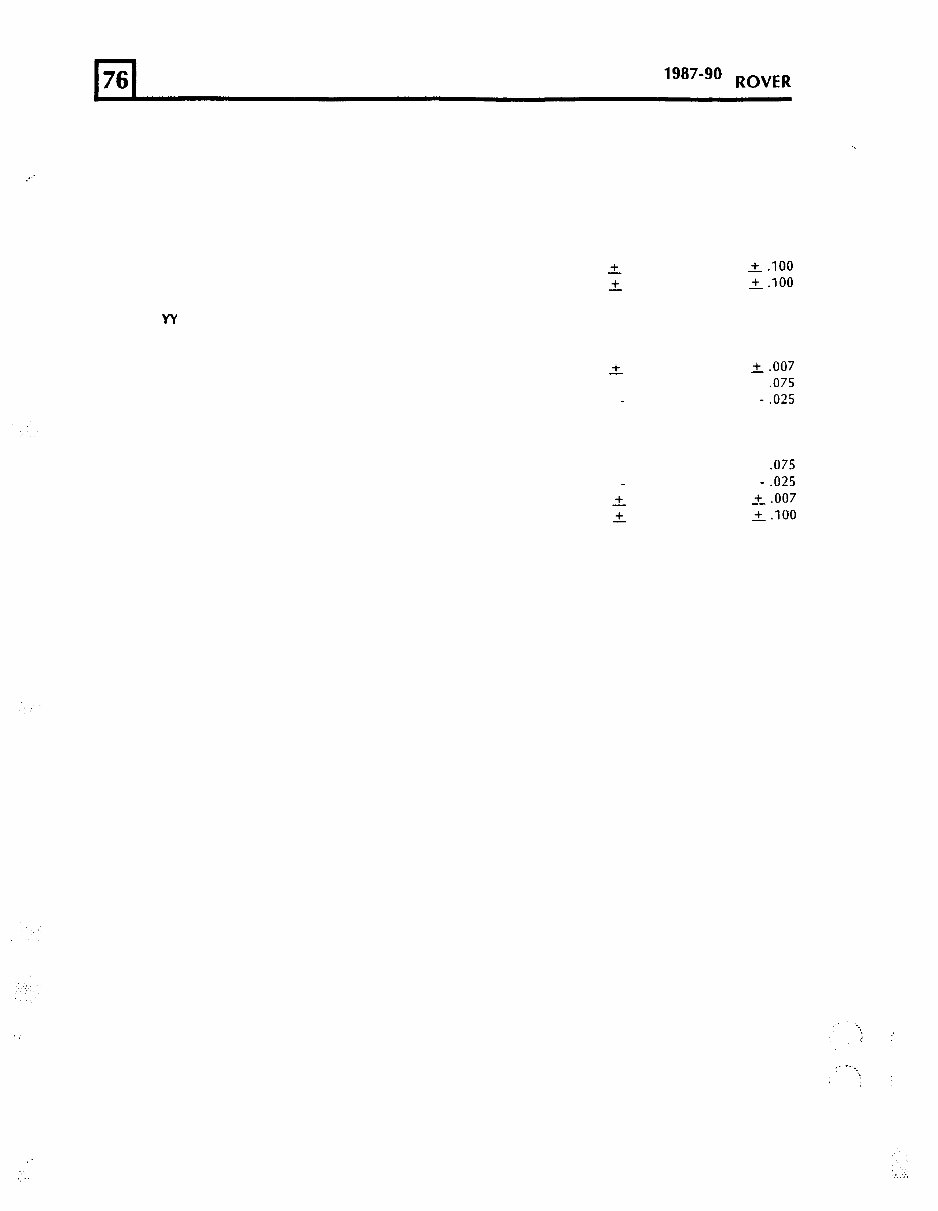
RANGE CHASSIS AND BODY 1987-90 ROVER .c,. ‘.’ 32 Reference dimension 33 Reference dimension 34 Reference dimension SECTION XX 35 Frame datum line DD 36 37 SECTION W 38 Frame datum line DD 39 40 SECTION ZZ 41 Frame datum line DD 42 43 44 millimetres 925.49 36.437 . .. 147.62 5.812 635.00 25.000 488.95 r. 2.54 295.27 2 2.54 660.40 + 0.17 MO.95 + 1.91 - 0.63 80.95 + 1.91 - 0.63 660.4 + 0.17 9.525 + 2.54 inches 19.250 + .lOO 11.625 2.100 26.000 L.007 3.187 + .075 -.025 3.187 + .075 -.025 26.000 _+_.007 0.375 &.I00 : ,:_.
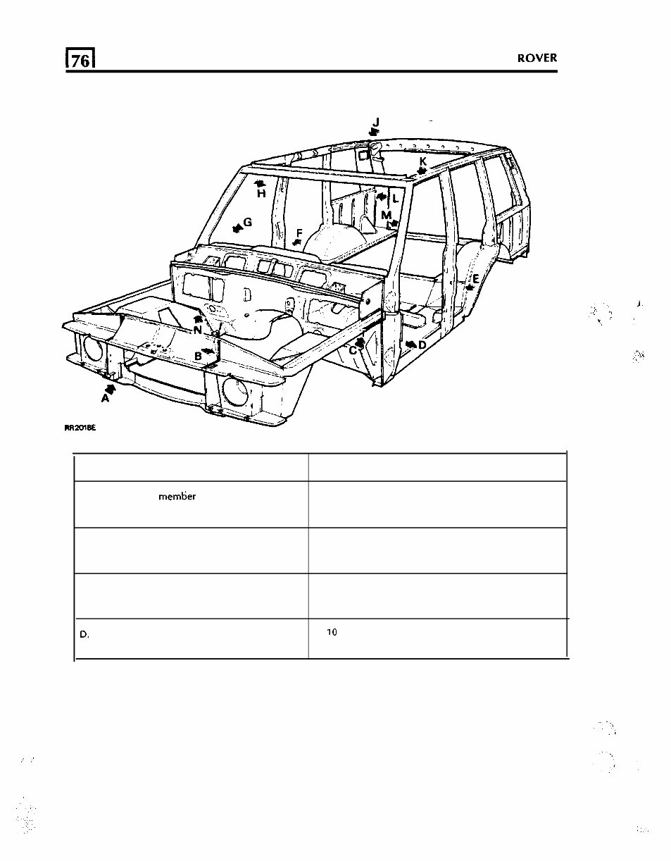
,. .’ CHASSIS AND BODY (76 1 BODY Introduction: The information which follows is concerned solely with the ‘Monocoque’ assembly of the inner body shell on Range Rover models. Body repairs often require the removal of mechanical and electrical units and associated wiring. Where necessary, reference should be made to the relevant section of the Repair Manual for removal and refitting instructions. The inner body shell is of ‘Monocoque’ construction and to gain access to the repair area, it may be necessary to remove exterior body panels, all exterior body panels are bolted to the inner body shell to facilitate easier panel removal and replacement or repair. It is expected that a repairer will select the best and most economic repair method possible, making use of the facilities available. The instructions given are intended to assist a skilled body repairer by expanding approved procedures for panel replacement with the objective of restoring the car to a safe running condition and effecting a repair which is visually acceptable. WELDING The following charts and illustrations show the locations and types of weld for securing the body side assembly, tailgate frame assembly and the front valance and wheel arch assembly. Before undertaking any spot weld joints to the inner body, it is advisable to make a test joint using offcuts of the damaged components, and to use this test piece to perform a weld integrity test. Spot welding is satisfactory if the joints do not pull apart. If the weld pulls a hole or tears the metal the weld is satisfactory. It is defective if the weld joint pulls apart or if there are signs of burning, porosity or cracking evident. PREPARATION Thoroughly clean all areas to be welded, remove any sealants and corrosion protectives from around original panels. Align and clamp all new panels in position and check relationship to one another. Continued 7
l-l 76 CHASSIS AND BODY RANGE 1987-90 ROVER INNER BODY SHELL ASSEMBLY LOCATION FACTORY JOINT (minimum number of spot welds quoted) A. Front cross member to valance and wheel arch assembly 6 spot welds, 20mm pitch B. Hood locking platform to valance and wheel arch assembly 10 spot welds, 25mm pitch C. Valance and wheel arch assembly to dash and tunnel assembly 16 spot welds, 25mm pitch 0. Body side complete to dash IO spot welds, 65mm pitch and tunnel assembly
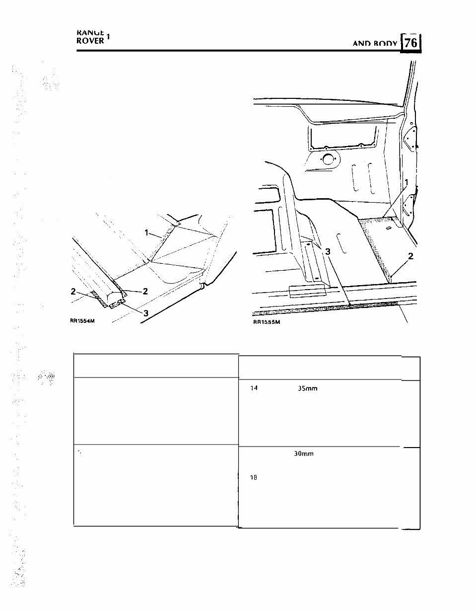
R”o”v‘;l: 7 987-90 CHASSIS ANn Rnnv hiI ./.: :. . :.::: 1.. ., . . . . . ...* .,:. : .; LOCATION E LOCATION E. 1. Body side complete to heelboard panel assembly. 2. Body side complete to dash and tunnel assembly complete. 3. Body side complete to dash and tunnel assembly -. I. Body side complete to dash and tunnel assembly complete 2. Body side complete to dash and tunnel assembly complete 3. Body side complete to dash and tunnel assembly complete LOCATION F FACTORY JOINT (minimum number of spot welds quoted) 14 spot welds, 35mm pitch 10 spot welds, 25mm pitch 3 spot welds, 30mm pitch 7 spot welds, 30mm pitch 18 spot welds, 40mm pitch 30 spot welds, 34mm pitch Continued 9
.I 76 CHASSIS AND BODY RANGE 1987-90 ROVER LOCATION C LOCATION H LOCATION FACTORY JOINT (minimum weld requirement quoted) G. 1. Reinforcement plate to dash and tunnel assembly CO, weld, 2 places 75mm long each weld and body side assembly complete H. 1. Body side complete to roof header panel assembly (internal joint) 3 spot welds, 15mm pitch 2. Body side complete to roof header panel assembly (internal joint) 3 spot welds, 15mm pitch ;:
This is the Land Rover Range Rover Classic 1990 1991 1992 1993 1994 1995 Service Repair Workshop Manual. It contains comprehensive service and repair instructions used by mechanics worldwide.
Key topics covered include:
General Information
Engine Mechanical System
Engine Electrical System
Emission Control System
Fuel System
Clutch System
Manual Transaxle System
Automatic Transaxle System
Driveshaft and Axle
Suspension System
Steering System
Restraint
Brake System
Body (Interior and Exterior)
Body Electrical System
Heating, Ventilation, Air Conditioning
This manual is suitable for both professional mechanics and DIY enthusiasts. It provides the same specifications and procedures available to authorized dealer service departments. The clear and concise text, combined with illustrations, enables anyone with basic mechanical knowledge to safely and easily service and repair their vehicle.
Written by the manufacturers, this manual can assist with any repairs needed. It is not generic repair information; it is vehicle specific and used by technicians at dealerships to maintain, service, diagnose, and repair vehicles.
The manual is available in PDF format, compatible with all versions of Windows and Mac. It is printable and includes pictures and easy-to-follow directions on required tools and repair procedures.
By using this manual, individuals can save a significant amount on repair bills and be better prepared for necessary maintenance. It covers a wide range of systems and components, making it a valuable resource for various vehicle maintenance needs.
Recently Viewed
5,521,897Happy Clients
2,594,462eManuals
1,120,453Trusted Sellers
15Years in Business
Price:
Actual Price:
Land Rover Range Rover Classic 1990-1995 Service Manual