2007-2011 Land Rover Freelander 2 Service & Repair Manual
What's Included?
Lifetime Access
Fast Download Speeds
Offline Viewing
Access Contents & Bookmarks
Full Search Facility
Print one or all pages of your manual
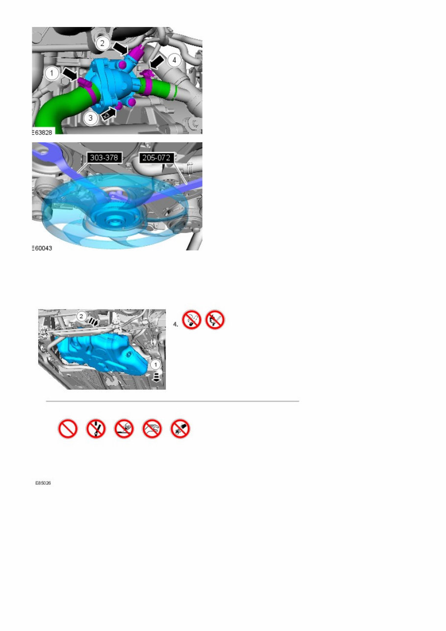
Published: 11-May-2011 General Information - About This Manual Description and Operation Introduction This manual has been written in a format that is designed to meet the needs of technicians worldwide. The objective is to use common formats and include similar content in each manual. This manual provides general descriptions for accomplishing diagnosis and testing, service and repair work with tested and effective techniques. Following them will help to ensure reliability. Important Safety Instructions Appropriate service methods and correct repair procedures are essential for the safe, reliable operation of all motor vehicles as well as the personal safety of the individual carrying out the work. Anyone who departs from the instructions provided in this manual must first establish that personal safety or vehicle integrity is not compromised by the choice of method, tools or components. Warnings, Cautions and Notes in This Manual WARNING: Warnings are used to indicate that failure to follow a procedure correctly may result in personal injury. CAUTION: Cautions are used to indicate that failure to follow a procedure correctly may result in damage to the vehicle or equipment being used. • NOTE: Notes are used to provide additional essential information required to carry out a complete and satisfactory repair. Generic warnings or cautions are in their relevant description and operation procedure within section 100-00. If the generic warnings or cautions are required for a procedure, there will be a referral to the appropriate description and operation procedure. If a warning, caution or note only applies to one step, it is placed at the beginning of the specific step. Trustmark Authoring Standards (TAS) Removal and Installation Procedures • NOTE: TAS style procedures can be identified by steps that have no accompanying step text and the magenta color of the electrical connectors and fasteners such as nuts, bolts, clamps or clips. A TAS removal and installation procedure uses a sequence of color illustrations to indicate the order to be followed when removing/disassembling or installing/assembling a component. Many of the TAS procedures will have the installation information within the removal steps. These procedures will have the following note at the beginning of the procedure: • NOTE: Removal steps in this procedure may contain installation details. Items such as O-ring seals, gaskets, seals, self-locking nuts and bolts are to be discarded and new components installed unless otherwise stated within the procedure. Coated nuts or bolts are to be reused, unless damaged or otherwise stated within the procedure. Specification procedures will contain all technical data that are not part of a repair procedure. TAS Graphics Colors used in the graphic are as follows: Blue - Indicates the target item, item to be removed/installed or disassembled/assembled Green and Brown - Indicates a secondary item that needs to be detached, removed/installed or disassembled/assembled prior to the target item Magenta - Indicates electrical connectors and fasteners such as nuts, bolts, clamps or clips Pale Blue - is for the special tool(s) and general equipment. There may be multiple steps assigned to one illustration. Numbered pointers are used to indicate the number of electrical connectors and fasteners such as nuts, bolts, clamps or clips. Items in the illustration can be transparent or use cutouts to show hidden detail(s). http://topix.landrover.jlrext.com/topix/service/procedure/146634/OD... 1 of 7 29/10/2011 14:37
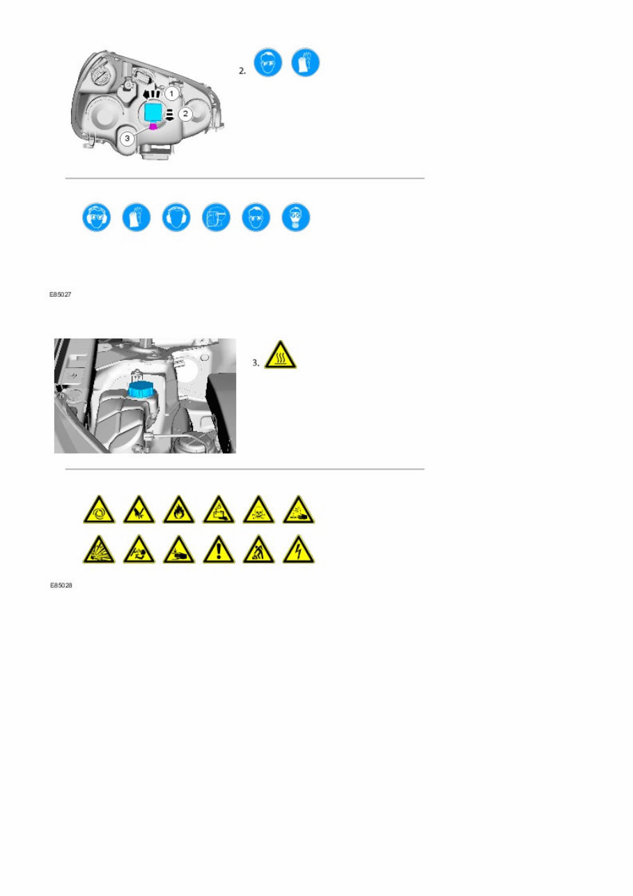
TAS Symbols Symbols are used inside the graphics and in the text area to enhance the information display. The following paragraphs describe the various types and categories of symbols. Prohibition symbols advise on prohibited actions to either avoid damage or health and safety related risks. Health and Safety symbols recommend the use of particular protection equipment to avoid or at least reduce the risk or severity of possible injuries. http://topix.landrover.jlrext.com/topix/service/procedure/146634/OD... 2 of 7 29/10/2011 14:37
Warning symbols are used to indicate potential risks resulting from a certain component or area. Instruction symbols are used to apply sealer, lubricant, weight, tape or cleaning detergent to a component. http://topix.landrover.jlrext.com/topix/service/procedure/146634/OD... 3 of 7 29/10/2011 14:37
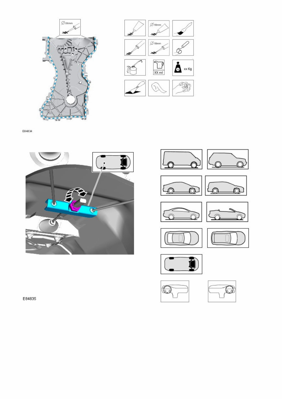
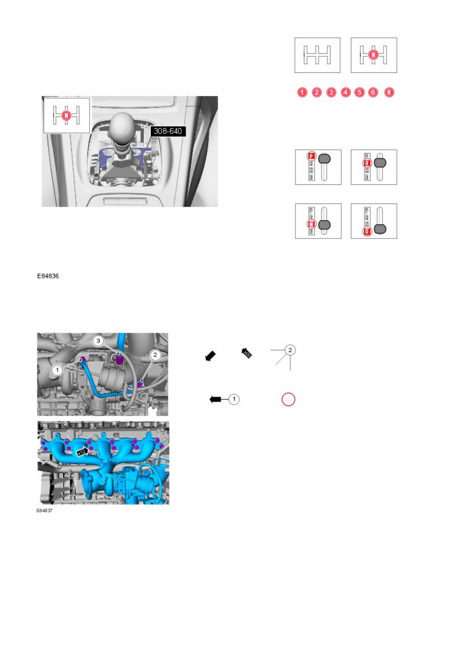
Location symbols are used to show the location of a component or system within the vehicle. Gearshift lever or selector lever position symbols are used to show which gearshift lever or selector lever position is to be set. http://topix.landrover.jlrext.com/topix/service/procedure/146634/OD... 4 of 7 29/10/2011 14:37
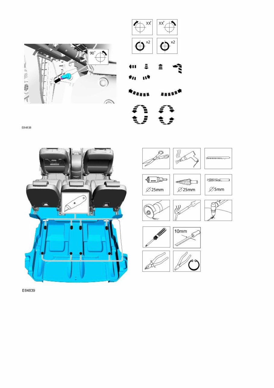
Pointer symbols are used to draw the attention to components and give special instructions such as a required sequence or number of components. The number of components is reflected by the value inside the luty arrow. A sequence number is located inside the circle. Numbers inside circles are also used to allocate special information such as tightening torques or chemicals to a particular component. Movement arrows are used to show three dimensional or rotational movements. These movements can include specific values inside the symbol if required. http://topix.landrover.jlrext.com/topix/service/procedure/146634/OD... 5 of 7 29/10/2011 14:37
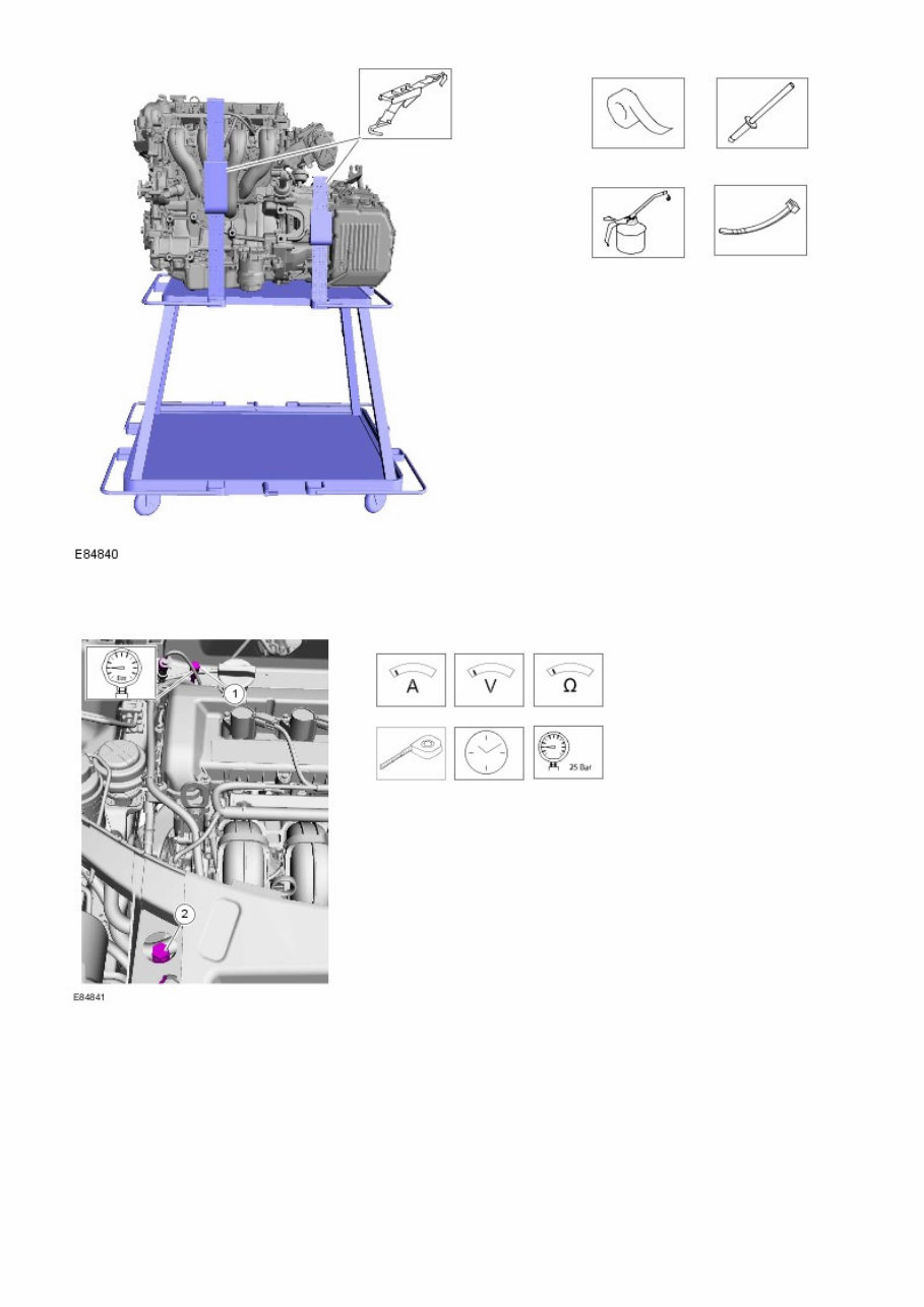
Standard tool symbols recommend the use of certain standard tools. These tools can include dimension values if required. The following graphic illustrates a set of symbols that are used to provide detailed information on where to apply a material. http://topix.landrover.jlrext.com/topix/service/procedure/146634/OD... 6 of 7 29/10/2011 14:37
Measurement symbols provide detailed information on where to carry out a specific measurement. These symbols can include specific values if required. Special Tools and Torque Figure(s) Special tools will be shown with the tool number in the illustration. The special tool number(s), general equipment, material(s) and torque figure(s) used for the procedure step will be shown in the text column. http://topix.landrover.jlrext.com/topix/service/procedure/146634/OD... 7 of 7 29/10/2011 14:37
Get instant access to the Complete 2007-2011 Land Rover Freelander 2 (L359) Service & Repair Manual without any extra fees or expiry dates. This Professional Manual is designed for both professional Mechanics and DIY enthusiasts and covers all repairs, servicing, and troubleshooting procedures specific to the Freelander 2. Detailed photos, diagrams, and exploded views guide you through every repair and maintenance job, ensuring reliable and accurate results.
Features include:
Step-by-step repair instructions for engines, transmissions, brakes, and more
Highly detailed exploded diagrams and illustrations for precise guidance
Comprehensive troubleshooting procedures and servicing techniques
Detailed technical specifications and maintenance schedules specific to the 2007-2011 Land Rover Freelander 2 (L359)
Print out a single page or the entire manual as preferred. Use this Manual on as many computers as required, with no limitations, trial periods, or additional fees. It is fully compatible with both Windows and MAC computers and is available for life use.
For more information, please click on the Button.
Recently Viewed
5,521,897Happy Clients
2,594,462eManuals
1,120,453Trusted Sellers
15Years in Business
Price:
Actual Price:
2007-2011 Land Rover Freelander 2 Service & Repair Manual