

Land Rover DISCOVERY 1996 BODY Repair Manual
What's Included?
Fast Download Speeds
Online & Offline Access
Access PDF Contents & Bookmarks
Full Search Facility
Print one or all pages of your manual
CHASSIS AND BODY
1
REPAIR
FRONT DOOR
Service repair no - 76.28.01
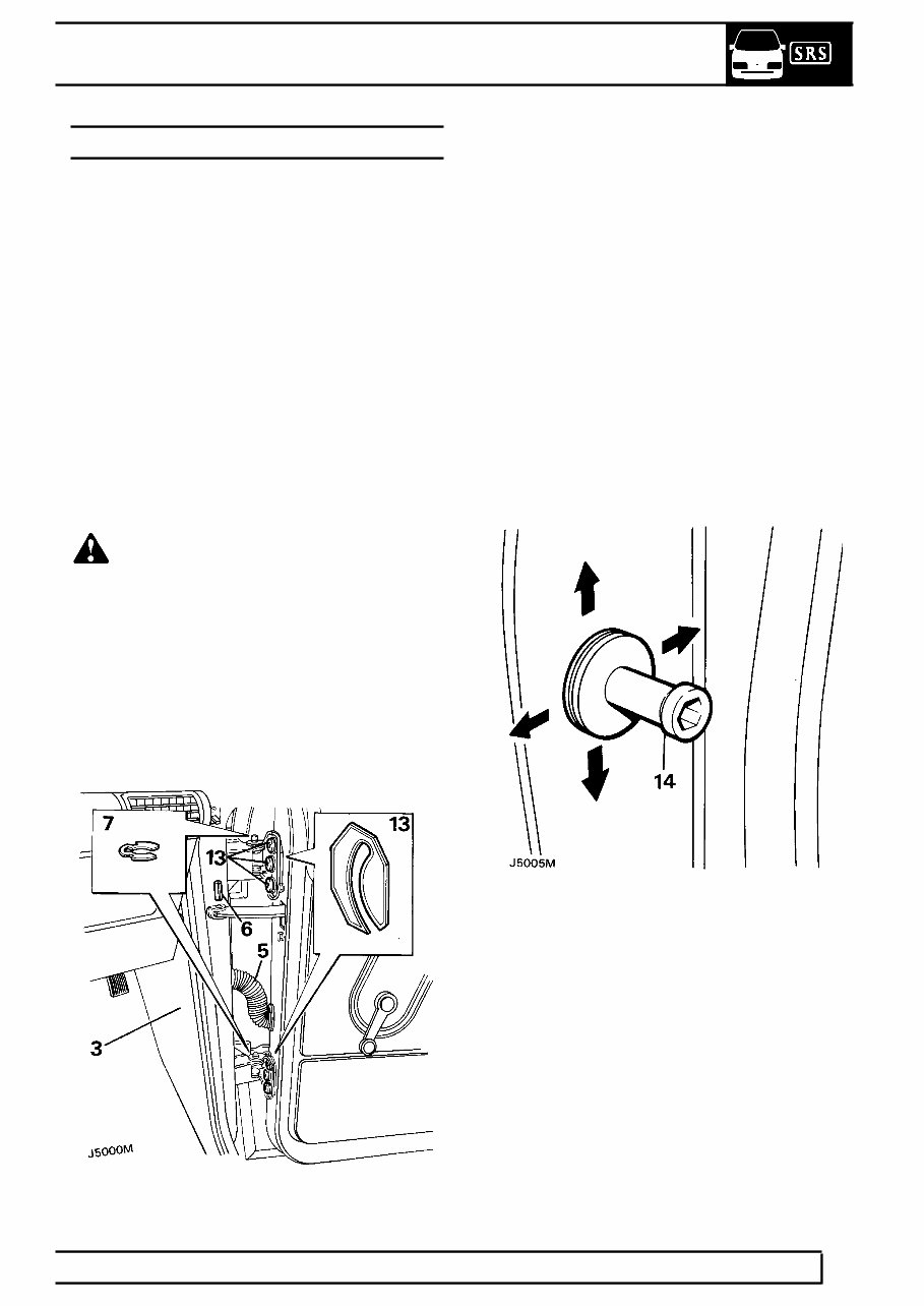
Remove
1. Disconnect battery negative lead.
2. Detach the door seal at the lower section of the
’A’ post.
3. Carefully remove the two retaining buttons from
the trim panel on the side of the footwell and
ease out the panel.
4. Disconnect the three multiplugs connecting the
door harness and speaker leads.
5. Detach the convoluted grommet from the ’A’ post
and withdraw the door harness and speaker
leads.
6. Set the door in the open position without
engaging the check stay; then remove the roll
pin securing the check stay at the ’A’ post.
WARNING: Instruction 7 MUST BE carried
out with assistance.
7. Remove the door hinge ’C’ clips from the hinge
posts and with assistance carefully lift the door
from the vehicle.
Refit
8. Refit the door and secure the hinge posts with
the ’C’ clips.
9. Locate the check stay to the bracket on the ’A’
post and secure with a new roll pin.
10. Feed the door harness and speaker leads
through the aperture in the ’A’ post, fully open
the door and reconnect the multiplugs in the
footwell, take up the slack and refit the
convoluted grommet to the ’A’ post.
11. Refit the footwell side panel.
12. Check the location of the door and the operation
of the door lock. If necessary, adjust the door
and striker.
13. The door can be adjusted up and down or in and
out of the opening by loosening the six screws
securing the hinges to the door, and by the
addition or removal of shims between the hinge
and door.
14. The door lock striker can be adjusted by
loosening the striker and moving it in the
appropriate direction or by adding and removing
spacing washers between the striker and ’B’
post.
cardiagn.com
76
CHASSIS AND BODY
2
REPAIR
FRONT DOOR TRIM PANEL
Service repair no - 76.34.01
Remove
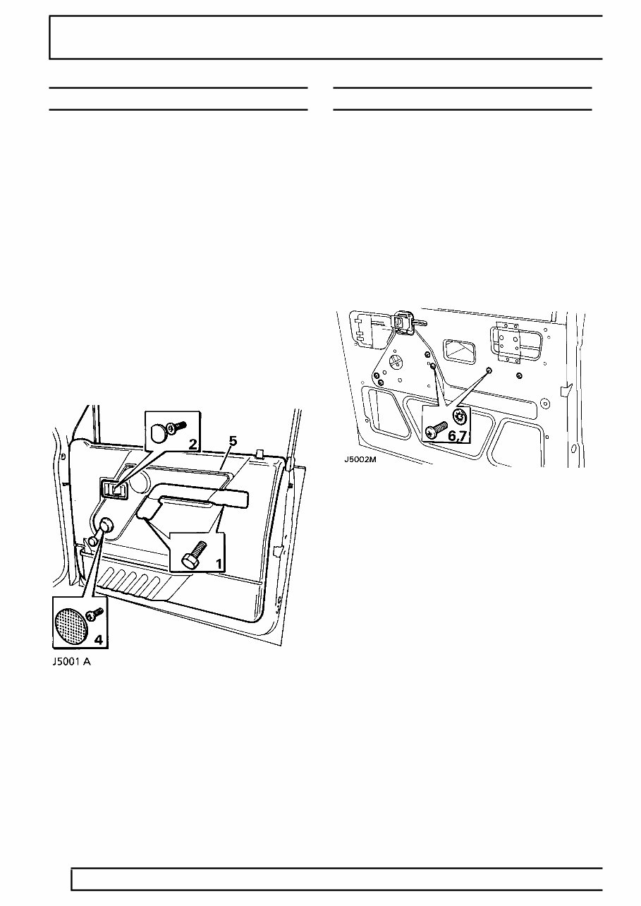
1. Remove the two securing screws and detach the
door pull from its mounting brackets on the inner
door panel.
2. Remove the interior door handle finisher button
to reveal the screw retaining the handle
surround.
3. Remove the screw and detach the handle
surround from the trim panel.
4. Where applicable remove the window winder.
5. Detach the trim panel by inserting a trim panel
removing tool between the trim panel and the
inner door panel, gently prise out the fourteen
plastic securing clips from their respective holes
in the inner door panel.
6. Disconnect the two speaker connections from
inside the door and remove the trim panel
complete with speaker, and door bin.
7. If a new trim panel is to be fitted, remove the
speaker, door bin and remote button finisher
from the existing trim panel and fit them to the
new panel.
Refit
8. Reverse removal procedure.
FRONT DOOR GLASS AND REGULATOR
Service repair no - 76.31.45
Remove
1. Ensure the window is in the fully closed position
and secure with adhesive tape to prevent the
window from dropping down.
2. Disconnect battery negative lead.
3. Remove the door trim panel. See front door
trim panel.
4. Remove the plastic vapour barrier.
5. Where applicable remove the window lift motor.
See ELECTRICAL, Repair, window lift motor
- front.
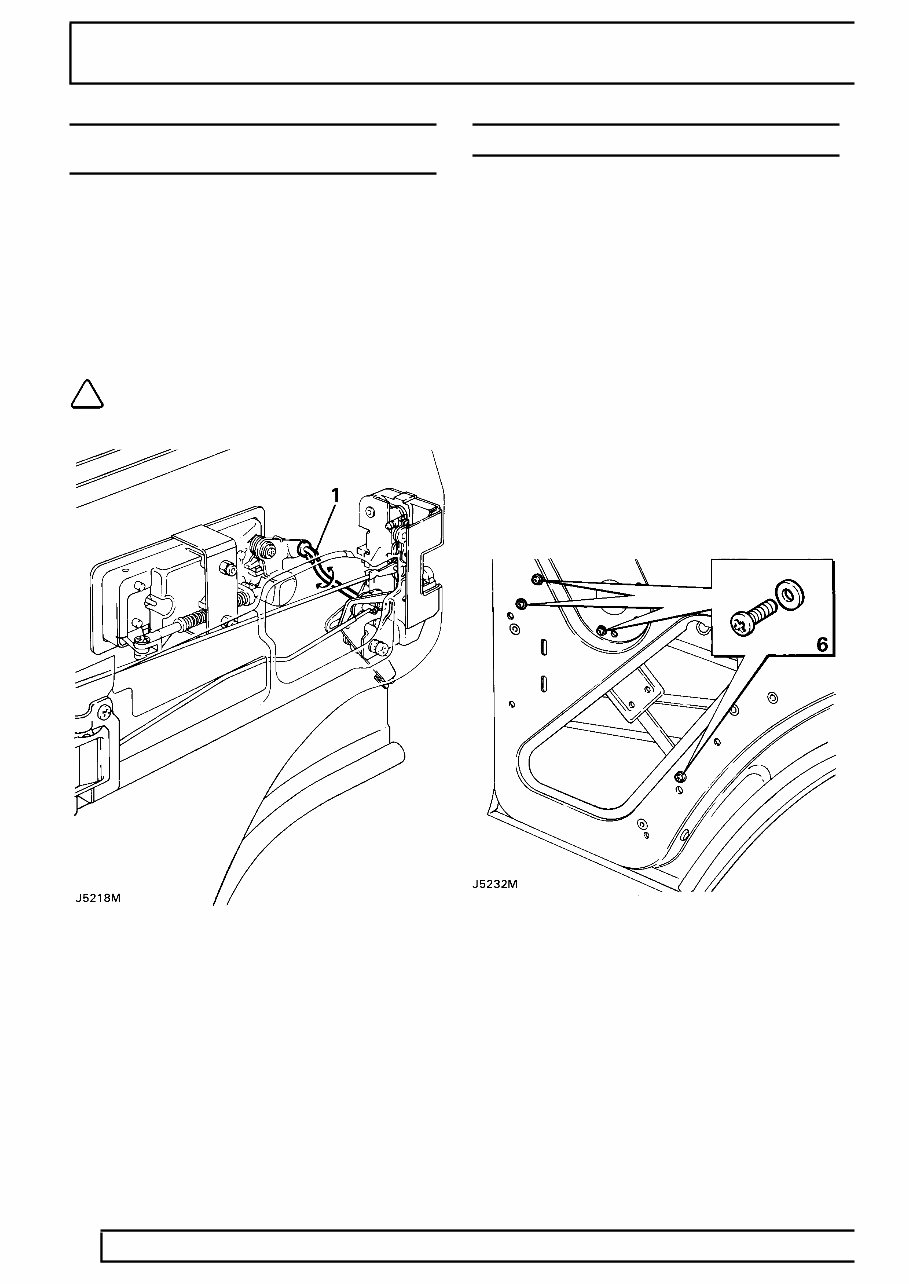
6. Remove the four window regulator retaining
screws and shakeproof washers from the inner
door panel.
7. Remove the two screws and shakeproof
washers retaining the lower window lift channel,
and slide the channel off the stud.
cardiagn.com
CHASSIS AND BODY
3
REPAIR
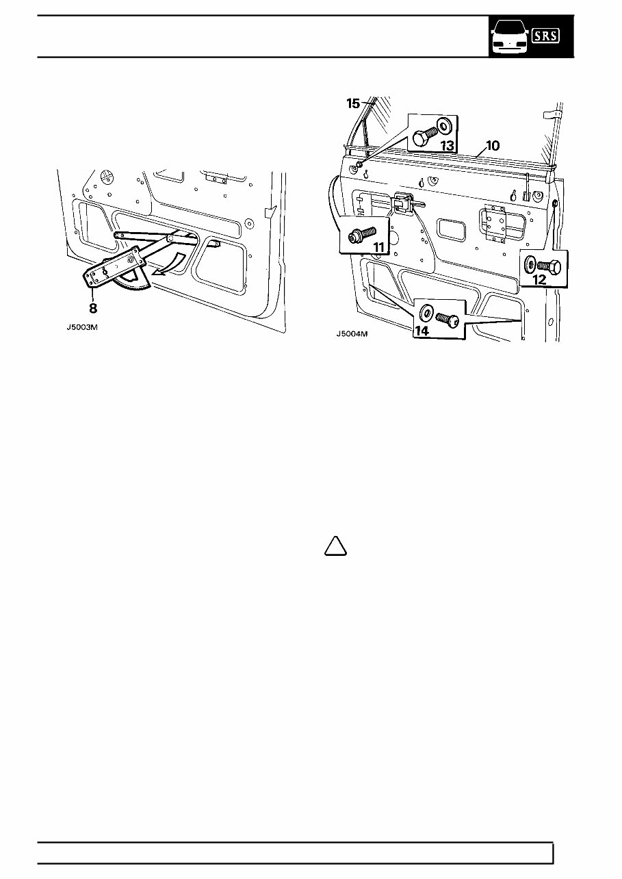
8. Disengage the lifting arm stud from the upper
lifting channel, manoeuvre the window regulator
and remove it from the lower centre opening in
the inner door panel.
9. Remove the exterior driving mirror. See
ELECTRICAL, Repair, exterior driving
mirrors.
10. Remove the waist rail seal from the top of the
door panel.
11. Remove the ’Torx’ bolt from the hinge face of the
door which secures the front of the door frame.
12. Remove the bolt and plain washer from the
opening edge of the door which secures the rear
of the door frame.
13. Remove the bolt and plain washer from the
recessed hole in the front of the inner door panel
under the exterior driving mirror mounting plate.
14. Remove the screws and plain washers, from
inside the door, securing the bottom of the front
and rear glass channels.
15. Lift the door glass frame complete with glass out
of the door panel and remove to a suitable
bench.
16. Remove the adhesive tape securing the glass to
the door frame.
17. Slide the glass out of the door frame channel.
Refit
NOTE: When refitting the door glass
frame, ensure it is repositioned to suit the
door opening before fully tightening the
door frame securing bolts.
18. Reverse removal procedure.
cardiagn.com
76
CHASSIS AND BODY
4
REPAIR
FRONT DOOR LOCK, OUTSIDE AND INSIDE
DOOR RELEASE HANDLES
Service repair no - 76.37.12/31
Remove
1. Disconnect battery negative lead.
2. Remove the door trim panel. See front door
trim panel.
3. Remove the door glass and regulator. See
front door glass and regulator.
4. Where applicable remove the door actuator unit.
See ELECTRICAL, Repair, front door
actuator unit.
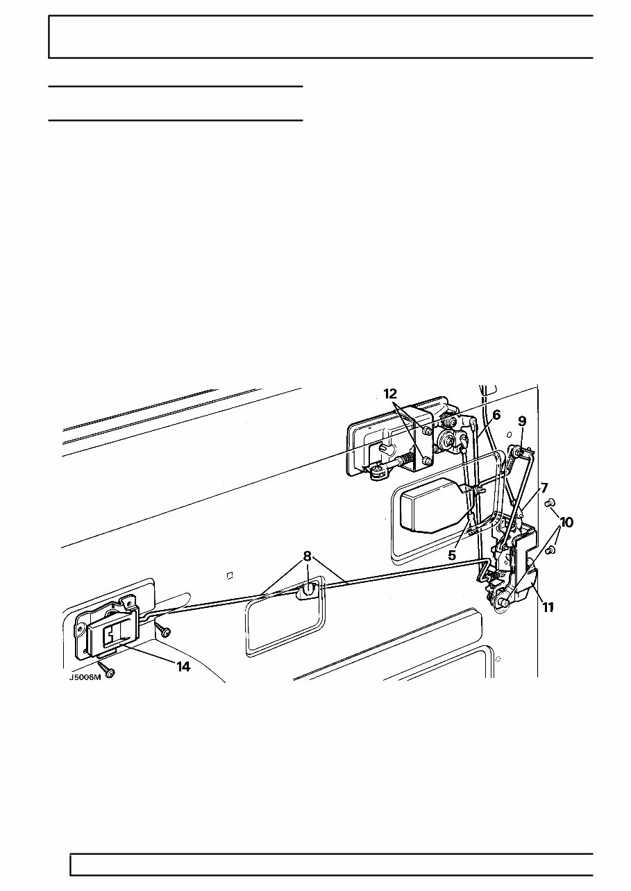
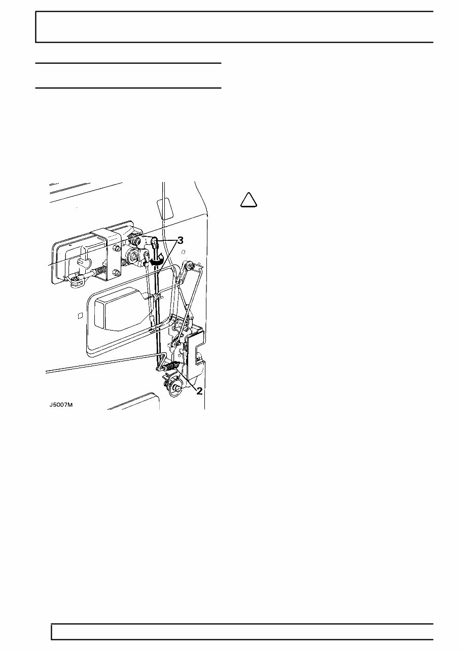
5. Disconnect the lock barrel control rod from the
lock by releasing the metal clip at the bottom of
the rod.
6. Disconnect the control rod from the outside door
release handle by pulling it out of the plastic
ferrule.
7. Disconnect the remote button control rod from
the lock by releasing the metal clip at the bottom
of the rod and withdraw the rod from the door.
8. Disconnect the control rod connector between
the inside door release handle and the door lock
by releasing the metal clip and pulling one of the
control rods out of the plastic connecting block.
This is accessible through the small centre
cut-out in the door panel. The control rod also
passes through a guide bracket in the inside of
the inner door panel.
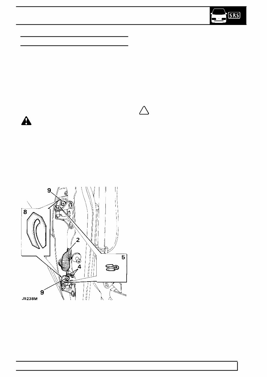
9. From inside the door panel push out the small
pin that secures the quadrant to the inner door
panel. Push the quadrant out of the panel.
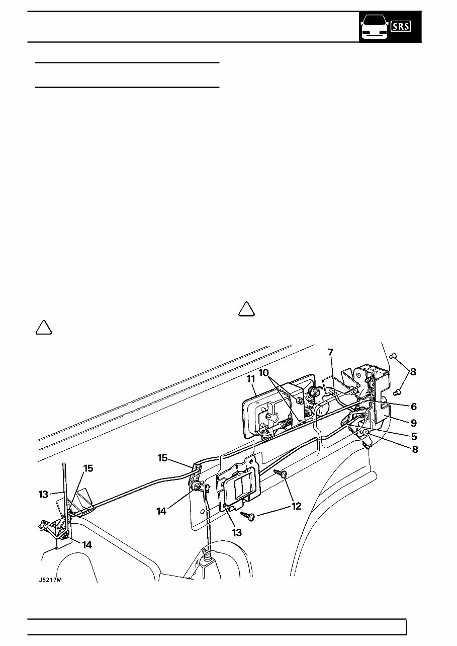
10. Release the door lock by removing the two
counter-sunk screws from the door edge and the
single screw and shakeproof washer on the
inner door panel.
cardiagn.com

CHASSIS AND BODY
5
REPAIR
11. Withdraw the lock through the lower rear cut-out
on the inner door panel.
12. Remove the two nuts, shakeproof washers and
retaining bracket securing the outer door release
handle to the outer door panel, accessible
through the upper rear cut-out on the inner door
panel.
13. Carefully detach the door release handle from
the outer panel.
14. Remove the two screws securing the inside door
release handle to the inner panel.
15. Withdraw the handle from its location with the
connecting rod half still attached.
16. Unclip the end of the connecting rod from the
handle.
Refit
17. Reverse removal procedure.
cardiagn.com
76
CHASSIS AND BODY
6
REPAIR
ADJUSTMENT-FRONT DOOR LOCK AND HANDLE
ASSEMBLY
Service repair no - 76.37.47
Inside door release handle to lock
1. Refit the inside door release handle surround
before any adjustment is made, allowing the
handle to be set from the correct operating
position.
2. At the lock end of the interior handle connecting
rod, rotate the spring tensioned nyloc nut
clockwise or counter-clockwise, as necessary to
shorten or extend the operating length of the rod.
Outside door release handle to lock
3. Disconnect the connecting rod from the plastic
ferrule at the rear of the outer door release
handle. Rotate the rod clockwise or
counter-clockwise to shorten or extend the
operating length as necessary.
NOTE: Door release should be effective
before the total handle movement is
exhausted to provide a small overthrow
movement.
cardiagn.com
CHASSIS AND BODY
7
REPAIR
REAR SIDE DOORS
Service repair no - 76.28.02
Remove
1. Disconnect battery negative lead.
2. Detach the convoluted grommet from the ’B’
post.
3. Withdraw the door harness multiplugs from the
’B’ post and disconnect them.
4. Remove the bolts and washers securing the
check strap to the ’B’ post.
WARNING: Instruction 5 MUST BE carried
out with assistance.
5. Remove the door hinge ’C’ clips from the hinge
posts and with assistance carefully lift the door
from the vehicle.
Refit
6. Reverse removal procedure. Fitting new ’C’ clips
if the existing ones are worn or distorted.
7. Check the operation of the door and lock. If
necessary, adjust the door and striker.
Adjust
8. Adjust the door by adding or removing shims
between the hinge and the door to move the
door forward or rearward in the opening.
9. To adjust the door up, down or in and out of the
opening, loosen the screws securing the hinges
to the door, adjust as necessary and retighten
the screws to the correct torque value.
10. Adjustment of the door striker is identical to the
procedure for front doors.
NOTE: If it is necessary to remove the
hinges from the ’B’ post they must be
refitted in exactly the same position, using
an equal thickness of shims to those removed.
cardiagn.com

76
CHASSIS AND BODY
8
REPAIR
REAR SIDE DOOR - TRIM PANEL
Service repair no - 76.34.04
Remove
1. Disconnect battery negative lead.
2. Remove the two securing screws and detach the
door pull from its mounting brackets.
3. Remove the securing screw and detach the
interior door release handle surround.
4. Where applicable remove the window winder or
release electric switch and disconnect.
5. Detach the trim panel by inserting a trim panel
removing tool between the trim panel and the
inner door panel, gently prise out the plastic
securing clips from their respective holes in the
inner panel.
6. Lift the trim panel over the remote button and
clear of the door. Where applicable disconnect
the electrical plug from the window lift switch and
withdraw the panel.
NOTE: With the trim panel removed the
remote button and rod will fall from its
location in the bellcrank. Observe its
correct location and withdraw from the door
panel.
7. If a new trim panel is to be fitted, remove the
window lift switch, door bin and remote button
finisher from the existing trim panel and fit them
to the new panel.
Refit
8. Reverse removal procedure. Ensuring correct
fitment of the sill button operating rod.
cardiagn.com
CHASSIS AND BODY
9
REPAIR
REAR SIDE DOOR LOCK, INSIDE AND OUTSIDE
RELEASE HANDLES
Service repair no - 76.37.13/32
Remove
1. Ensure that the window is in the fully closed
position.
2. Disconnect battery negative lead.
3. Remove the interior trim panel from the door.
See rear side door - trim panel.
4. Remove the plastic vapour barrier sheet.
5. Disconnect the inside release handle control rod
by pulling it from its location in the door lock.
6. Disconnect the sill locking control rod from the
lock by releasing the metal clip.
7. Disconnect the outside release handle control
rod by pulling it out of the plastic ferrule.
8. Remove the two countersunk screws from the
door edge and the single screw and shakeproof
washer from the inner door panel. Retrieve any
spacing washers which may be fitted between
the inner door panel and lock.
9. Withdraw the lock through the upper rear
opening in the inner door panel.
NOTE: If necessary the following items
can be removed.
10. Remove the two nuts, shakeproof washers and
retaining bracket securing the outer release
handle which are accessible through the upper
rear cut-out on the inner door panel.
11. Carefully detach the handle from the outer door
panel.
12. Remove the two screws and plain washers
securing the inside release handle to the inner
door panel and withdraw the handle complete
with connecting rod.
13. Disconnect the sill button connecting rod from
the bellcrank and withdraw the rod complete with
sill button.
Sill locking bellcrank
14. Using a small screwdriver, or length of 3.175 mm
(1/8 in) diameter rod, press the plastic locking
pins through the respective square inserts in the
inner door panel.
15. Release the bellcranks from the inner door panel
and unhook the respective connecting rods.
16. Withdraw the bellcranks from inside the door
panels.
NOTE: When refitting the bellcranks the
locking pins are entered into the square
insert from outside and pressed in flush.
cardiagn.com
76
CHASSIS AND BODY
10
REPAIR
ADJUSTMENT-REAR SIDE DOOR LOCK AND
HANDLE
Service repair no - 76.37.47
Outside door release handle to lock
1. Disconnect the short off-set connecting rod at
the rear of the outer release handle, rotate the
rod clockwise or counter clockwise to shorten or
extend the operating length of the rod as
required.
NOTE: Door release should occur before
the total handle movement is achieved to
provide a small overthrow movement.
REAR SIDE DOOR GLASS AND REGULATOR
Service repair no - 76.31.45
Remove
1. Ensure that the window is in the fully closed
position and secure it with adhesive tape over
the top of the door to prevent the glass from
dropping down.
2. Disconnect battery negative lead.
3. Remove the door trim panel. See rear side
door - trim panel.
4. Remove the plastic vapour barrier.
5. Where applicable remove the door actuator and
window lift motor. See ELECTRICAL, Repair,
window lift motor - rear. See ELECTRICAL,
Repair, rear side door actuator units.
6. Remove the four window regulator securing
screws and shakeproof washers from the inner
door panel.
7. Carefully disengage the lifting arm stud from the
glass lifting channel and remove the window
regulator from the lower opening in the inner
door panel.
8. Remove the waist rail seal from the top of the
door panel.
9. Remove the single bolt, spring and plain
washers from inside the door, securing the
bottom of the short glass run channel.
10. Remove the two bolts, spring and plain washers
from the hinge face of the door.
cardiagn.com
You're Reading a Preview
What's Included?
Fast Download Speeds
Online & Offline Access
Access PDF Contents & Bookmarks
Full Search Facility
Print one or all pages of your manual
$27.99
$36.99
Viewed 48 Times Today


Secure transaction
What's Included?
Fast Download Speeds
Online & Offline Access
Access PDF Contents & Bookmarks
Full Search Facility
Print one or all pages of your manual
$27.99
$36.99
The manual you will receive contains all the necessary instructions for repairing your vehicle from front to back. It is used by professional mechanics and DIY enthusiasts alike, making it a valuable resource for saving money and ensuring your car runs at its best.
Inside, you will find illustrations, diagrams, technical specifications, and step-by-step explanations for various repair procedures. Even with basic mechanical knowledge, you can easily and safely service your car using this manual.
Contents of the Repair Manual:
- Engine Overhaul and Rebuilding
- Troubleshooting and Diagnostics
- Computer Diagnostic Trouble Tree Charts
- Engine Performance
- Front End and Alignment Procedures and Specifications
- Suspension
- Transmission Removal and Installation
- Air Conditioning Service and Capacities
- Transmission In Car Servicing
- Firing Orders - Detailed Specifications Covered
- Timing Belt Service Procedures
- Brake Servicing Procedures
- Complete Torque Specifications
- U-Joint and CV-Joint Service Procedures
- Repair Procedures
- Complete Wiring Diagrams
- Vacuum Diagrams
And much more.


