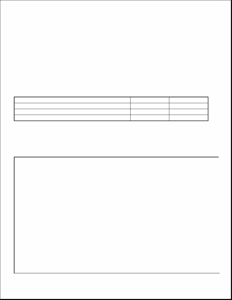
TRANSFER CASE Four-Wheel Drive Systems FOUR-WHEEL DRIVE SYSTEMS SPECIFICATIONS Torque Specifications DESCRIPTION & OPERATION FOUR-WHEEL DRIVE SYSTEMS Transfer Box Component Location NOTE: * New bolts must be fitted. Description Nm lb-ft * Transfer case shift motor Torx bolts 25 18 * Transfer case clutch control solenoid Torx bolts 10 7 * High/Low range sensor Torx bolts 10 7
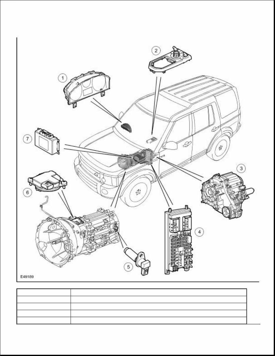
Item Number Description 1 Instrument cluster 2 Range change selection switch 3 Transfer box 4 Central junction box (CJB)
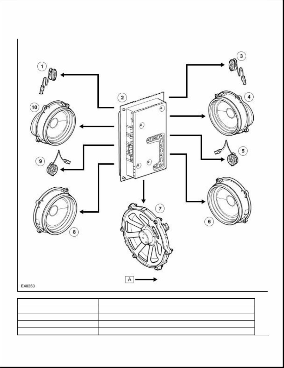
Transfer Box Exploded View 5 Manual transmission output shaft speed sensor 6 Gear position sensor (manual transmission only) 7 Transfer box control module
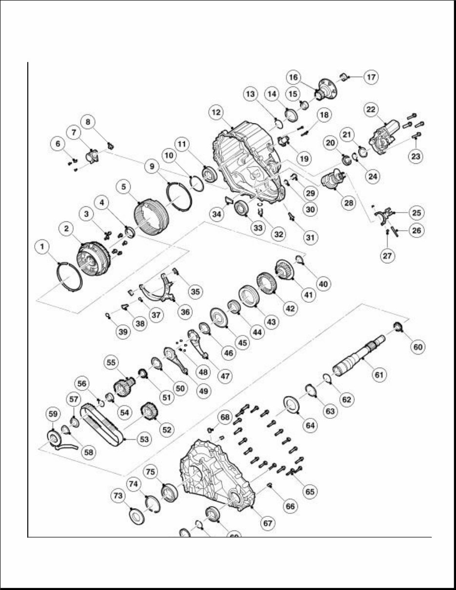
Item Number Description 1 Synchronisation spring 2 Differential assembly 3 Bolt, 6 off 4 Spacer ring 5 Shifting sleeve 6 Bolt, 3 off 7 Solenoid 8 Shifting element 9 Synchronisation spring 10 Circlip 11 Ball bearing 12 Rear housing 13 Circlip 14 Seal ring 15 Needle roller bearing 16 Rear output flange 17 Needle roller bearing 18 Bolt, 2 off 19 Selector fork position sensor 20 Bearing 21 Circlip 22 Transfer box motor assembly 23 Bolt, 4 off 24 Circlip 25 Shifting fork 26 Fork pin 27 Sliding block 28 Actuator assembly 29 Fill plug 30 Seal ring 31 Ball retention 32 Drain plug 33 Seal ring 34 Particle collector magnet 35 Sliding block 36 High/low shifting fork 37 O-ring 38 High/low fork pin 39 Circlip 40 Circlip
GENERAL The DD295 transfer box is a full time, permanent four-wheel-drive unit, with 50/50 torque distribution to the front and rear driveshafts. The unit is manufactured by Magna Steyr Powertrain in Graz, Austria and supports the following features: Clutch hub 42 Clutch friction plate, 10 off 43 Clutch steel plate, 10 off 44 Disc spring, 6 off 45 Clutch piston 46 Axial needle roller bearing 47 Transfer box motor lever assembly 48 Ball, 5 off 49 Transfer box motor lever assembly 50 Axial needle roller bearing 51 Needle roller bearing 52 Front output sprocket 53 Chain 54 Needle roller bearing 55 Sprocket 56 Circlip 57 Thrust washer 58 Spacer ring 59 Oil pump assembly 60 Needle roller bearing 61 Input shaft 62 O-ring 63 Circlip 64 Disc spring, 2 off 65 Bolt, 19 off 66 Dowel pin (2 off) 67 Front housing 68 Breather cartridge 69 Bearing 70 Circlip 71 Seal ring 72 Front output flange 73 Seal ring 74 Circlip 75 Bearing
Permanent four-wheel-drive with a bevel gear centre differential, providing a 50:50 torque split Selectable high and low range for optimum on-road and off-road performance Two-speed, fully synchronized 'shift-on-the-move' system allows the driver to change the range without having to stop the vehicle Electronically controlled multi-plate clutch providing a centre differential lock and torque biasing function to give improved traction performance and vehicle dynamic stability. A strategy, to electronically control the centre differential multi plate clutch assembly, has been developed to provide: A pre-loading function, increasing locking torque with increased driving torque A slip controller to increase locking torque under off-road conditions and decrease locking torque for optimum comfort, e.g. parking. The unit is located under the vehicle and is mounted on the cross-member, behind the transmission. The unit is identical for all engine derivatives. The transfer box receives a torque input from the transmission output shaft, which is passed through the unit to two outputs for the front and rear drive shafts. The input torque is equally distributed via a bevel gear type differential. In order to provide an optimal torque distribution to each wheel in all driving conditions, the unit is equipped with an electronically controlled locking and torque-biasing device. This device detects wheel slip via various vehicle system inputs to the transfer box control module and locks the differential accordingly. The locking torque is applied through a multi-plate clutch assembly. A planetary gear set, located in the differential assembly, allows the driver to select high or low range whilst driving, this is known as 'shift on the move'. When in low range, the planetary gear set provides a ratio of 2.93:1, which gives the vehicle an extremely low crawl speed for off road driving and trailer towing. High range is a direct drive from the transmission output shaft and provides a 1:1 ratio. Both the centre differential locking and biasing and the 'shift on the move' features are actuated via a DC transfer box motor, which is controlled by the transfer box control module, via a Pulse Width Modulation (PWM) signal. Transfer Box - Sectional View
Item Number Description 1 Planetary gear set 2 Rear output flange 3 Centre differential assembly 4 Multi-plate clutch
Transfer Box Power Flow 5 Transfer box motor module 6 Rear housing assembly 7 Front output sprocket 8 Chain drive 9 Front output flange 10 Transfer box motor levers 11 Sprocket 12 Oil pump assembly 13 Input shaft 14 Front housing assembly
If you are in need of a repair manual for your 2011 Land Rover LR4, look no further. This comprehensive manual is designed to assist both professional mechanics and DIY enthusiasts in performing a wide range of repairs and maintenance tasks.
In the past, obtaining service information required purchasing traditional paper manuals at a higher cost. However, this accessible digital format offers a more affordable and convenient alternative.
Whether you are tackling brake repairs, suspension component replacements, engine troubleshooting, or standard maintenance procedures, this manual provides all the necessary guidance.
With this manual, you will have access to detailed service information covering brakes, engine, suspension, steering, drivetrain, electrical systems, heating, air conditioning, and more.
By utilizing this manual, you can save a significant amount of money on vehicle repairs. Professional mechanics often charge high fees for their services, making a DIY approach a cost-effective option.
This 2011 Land Rover LR4 repair manual is compatible with Windows, Mac computers, smartphones, and tablets, ensuring ease of use across various devices.