

1983-1990 Land Rover Defender 110 Service & Repair Manual
What's Included?
Fast Download Speeds
Online & Offline Access
Access PDF Contents & Bookmarks
Full Search Facility
Print one or all pages of your manual
SLRSZ1EìWh.I

TABLE OF' CONTENTS
SECTION
Introduction mI
......................................................................................................
...................................................................................
El
General Specification Data
..........................
Engine Tuning Data.. .I!. .............................................................
.....................................................................................
Torque Wrench Settings.. mb
.................................................................................. m I
General Fitting Instructions
.....................................................
.....................................................................................................
El " 1
Recommended Lubricants, Fluids and Capacities..
Maintenance
El
El
El
Engine .............................................................................................................
,~ Cooling System ..................................................................................................
..................................................................... Fuel System (including Fuel Injection)
...
."
..I
Clutch.. ............................................................................................................ O J
.........................................................................
w
El
w
Manual Gearbox and Transfer Box
Propeller Shafts..
Rear Axle and Final Drive
................................................................................................
....................................................................................
..........................................................................................................
\
Steering..
Suspension ........................................................................................................
Brakes
.............................................................................................................
Electrical ..........................................................................................................
BOOK
2
5
BOOK ONE CONTENTS
05
Page
ENGINE TUNING DATA
Section
Number
ri
- Repairsand replacement parts
- Poisonous substances
-Fuel handling precautions
-Fuel tank draining and repair
J
. . -
- Service tools 5
- Location of vehicle identification numbers
6
06 TORQUE WRENCH SETINGS
El GENERAL SPECIFICATION DATA
- V8 engine data
-2.25 litre petrol engine data
-2.25 litre petrol engine data
- 2.25 litre dicscl cnginc data
- 2.50 litre dicsel engine data
- General data - all models
- Tyrepressures
- Replacemcnt bulbs and units
- Vchiclc wcights
1
3
5
7
9
11
19
19
20
- V8 engine tuning data
- 2.25 litre petrol engine tuning data
- 2.5 litre petrol engine tuning data
- 2.25 and 2.50 litre dicscl engine tuning data
7
:I'.. i
, .. .
... ,.. .E. ,
1
Book One Contents (cont’d)
07
Section
GENERAL FITTING INSTRUCTIONS
- Precautionsagainst damage
- Safetyprecautions
- Preparation and dismantling
- Inspection of components
- Ball and roller bearings
- Oil seals
- Jointsand joint faces
- Flexible hydraulic pipes and hoses
- Metric bolt identification
- Metric nut identification
- Hydraulic fittings
- Keys and keyways
- Tab washers, split pins, nuts and locking wire
- Screw threads
- Unified thread identification
1091 RECOMMENDED LUBRICANTS, FLUIDS AND CAPACITIES
1
1
1
2
2
2
3
3
3
4
4
5
5:
5
6
-
- Recommendcd lubricants
- Anti -freeze proportions
- Corrosion inhibitor
- Capacities
- Maintenance Schedules
- Maintenance - lubrication
- Maintenance - general maintenance and adjustments
2

01
fi;y :i: INTRODUCTION
... ,:.; :.?"
, ... ..:I. .!I, I
. ._ ...,.,
, . ..'.
This Workshop Manual covers the Land Rover Ninety and One Ten range of vehicles. It is primarily designed to
assist skilled technicians in the efficient repair and maintenance of Land Rover vehicles.
Using the appropriate service tools and carrying out the procedures as detailed will enable the operations to be
completed within the time stated in the 'Repair Operation Times'.
The Manual has been produced in separate books; this allows the information to be distributed throughout the
specialist areas of the modern service facility.
A table of contents in Book 1 lists the major components and systems together with the section and book numbers.
The cover of each book details the sections contained within that book.
The title page of each book carries the part numbers required to order replacement books, binders or complete
Service Manuals. This can be done through the normal channels.
REFERENCES
References to the left- or right-hand side in the manual are made when viewing the vehicle from the rear. With the
engine and gearbox assembly removed, the water pump end of the engine is referred to as the front.
To reduce repetition, operations covered in this manual do not include reference to testing the vehicle after repair. It
is essential that work is inspected and tested after completion and if necessary a road test of the vehicle is carried out
particularly where safety related items are concerned.
DIMENSIONS
The dimensions quoted are to design engineering specification. Alternative unit equivalents, shown in brackets
following the dimensions, have been converted from the original specification.
During the period of running-in from new, certain adjustments may vary from the specification figures given in this
Manual. These adjustments will be re-set by the Distributor or Dealer at the After Sales Service, and thereafter
should be maintained at the figures specified in the Manual.
REPAIRS AND REPLACEMENTS
When replacement parts are required it is essential that only Land Rover parts are used.
Attention is particularly drawn to the following points concerning repairs and the fitting of replacement parts and
accessories:
Safety features embodied in the vehicle may be impaired if other than Land Rover parts are fitted. In certain
territories, legislation prohibits the fitting of parts not to the vehicle manufacturer's specification. Torque wrench
setting figures given in the Repair Operation Manual must bc strictly adhered to. Locking devices, where specified,
must be fitted. If the efficiency of a locking device is impaired during removal it must be renewed. Owners
purchasing accessories while travelling abroad should ensure that the accessory and its fitted location on the vehicle
conform to mandatory requirements existing in their country of origin. The terms of the Owners Service Statement
may be invalidated by the fitting of other than Land Rover parts.
A11 Land Rover parts have the full backing of the Owners Service Statement.
Land Rover Distributors and Dealers are obliged to supply only Land Rover service parts.
POISONOUS SUBSTANCES
Many liquids and other substances used in motor vehicles are poisonous and should under no circumstances be
consumed and should as far as possible be kept away from open wounds. These substances among others include
antifreeze, brake fluid, fuel, windscreen washer additives, lubricants and various adhesives.
FUEL HANDLING PRECAUTIONS
The following information provides basic precautions which must be observed if petrol (gasoline) is to be handled
safely. It also outlines the other areas of risk which must not be ignored.
This information is issued for basic guidance only, and in any case of doubt appropriate enquiries should be made of
your local Fire Officer.
GENERAL
Petrol/gasoline vapour is highly flammable and in confined spaces is also very explosive and toxic.
When petroI/gasoline evaporates it produces 150 times its own volume in vapour, which when diluted with air
readily be distributed throughout a workshop by air current, consequently, even a small spillage of petrol/gasoline is
potentially very dangerous.
..
. .... .
becomes a readily ignitable mixture. The vapour is heavier than air and will always fall to the lowest level. It can
3
lo1 I
Always have a fire extinguisher containing FOAM CO? GAS, or POWDER close at hand when handling or draining 0
fuel, or when dismantling fuel systems and in areas whcre fuel containers are stored.
Always disconnect the vehicle battery BEFORE carrying out dismantling or draining work on a fuel system.
Whenever petroVgasoline is being handled, drained or stored, or when fuel systems are being dismantled all forms of
ignition must be extinguished or removed, any hcad-lamps used must be flameproof and kept clear of spillage.
NO ONE SHOULD BE PERMITTED TO REPAIR COMPONENTS ASSOCIATED WITH PETROL/
GASOLINE WITHOUT FIRST HAVING HAD SPECIALIST TRAINING.
FUEL TANK DRAINING
WARNING: PETROL/GASOLINE MUST NOT BE EXTRACTED OR DRAINED FROM ANY VEHICLE WHILST
IT IS STANDING OVER A PIT.
Draining or extracting petrol/gasoline from vehicle fuel tank must be carried out in a well ventilated area.
The receptacle used to contain the petroVgasoline must be more than adequate for the full amount of fuel to be
extracted or drained. The receptacle should be clearly marked with its contents, and placed in a safe storage area
which meets the requirements of local authority regulations.
WHEN PETROWGASOLINE HAS BEEN EXTRACTED OR DRAINED FROM A FUEL TANK THE
PRECAUTIONS GOVERNING NAKED LIGHTS AND IGNITION SOURCES SHOULD BE MAINTAINED.
FUEL TANK REMOVAL
On vehicles where the fuel line is secured to the fuel tank outlet by a spring steel clip, it is recommended that such
clips are released before the fuel line is disconnected or the fuel tank unit is removed. This procedure will avoid the
possibility of residual petrol fumes in the fuel tank being ignited when the clips are released.
As an added precaution fuel tanks should have a PETROUGASOLINE VAPOUR warning label attached to them
as soon as they are removed from the vehicle.
fi--
k.
FUEL TANK REPAIR
Under no circumstances should a repair to any tank involving heat treatment be carried out without first rendering
the tank SAFE, by using one of the following methods:
STEAMING: With the filler cap and tank unit removed, empty the tank. Steam the tank for at least two hours
with low pressure steam. Position the tank so that condensation can drain away freely, ensuring that any
sediment and sludge not volatised by the steam, is washed out during the steaming process.
BOILING: With the filler cap and tank unit removed, empty the tank. Immerse the tank completely in boiling
water containing an effective alkaline degreasing agent or a detergent, with the water filling and also
surrounding the tank for at least two hours.
After steaming or boiling a signed and dated label to this effect should be attached to the tank
SPECIFICATION
Purchasers arc advised that the specification details set out in this Manual apply to a rangc of vehicles and not to any
one. For the specification of a particular vehicle, purchasers should consult their Distributor or Dealer.
The Manufacturers reserve thc right to vary their specifications with or without notice, and at such times and in such
manner as they think fit. Major as well as minor changes may be involved in accordance with the Manufacturer's
policy of constant product improvement.
Whilst every effort is made to ensure the accuracy of the particulars contained in this Manual, neither the
Manufacturer nor the Distributor or Dealer, by whom this Manual is supplied, shall in any circumstances be held
liable for any inaccuracy or the consequences thercof.
COPYRIGHT
@Land Rover Limited 1984
All rights reserved. No part of this publication may be produced, stored in a retrieval system or transmitted in any
form, electronic, mechanical, photocopying, recording or other means without prior written permission of Land
Rover Limited, Service Department, Solihull, England.
4
- Special Service Tools
The use of approved special service tools is important. They are essential if service operations
are to be carried out efficiently, and safely. The amount of time which they save can be
considerable.
Every special tool is designed with the close co-operation of Land Rover Ltd., and no tool is
put into production which has not been tested and approved by us. New tools are only
introduced where an operation cannot be satisfactorily carried out using existing tools or
standard equipment. The user is therefore assured that the tool is necessary and that it will
perform accurately, efficiently and safely.
Special tools bulletins will be issued periodically giving details of new tools as they are
introduced.
All orders and enquiries from the United Kingdom should be sent direct to V. L. Churchill.
Overseas orders should be placed with the local V. L. Churchill distributor, where one exists.
Countfies where there is no distributor may order direct from V. L. Churchill Limited. P.O.
Box 3, Daventry, Northamptonshire, England NNll 4NF.
The tools recommended in this Workshop Manual are listed in a multi-language, illustrated catalogue obtainable
from Messrs. V. L. Churchill at the above address under publication number 2217/2/84 or from Land Rover Ltd.,
under part number LSM0052TC from thc following address, Land Rover Limited, Service Department, Lode Lane,
Solihull, West Midlands, England B92 8NW.
5
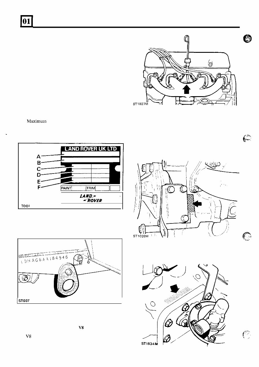
LOCATION OF VEHICLE IDENTIFICATION AND UNIT NUMBERS
VEHICLE IDENTIFICATION NUMBER (VIN)
The Vehicle Identification Number and the
recommended maximum vehicle weights are stamped
on a plate riveted to the top of the brake pedal box in
the engine compartment.
The number is also stamped on the right-hand side of
the chassis forward of the spring mounting turret.
Always quote this number when writing to Land Rover
Limited.
Key to Vehicle Identification Number Plate
A Type approval
B VIN (minimum of 17 digits)
C Maximum permitted laden weight for vehicle
D Maximum vehicle and trailer weight
E Maximum road weight - front axle
F Maximum road weight - rear axle
I
I
I
fAND
&IR
TOO1
ST037
I
ENGINE SERIAL NUMBER - VS ENGINE
The V8 engine serial number is stamped on a cast pad
on the cylinder block between numbers 3 and 5
cylinders.
6
ST
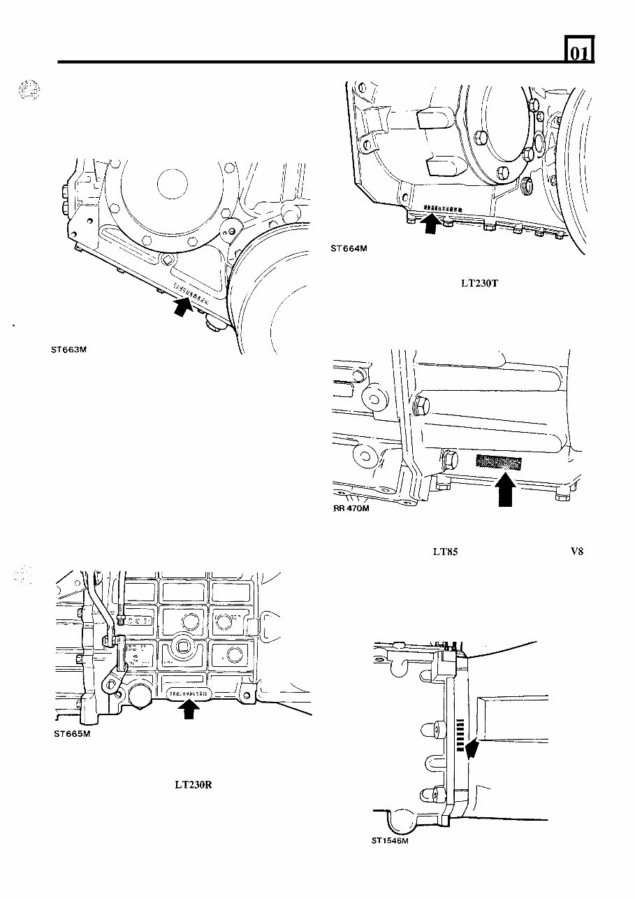
ENGINE SERIAL NUMBER - 4 CYLINDER
ENGINES
The 4 cylinder engine number is stamped on a
machined surface at the front left-hand side of the
On later engines the number is stamped above the rear
side cover, as the second illustration shows.
6”
engine adjacent to the exhaust manifold front flange.
-. -
LOCATION OF VEHICLE IDENTIFICATION AND UNIT NUMBERS
ST663M
01
FRONT AXLE
Stamped on top of the left-hand axle tube.
REAR AXLE
Stamped on rear of left-hand axle tube.
MAIN GEARBOX LT77 - 4 CYLINDER VEHICLES
Stamped on a pad on the right-hand side of the gearbox
immediately below the oil filler level plug.
U
ST665M
TRANSFER GEARBOX LT230R - 4 CYLINDER
VEHICLES
Stamped on the casing on the left-hand side of the
gearbox below the mainshaft rear bearing housing
adjacent to the bottom cover.
Y
ST664M
TRANSFER GEARBOX LT230T - 4 CYLINDER
AND V8 VEHICLES FROM SERIAL NUMBER
SUFFIX ‘B’ ONWARD
MAIN GEARBOX LT85 FIVE SPEED - V8
VEHICLES
Stamped on the right-hand side of the front bearing
plate.
STl546M
7
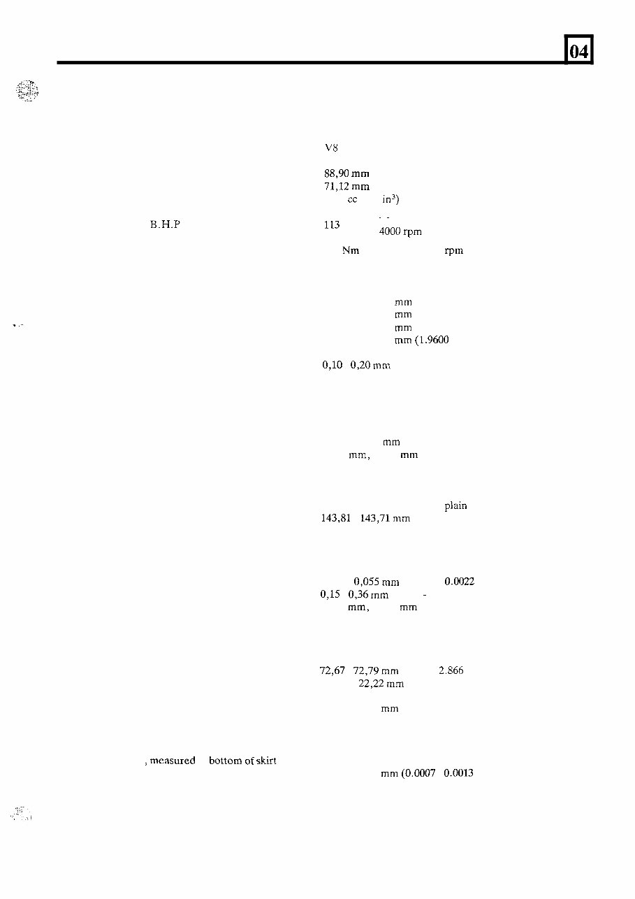
GENERAL SPECIFICATION DATA
ENGINE
Type .................................................................
Number of cylinders .............................................
Bore .................................................................
Stroke ...............................................................
Capacity ............................................................
Valve operation.. .................................................
Maximum power- B.H.P .....................................
Maximum power - KW.. ......................................
Maximum torque .................................................
04
V8
Eight, two banks of four
88,90 mm (3.500 in)
71,12 mm (2.800 in)
3528 cc (215 in')
Overhead by push-rod
._
'13 } at 4000rpm
84.6
251 Nm (185 lb ft) at 2500 rpm
Crankshaft
Main journal diameter .......................................
Minimum regrind diameter ..............................
Crankpin journal diameter.
Minimum regrind diameter ..............................
Crankshaft end thrust ........................................
Crankshaft end-float ..........................................
58,409 - 58,422 mm (2.2996 - 2.3001 in)
57,393 - 57,406 mm (2.2596 - 2.2601 in)
50,800 - 50,812 mm (2.0000 - 2.0005 in)
49,784 - 49,797 mm (1.9600 - 1.9605in)
Taken on thrust washers of centre main bearing
0,lO - 0,20 mm (0.004 - 0.008 in)
..
.................................
Main bearings
Number and type .............................................. 5, Vandervell shells
0,010 - 0,048 mm (0.0004 - 0.0019 in)
0,254 mm, 0,508 mm (0.010 in, 0.020 in)
Material ......................................................... Lead-indium
Diametrical clearance ........................................
Undersizes ......................................................
Connecting rods
Type.. ............................................................ Horizontally split big end, pIain small end
Length between centres ...................................... 143,81 - 143,71 mm (5.662 - 5.658 in)
Big end bearings
Type and material .............................................
Diametrical clearance ....................................... 0,015 - 0,055 mm (0.0006 - 0.0022 in)
End-float on crankpin ....................................... 0,15 - 0,36 mm (0.006 - 0.014 in)
Undersizes ......................................................
Vandervell VP lead-indium
0,254 mm, 0,508 mm (0.010 in, 0.020 in)
Gudgeon pins
Length ........................................................... 72,67 - 72,79 mm (2.861 - 2.866 in)
Fit-in connecting rod .........................................
Clearance in piston ............................................ 0,002 - 0,007 mm (0.0001 - 0.0003 in)
Diameter ........................................................ 22,215 - 22,22 mm (0.8746 - 0.8749 in)
Press fit
Pistons
Clearance in bore measlured at hottom of skirt at
right angles to gudgeon pin .................................. 0,018 - 0,033 mm (0.0007 - 0.0013 in)
1
You're Reading a Preview
What's Included?
Fast Download Speeds
Online & Offline Access
Access PDF Contents & Bookmarks
Full Search Facility
Print one or all pages of your manual
$41.99
Viewed 59 Times Today


Secure transaction
What's Included?
Fast Download Speeds
Online & Offline Access
Access PDF Contents & Bookmarks
Full Search Facility
Print one or all pages of your manual
$41.99
This is a comprehensive service and repair manual for the Land Rover Defender 110 spanning the years 1983 to 1990. It provides all the necessary information and details to assist in troubleshooting and maintaining the vehicle for optimal performance.
The manual is an invaluable resource suitable for both professional mechanics and DIY enthusiasts, offering insights into the vehicle and preventive maintenance measures.
The Land Rover Defender 110 1983-1990 Service Repair Manual includes:
- Introduction
- General Specification Data
- Engine Tuning Data
- Torque Wrench Settings
- General Fitting Instructions
- Recommended Lubricants, Fluids and Capacities
- Maintenance
- Engine
- Fuel System (including Fuel Injection)
- Cooling System
- Clutch
- Manual Gearbox and Transfer Box
- Propeller Shafts
- Rear Axle and Final Drive
- Steering
- Suspension
- Brakes
- Electrical
Format: PDF
Language: English
Compatibility: Win95/98/ME/XP/vista/7/8/Linux/MAC, IOS, Android
Delivery: Instant download via email, no shipping costs or waiting time.
Additional information:
- Land Rover Defender 110 1983-1990 Workshop Manual
- Land Rover Defender 110 1983-1990 Repair Manual
- Land Rover Defender 110 1983-1990 Maintenance Manual
- Land Rover Defender 110 1983-1990 Factory Manual
- Land Rover Defender 110 1983-1990 Shop Manual
- Land Rover Defender 110 1983-1990 Technical Manual


