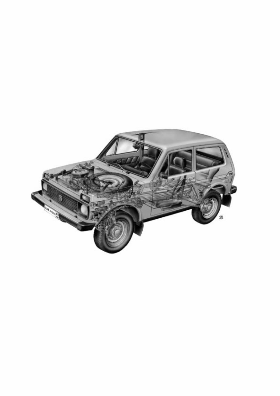
About this manual This Manual provides information on routine maintenance and servicing and is intended for engineers and mechanics of service outlets, garages and workshops. The Manual covers the following models: VAZ-21213 model - an off-road vehicle, three-door body of all-steel unitary construction, with 1.7 litre carburettor engine; VAZ-21214 model - with 1.7 litre Central Fuel Injection Engine; VAZ-21214-20 model - with 1.7 litre Sequential Fuel Injection Engine; VAZ-21215 model - with Turbo Diesel Engine. The chapters of the manual give full descriptions of VAZ-21213 vehicle units. For general description, service and repair procedures applicable to other models, refer to Section 9 where you can also find the information on additional and alternative equipment fitted to the vehicles. The Manual provides a detailed description of service operations on the base of OEM parts, with help- ful information on fault diagnosis, along with clear indications on removal and refitting, dismantling and reassembly, adjustment and repair of various vehicle units. We recommend to use special tools and working facilities as listed in Attachment No 2. Tighten the thread connections to torques specified in Attachment No 1. Basic adjustments and inspection checks are outlined in Attachment No 3. Refer to Attachment 4 for recommended lubricants and fuels. Due to the on-going process of vehicle improvement aimed to enhance the VAZ vehicle reliability and performance, the manufacturer can make alterations and design changes which may fail to enter this pub- lication. Such changes and alterations will be incorporated into our manuals at the earliest opportunity. The Manual describes the vehicle design as of October 1999. 3
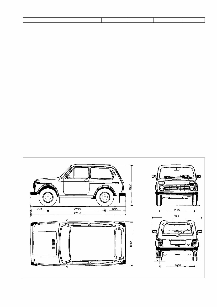
Section 1. General Data Table 1-1 TECHNICAL SPECIFICATION Features VAZ-21213 VAZ-21214 VAZ-21214-20 VAZ-21215 General Number of seats 5 5 5 5 Kerb weight, kg 1210 1210 1210 1240 Payload, kg 400 400 400 400 Overall dimensions Fig.1-1 Maximum braking distance at GVW and 80 km/h on horizontal dry flat asphalt road, not greater, meters: • with service braking system applied 40 40 40 40 • with emergency system applied (either of two service braking circuits) 90 90 90 90 Maximum speed* in top gear, km/h: • with driver and passenger 137 137 137 130 • at full load 135 135 135 128 Acceleration time*, 0 to 100 km/h through gear shifting, seconds: • with driver and passenger 19 19 19 22 • at full load 21 21 21 24 Engine Model 21213 21214 21214-10 DHW (XUD-9SD) Type Four-stroke, Four-stroke, Four-stroke, Four-stroke, petrol, carburettor petrol, CFI petrol, sequential injection turbo diesel No of cylinders four in-line four in-line four in-line four in-line Bore x stroke, mm 82ı80 82ı80 82ı80 83ı88 Capacity, litre 1.69 1.69 1.69 1.905 Compression ratio 9.3:1 9.3:1 9.3:1 21.5:1 Maximum power: as per GOST 14846 (net), at least, ÍW (h.p.) 58 (78.9) 58 (78.9) 58.5 (79.6) 55 (74.8) as per ISO 1585, ÍW 58 58 58.5 55 Maximum crankshaft speed at maximum power, rpm 5200 5400 5000 4600 Firing order 1-3-4-2 1-3-4-2 1-3-4-2 1-3-4-2 ____________________________________ * Measured using a special procedure 4
Features VAZ-21213 VAZ-21214 VAZ-21214-20 VAZ-21215 Power train Clutch single dry plate, diaphragm spring Clutch release mechanism hydraulic, servo spring Transmission 5-speed, synchro units on all forward gears Gear ratio: • first gear 3.67 3.67 3.67 3.67 • second gear 2.10 2.10 2.10 2.10 • third gear 1.36 1.36 1.36 1.36 • fourth gear 1.00 1.00 1.00 1.00 • fifth gear 0.82 0.82 0.82 0.82 • reverse gear 3.53 3.53 3.53 3.53 Transfer case two-gear, lockup differential Gear ratio: • top gear 1.2 1.2 1.2 1.2 • bottom gear 2.135 2.135 2.135 2.135 Transfer case differential bevel gears, two pinion gears Drive line: • from transmission to transfer case flexible coupling and CV joints • from transfer case to front and rear axles two universal joints on needle bearings with grease nipples and yokes • from front axle to wheels open, with CV joints Final drive ratio, front and rear axles bevel, hypoid • gear ratio 3.9 3.9 3.9 3.9 • differential bevel, two pinion gears Suspension and wheels Front suspension independent, lower track control arms (wishbones), coil springs, hydraulic telescopic shock-absorbers, anti-roll bar Rear suspension rigid axle beam with Panhard rod and four trailing arms, coil springs/hydraulic telescopic shock-absorbers Wheels pressed-steel disc • wheel rim 127J x 406 (5J x 16) Tyres tubed, cross-ply or radial ply size: • cross-ply tyres 175 x 406 (6.95 x16), • radial-ply tyres 175/80R16 5
Features VAZ-21213 VAZ-21214 VAZ-21214-20 VAZ-21215 Steering Steering mechanism globoidal worm, double-crest roller, steering ratio 16.4 Steering linkage three links, relay rod and two steering rods, drop arm, idler arm and swing arms Braking system Service braking system: • front brakes disc-type, floating caliper, automatic disc-to-pad clearance adjustment • rear brakes drum-type, self-applying shoes and automatic shoe-to-drum clearance adjustment • brake operation line foot-type, hydraulic, dual circuit, split diagonally, vacuum servo unit and pressure regulator Handbrake cable-operated on rear wheels Electrical system Wiring diagram single-wire, negative earth type Voltage, volts 12 Battery 6ëí-55Ä, 55 ampere-hour Alternator AC, integral diode plate and electronic voltage regulator Starter motor pre-engaged, solenoid switch and overrun clutch Body Type all-steel unitary construction, monocoque, three-door, double-space 6 Fig.1-1. Basic overall dimensions of VAZ-21213 vehicle
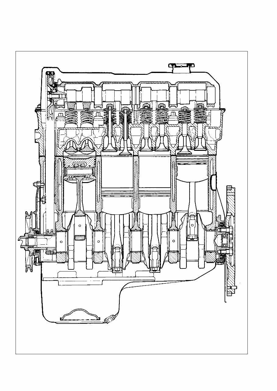
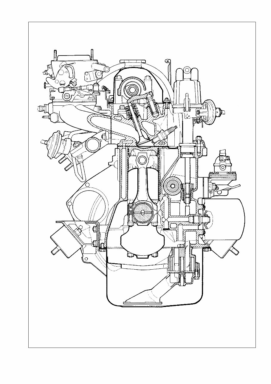
Section 2. Engine Refer to Fig.2-1 and Fig.2-2 for front and side sectional views of the engine. 7 Fig.2-1. Side sectional view of the engine
8 Fig.2-2. Front sectional view of the engine
Fault diagnosis Symptom/fault Remedy Engine fails to start 1. No fuel to carburettor: - blocked fuel pipes or fuel filter; - clogged carburettor or fuel pump filters; - faulty fuel pump 2. Ignition system fault 3. Carburettor fuel cutoff solenoid fails to open at ignition switch-on: - disconnected, loose or broken wiring to solenoid or solenoid control unit; - faulty solenoid control unit; - defective fuel cutoff solenoid 4. Carburettor choke not opening at first flashes in cylinders Engine idles erratically or stalls 1. Incorrectly adjusted idle speed 2. Defective carburettor solenoid control system 3. Faulty carburettor: - blocked carburettor jets or internal passages; - water in carburettor; - broken choke control diaphragm 4. Ignition system fault 5. Vacuum leak through damaged hose between intake pipe and brake servo unit 6. Air leak through gaskets at connections between intake pipe and car- burettor/cylinder head 7. Leaking distributor vacuum pipe Engine lacks power and has poor acceleration 1. Partly open throttle 2. Choked air cleaner element 3. Ignition system fault 4. Faulty fuel pump 5. Faulty carburettor: - faulty accelerator pump; - blocked main jets; - partly open choke; - low fuel level in float chamber; - leaky throttle enrichment diaphragm 6. Restricted fuel tank vent pipe 7. Incorrect valve clearances 8. Misaligned timing marks 9. Insufficient cylinder compression - below 1 åP‡ (10 kgf/Òm 2 ): - broken or sticking piston rings; - poor valve-to-seat fitting; - excessively worn cylinders or piston rings 9 1. Carry out the following operations: - blow fuel pipes, clean fuel tank, renew fuel filter; - clean filters; - check pump operation and renew any damaged components 2. Refer to section «Ignition system» 3. Carry out the following: - check wiring and connections, renew damaged wires; - renew control unit; - replace solenoid with a new one 4. Eliminate any leakage of choke pull-down unit 1. Adjust idle speed 2. Refer to «Engine fails to start» 3. Carry out the following: - blow carburettor jets and internal passages; - remove water from carburettor, drain sludge from fuel tank; - fit new diagram 4. Refer to section «Ignition system» 5. Replace damaged hose 6. Tighten retaining nuts or renew gaskets; eliminate carburettor flange deformation or fit new carburettor 7. Fit new pipe in place of damaged one 1. Adjust throttle linkage 2. Change filter element 3. Refer to section «Ignition system» 4. Check pump operation and renew any damaged components 5. Carry out the following: - check pump operation, renew damaged parts; - blow jets with compressed air; - adjust choke operation; - adjust float; - replace diaphragm 6. Blow pipe with compressed air 7. Adjust valve clearances 8. Adjust timing belt accordingly, align timing marks 9. Carry out the following: - clean piston rings or grooves from carbon deposits, renew damaged com- ponents; - replace damaged valves, regrind valve seats; - replace pistons, rebore and hone cylinders.
Main bearing knocking Typical knocking or thumping noticeable at sudden throttle opening at idle which intensifies with higher crankshaft rate. Excessive endfloat of crankshaft causes sharper irregular knocking, especially noticeable during smooth increase or decrease in crankshaft speed. 1. Early ignition 2. Insufficient pressure oil 3. Loose flywheel securing bolts 4. Excessive main bearing running clearance 5. Excessive thrust washers-to-crankshaft clearance Big-end bearing knocking Big-end bearing knocking is sharper than that of main bearings. It is noticeable during engine idle at sudden throttle opening. The origin of knocking can be easily identified through switching off spark plugs one at a time. 1. Insufficient oil pressure 2. Excessive big-end bearing running clearance Piston slap Thumping noise caused by piston «runout» in cylinder. Most noticeable at low crankshaft speed and under load. 1. Excessive piston-to-cylinder bore clearance 2. Excessive gudgeon pin-to-piston groove clearance Knocking of intake or exhaust valves Excessive valve clearances cause typical regular noise; its frequency is lower than the frequency of any other engine noise, since the valves are operated by camshaft rotating at half the crankshaft speed. 1. Excessive valve clearances 2. Broken valve spring 3. Excessive valve-to-guide clearance 4. Worn camshaft lobes 5. Loose locknut of adjuster bolt Excessive noise of camshaft operation line Noise from camshaft operation line is caused by clearances between engagement elements and becomes noticeable in general engine noise at low crankshaft speed. 1. Loose chain caused by general wear 2. Broken chain tensioner shoe or damper 3. Seized chain tensioner plunger rod Insufficient oil pressure at warm engine idle 1. Foreign particles entrapped under oil pump relief valve 2. Seized oil pressure relief valve 3. Worn oil pump gears 4. Excessive main bearing running clearance 5. Excessive camshaft bearing journal-to-bearing housing clearance 6. Incorrect oil grade or inappropriate oil quality Excessive oil pressure on warm engine 1. Seized oil pressure relief valve 2. Excessively tough spring of oil pressure relief valve 10 1. Adjust ignition timing 2. Refer to subsection «Insufficient oil pressure at idle» 3. Tighten bolts to torque specified 4. Grind journals and renew bearing shells 5. Fit new thrust washers, check clearance 1. Renew valve 2. Renew spring 1. Refer to «Insufficient oil pressure at idle» 2. Fit new bearing shells and regrind journals 1. Adjust clearances 2. Renew spring 3. Replace worn parts 4. Renew camshaft and levers 5. Adjust clearance between lever and cam, tighten locknut 1. Renew pistons, rebore and hone cylinders 2. Fit new rings or new pistons with rings 1. Tighten chain 2. Renew tensioner shoe or damper 3. Eliminate seizure 1. Clean valve from foreign particles and flash, clean oil pump 2. Renew valve 3. Repair oil pump 4. Turn journals and renew bearing shells 5. Renew camshaft or bearing housing 6. Change oil as recommended in Attachment 4
The LADA NIVA Service Repair Manual is a comprehensive guide for maintaining and repairing your LADA NIVA vehicle. Whether you are a DIY enthusiast or a professional mechanic, this manual provides you with detailed instructions and diagrams to ensure that your vehicle is in optimal condition.
This service repair manual covers various models of the LADA NIVA, including:
LADA NIVA 1600
LADA NIVA 1700
LADA NIVA 4x4
With this manual, you will have access to step-by-step procedures for troubleshooting, repair, and maintenance tasks. From engine repairs to electrical system diagnostics, this manual has got you covered. It also includes specifications, torque settings, and recommended fluid types for various components.
Whether you need to replace a faulty part or perform routine maintenance, the LADA NIVA Service Repair Manual will be your go-to resource. With clear instructions and illustrations, you can confidently tackle any repair task and keep your LADA NIVA running smoothly.