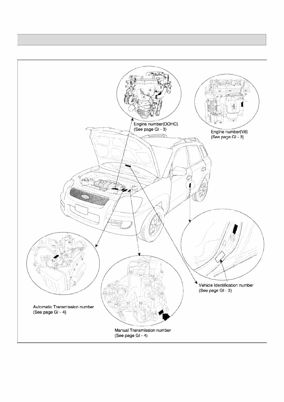
SPORTAGE(KM) > 2009 > G 2.0 DOHC > General Information General Information > General Information > General Information Identification Number Locations Identification Number Description Vehicle Identification Number Page 1 of 28
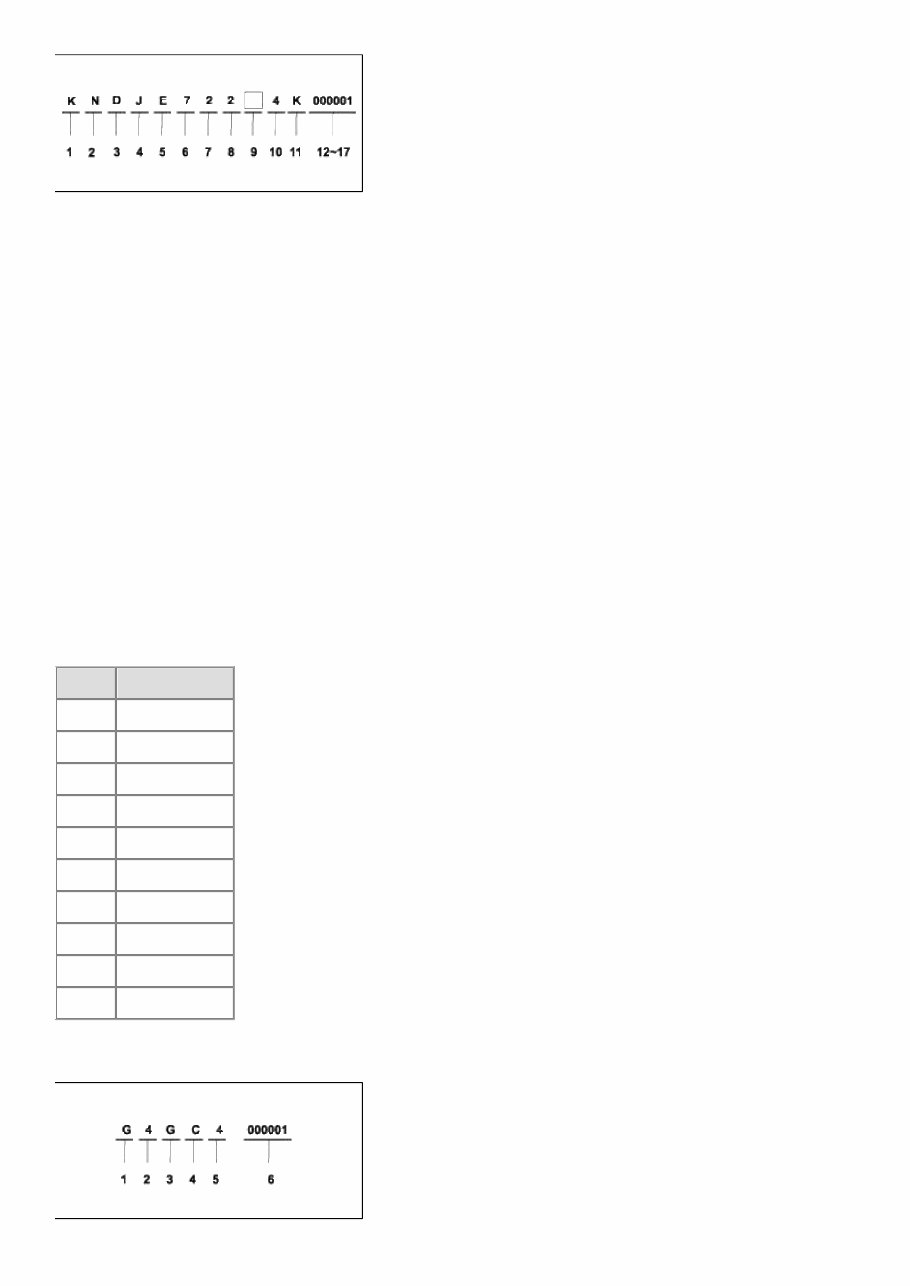
1 - 3 : Make / Vehicle type - KND = Kia MPV 4 - 5 : Vehicle Line /Series - JE = SPORTAGE 4x4 - JF = SPORTAGE 4x2 6 - 7: Body type - 72 = 4Door Sport Utility Vehicle & GVW 1821 ~ 2270kg 8 : Engine type - 2 = 2.0 Gasoline (G4GC) (Federal) - 3 = 2.7 Gasoline (G6BA) - 4 = 2.0 Gasoline (G4GC) (California) 9 : Transmission type - Check digit 10 : Model year - 4 = 2004, 5 = 2005 11 : Plant location - K = Kwang-ju plant 12 - 17 : Sequential number - 000001 ~ 999999 Paint Code CODE COLOR UD Clear White S4 Grayish Silver S6 Satin Silver Y3 Greenish Gold 9L Natural Oliv 1L Vert Jade Pearl K6 Smart Blue 3P Volcanic Red 6D Smokey Brown 9D Black Cherry Engine Identification Number Page 2 of 28
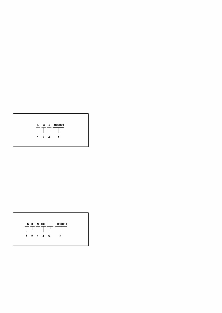
1. Engine fuel - G : Gasoline 2. Engine range - 4 : 4 cycle 4 cylinder - 6 : 4 cycle 6 cylinder 3. Engine development order - B : DELTA Engine - G : BETA Engine 4. Engine capacity - A : 2656cc (Gosoline) - C : 1975 cc (Gasoline) 5. Production year - 4 : 2004, 5 : 2005, 6 : 2006 6. Engine production sequence number - 000001 ~ 999999 Transmission Identification Number Manual 1. Model - L : M5GF1 2. Production year - 4 : 2004, 5 : 2005, 6 : 2006, 7 : 2007 3. Gear ratio - H : 4.063 - J : 4.533 4. Transaxle production sequence number - 000001 ~ 999999 Automatic 1. Modle - N : F4A42-2 2. Production year - 4 : 2004, 5 : 2005, 6 : 2006, 7 : 2007 3. Gear ratio - N : 4.042 - O : 4.407 - R : 4.626 Page 3 of 28
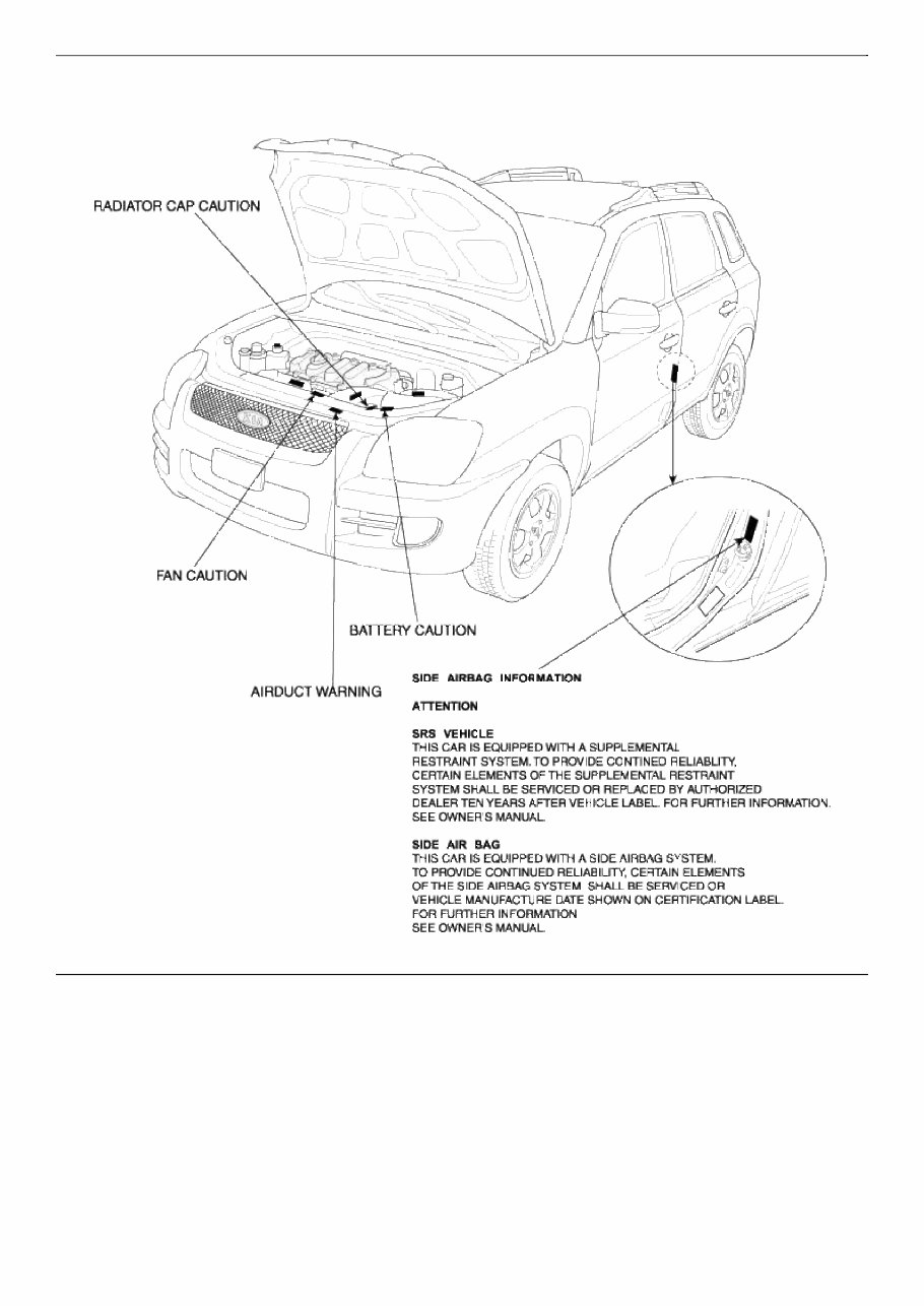
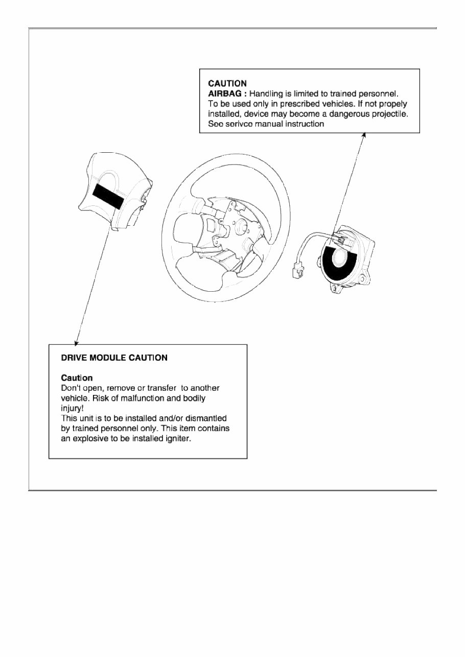
Air Bag Waring / Caution Label (Cont'd) Page 6 of 28
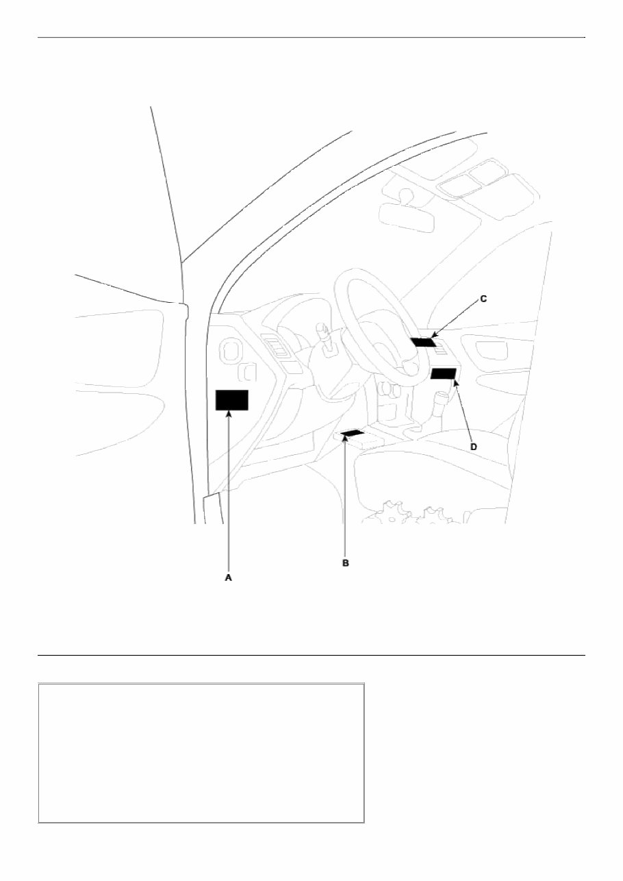
Warning / Caution Label (Cont'd) A : WARNING SEE OWNER'S MANUAL. This car is equipped a side airbag for each front seat. • Do not use any accessory seat covers. • Use of other seat covers could reduce the effect of the system. • Do not install any accessories on the side or near the side airbag. • Do not use excessive force on the side of the seat. • For further information, see the owner's manual. Page 7 of 28
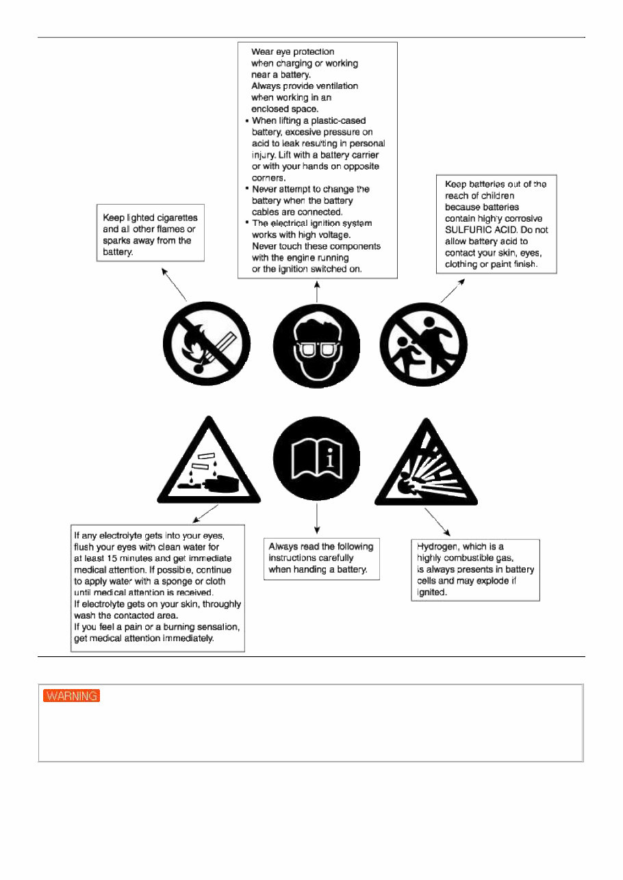
B : CAUTION AIRBAG ESPE UNIT Detach connector before unmounting. Assemble strictly according to manual instructions. C : PASSENGER MODULE CAUTION CAUTION Don't open, remove or transfer to another vehicle. Risk of malfunction and bodily injury! This unit is to be installed and/or dismantled by trained personnel only. This item contains an explosive to be installed igniter. D : SUPPLEMENTAL RESTRAINT SYSTEM (AIRBAG) INFORMATION • The airbag is a Supplement Restraint System (SRS). You must always wear the seat belts. • The airbag system condition is normal when the "SRS" lamp in the cluster flashes approximately 6 times after the ignition key is turned on and then goes off. • If any of the following condition occur, the system must be serviced. • "SRS" lamp does not light up when the key is turned on. • "SRS" lamp stays lit or flashes continuously. • The airbag has inflated. • The airbag system must be inspected by an authorized dealer ten years after the vehicle manufacture date shown on the certification label, located on left front door opening area. WARNING Failure to the above instructions may result in injury to you or other occupants in the vehicle • See the "SRS" section in Owner's Manual for more information about airbags. Battery Caution Label Describtion Page 8 of 28
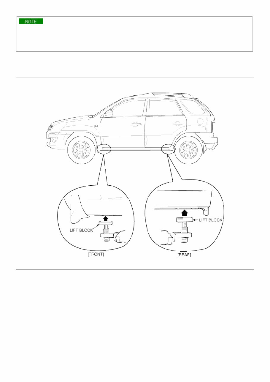
Lift And Support Points When heavy rear components such as suspension, fuel tank, spare tire, tailgate and trunk lid are to be removed, place additional weight in the luggage area before hoisting. When substatial weight is removed from the rear of the vehicle, the center of gravity may change and cam cause the vehicle to tip forward on the hoist. Page 9 of 28
• Since each tire/wheel assembly weights approximately 30lbs (14kg), placing the front wheels in the luggage area can assist with the weight distribution. • Use the same support points to support the vehicle on safety stands. 1. Place the lift blocks under the support points as shown in the illustration. 2. Raise the hoist a few inches (centimeters) and rock the vehicle to be sure it is firmly supported. 3. Raise the hoist to full height to inspect the lift points for secure support. Page 10 of 28
Our Service Repair Manual is an essential resource for both professional mechanics and DIY enthusiasts. Unlike the standard Owner's Manual, this comprehensive guide is typically exclusive to dealerships and auto shops. It features detailed illustrations and step-by-step instructions for a wide range of minor and major repairs, including fluid changes and transmission rebuilding.
This manual covers repair and maintenance procedures, wiring schematics, electrical diagrams, computer diagnostic codes, suspension, brakes, air bags, air conditioning, engine/transmission service, body work, and much more. It is designed to be user-friendly, requiring no software installation or specific computer requirements. The manual is available as a single PDF file with bookmarks, allowing for easy navigation and keyword searches.
Rest assured, we offer full support for all our products. If you encounter any issues or have questions, please don't hesitate to contact us. Our goal is to ensure 100% customer satisfaction.