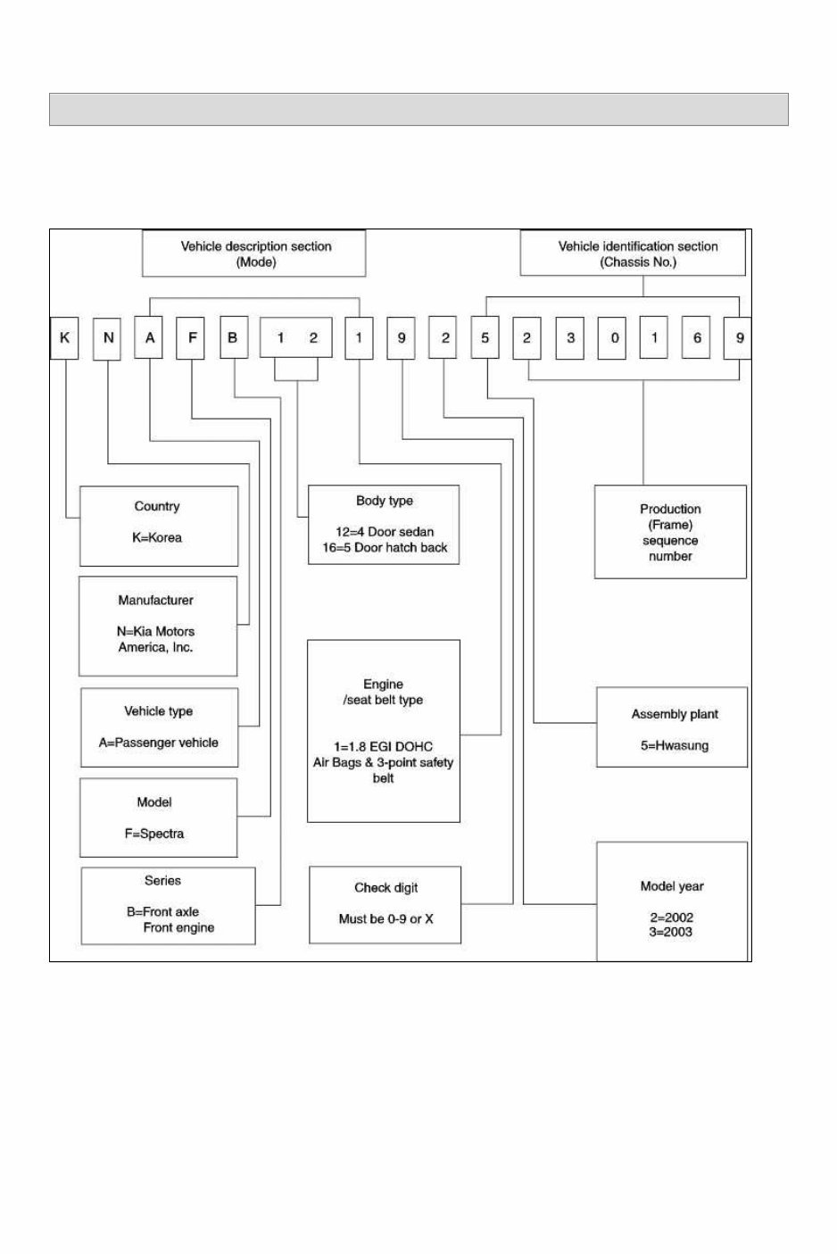
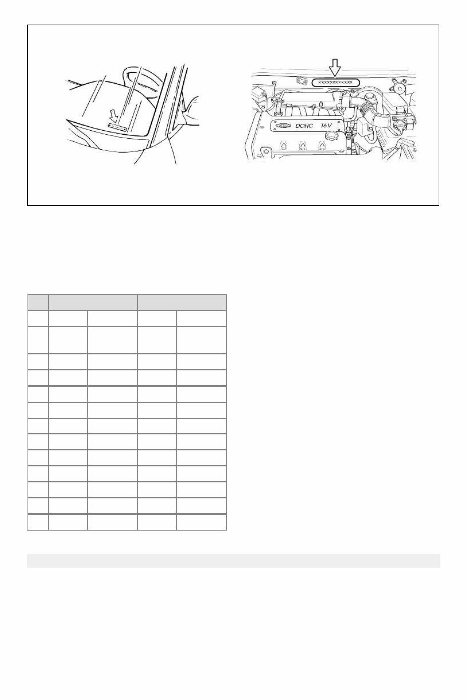
SPECTRA(SD) > 2003 > G 1.8 DOHC > General Information General Information > General Information > General Information Vehicle identification number (VIN) The vehicle identification number (VIN) for the Kia Spectra is a 17-digit stamped on a metal plate that is located on the driver's side of the instrument panel visible from outside of the vehicle through the windshield. The VIN is also stamped into the passenger side of the engine compartment bulkhead. The VIN is composed of the following codes: VIN LOCATIONS Page 1 of 18
VEHICLE CERTIFICATION LABEL The Vehicle Certification Label is affixed to the left-hand door jamb. The upper half of the label contains the name of the manufacturer, day, month and year of manufacture, Gross Vehicle Weight Rating (GVWR), Gross Axle Weight Rating (GAWR), and the certification statement. The Vehicle Certification Label also contains the Vehicle Identification Number (VIN). Following the VIN is the vehicle type, exterior paint color, body type, vinyl roof code, moulding color, interior trim color, tape stripe code, radio type, sunroof/moonroof code, transaxle ratio, and transaxle type. The following chart contains the available colors and codes. 4Door 5Door Kia code Paint color Kia code Paint color 1 C5 Diamond siver C5 Diamond siver 2 EB Ebony black EB Ebony black 3 R5 Pepper red R5 Pepper red 4 UD Clear white UD Clear white 5 VR Very red VR Very red 6 V9 Pewter gray V9 Pewter gray 7 3Y Soft gold 3Y Soft gold 8 6B Purplish blue 5C Oilve green 9 8Y Stone beige 5E Ever green 10 5C Olive green C4 Crystal silver 11 5E Ever green V5 Gray metallic 12 3B Steel blue Fundamental procedures Symbols There are six primary symbols used to complement illustrations. These symbols indicate the areas to apply such materials during service. Page 2 of 18
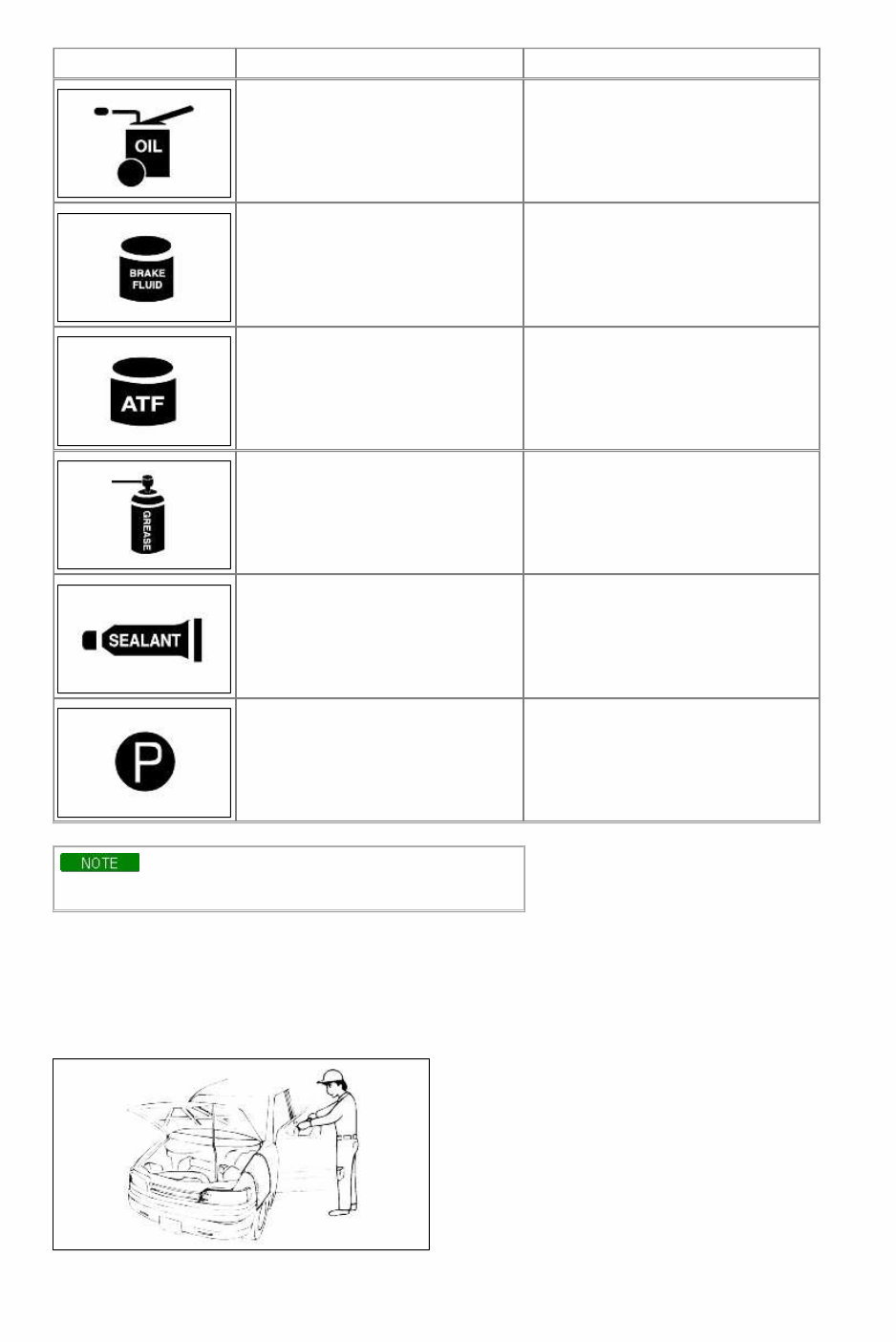
Symbol Meaning Type Apply oil New engine oil, gear oil, etc. as appropriate Apply brake fluid Only brake fluid Apply automatic transmission fluid (ATF) Only ATF Apply grease Appropriate grease Apply sealant Appropriate sealant Apply petroleum jelly Appropriate petroleum jelly Whenever special oil or grease is required, it will be identified in figure. NOTICES, CAUTIONS AND WARNINGS remind you to be especially careful in specific areas where carelessness can cause personal injury. The following items contain general procedures you should always follow when working on a vehicle. Protection of vehicle Always cover fenders, seats, and floor areas before starting work. Operate the engine only in a well-ventilated area to avoid carbon monoxide poisoning. Page 3 of 18
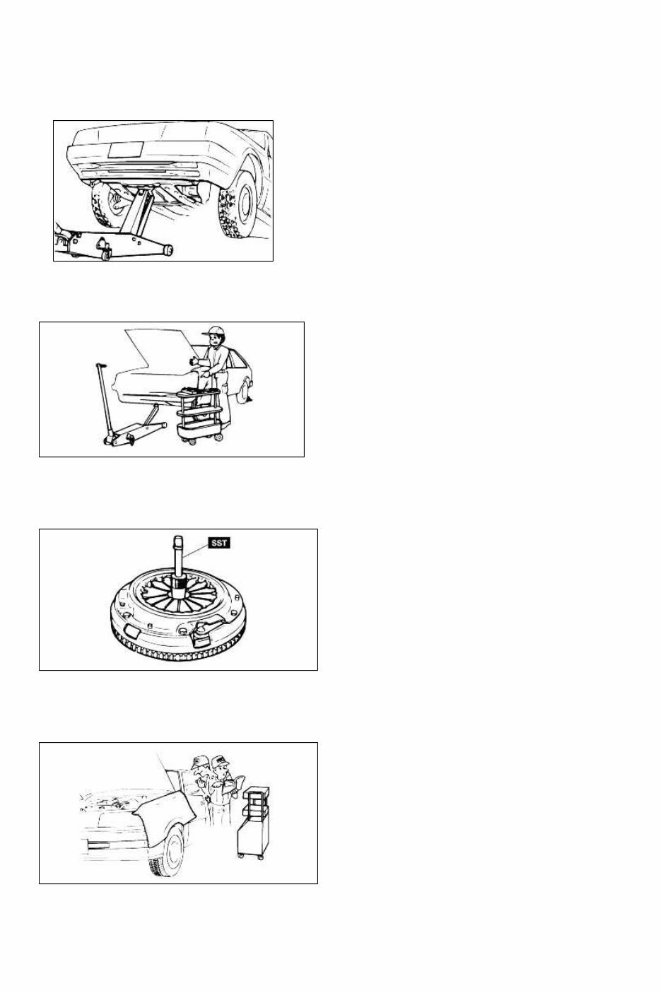
A word about safety The following precautions must be followed when jacking up the vehicle: 1. Block the wheels. 2. Use only the specified jacking positions. 3. Support the vehicle with safety stands. The engine compartment must be clear of tools and people before starting the engine. PREPARATION OF TOOLS AND MEASURING EQUIPMENT All necessary tools and measuring equipment should be available before starting any work. SPECIAL SERVICE TOOLS (SST'S) Use special service tools when they are required. SST's can be found under "preparation"prior to any procedure requiring them. Removal of parts Begin work only after first learning which parts and subassemblies must be removed and disassembled for replacement or repair. Disassembly If the disassembly procedure is complex, requiring many parts to be disassembled, all parts should be disassembled in a way that will not affect their performance or external appearance. Additionally, these parts should be identified so that Page 4 of 18
reassembly can be done easily and efficiently. Inspection of parts When removed, each part should be carefully inspected for malfunction, deformations, damage, or other problems. Arrangement of parts All disassembled parts should be carefully arranged for reassembly. Separate or otherwise identify the parts to be replaced from those that will be reused. Cleaning parts for reuse All parts that will be reused should be carefully and thoroughly cleaned using appropriate methods. REASSEMBLY Standard values, such as torques and certain adjustments, must be strictly observed in the reassembly of all parts. If removed, the following parts should be replaced with new ones: 1. Oil seals 2. O-rings 3. Cotter pins 4. Gaskets Page 5 of 18
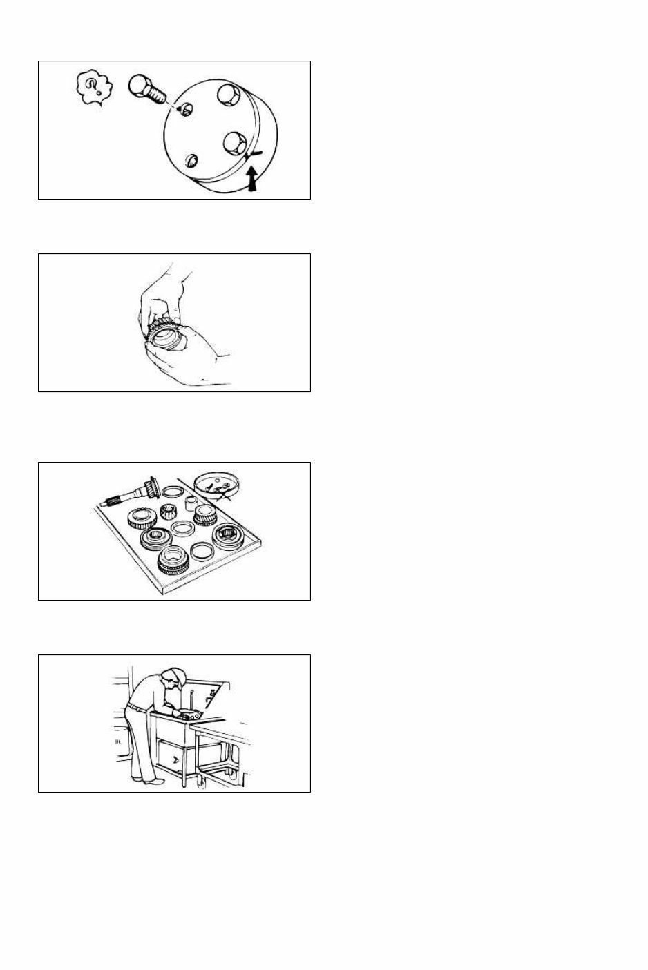
5. Lock washers 6. Nylon nuts Depending on location: 1. Sealant should be applied or new gaskets installed. 2. Oil should be applied to the moving components of parts. 3. Specified oil or grease should be applied at the appropriate locations (such as oil seals) before reassembly. Adjustments Use appropriate gauges and/or testers when making adjustments. Rubber parts and tubing Prevent gasoline or oil from contacting rubber parts or tubing. Electrical troubleshooting tools (Test Light) The test light, as shown in figure, uses a 12V bulb. The two lead wires should be connected to probes. The test light is used for simple voltage checks and in checking for short circuits. When checking the engine control module (ECM), never use a bulb exceeding 3.4W. Page 6 of 18
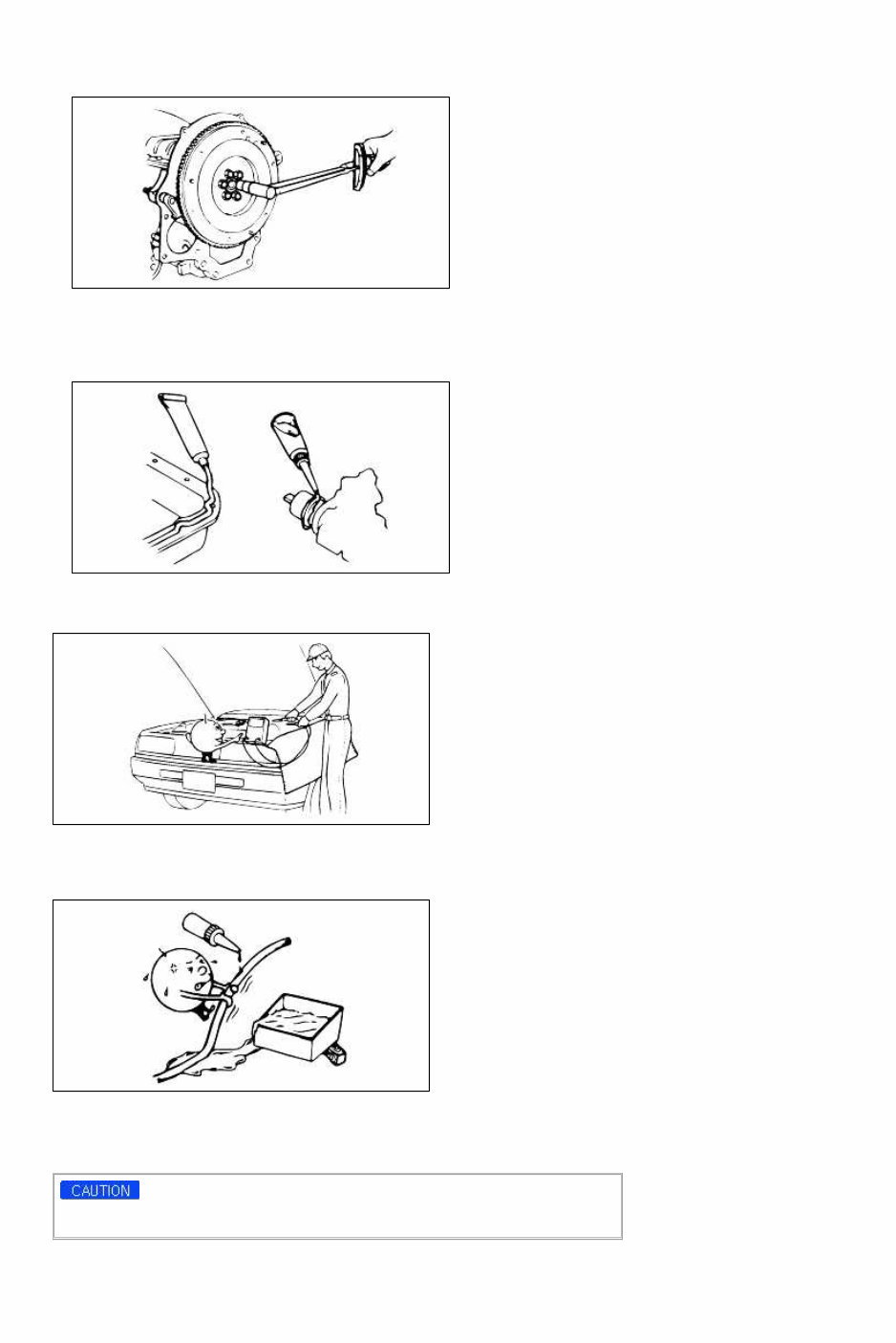
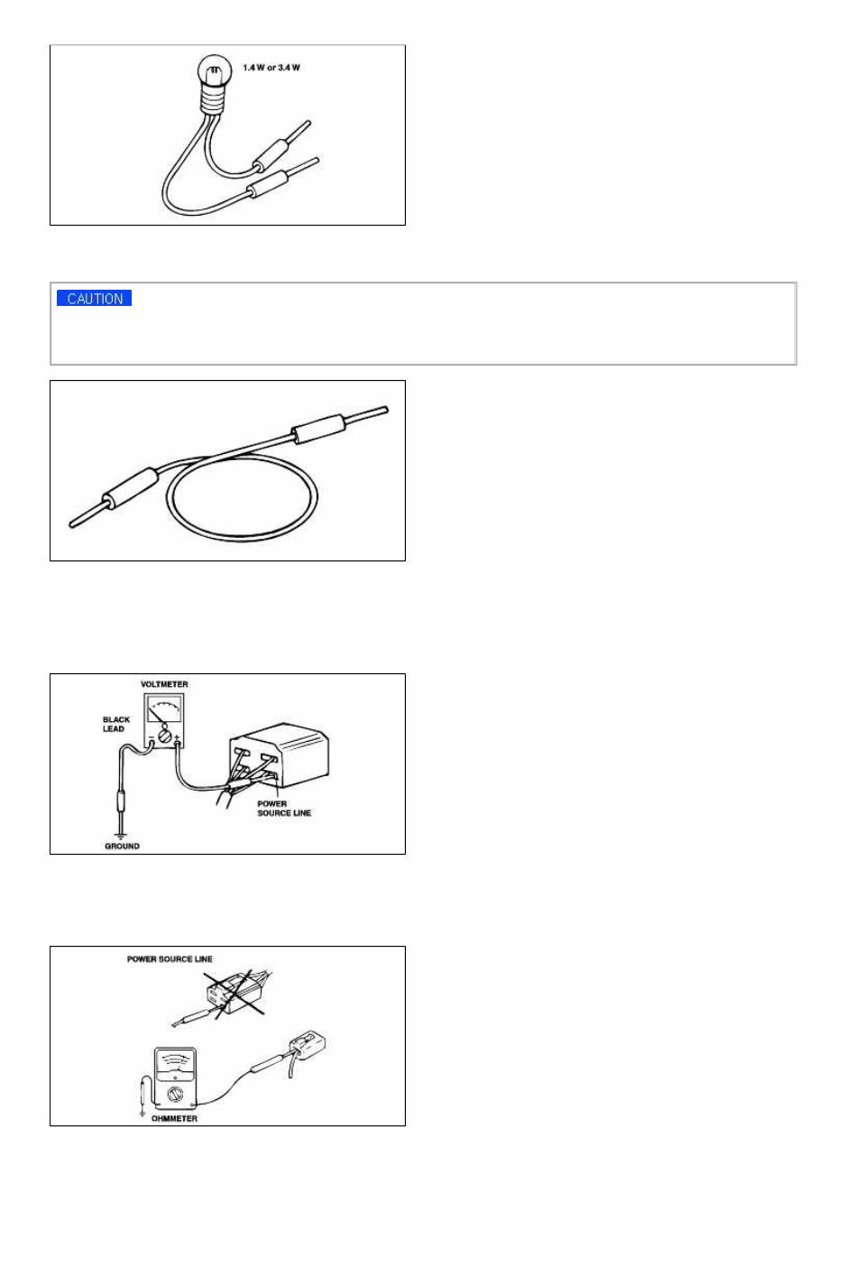
Electrical troubleshooting tools(Jumper wire) The jumper wire is used for testing by shorting across switch terminals and ground connections. Do not connect a jumper wire from the power source line to a body ground. Such a connection may cause damage to harnesses or electronic components. Electrical troubleshooting tools(Voltmeter) The DC voltmeter measures circuit voltage. A voltmeter with a range of 15V or more is used by connecting the positive (+) probe (red lead wire) to the point where voltage is to be measured, and the negative (-) probe (black lead wire) to a body ground. Electrical troubleshooting tools(Ohmmeter) The ohmmeter is used to measure the resistance between two points in a circuit and also to check for continuity and the diagnosis of short circuits. Page 7 of 18
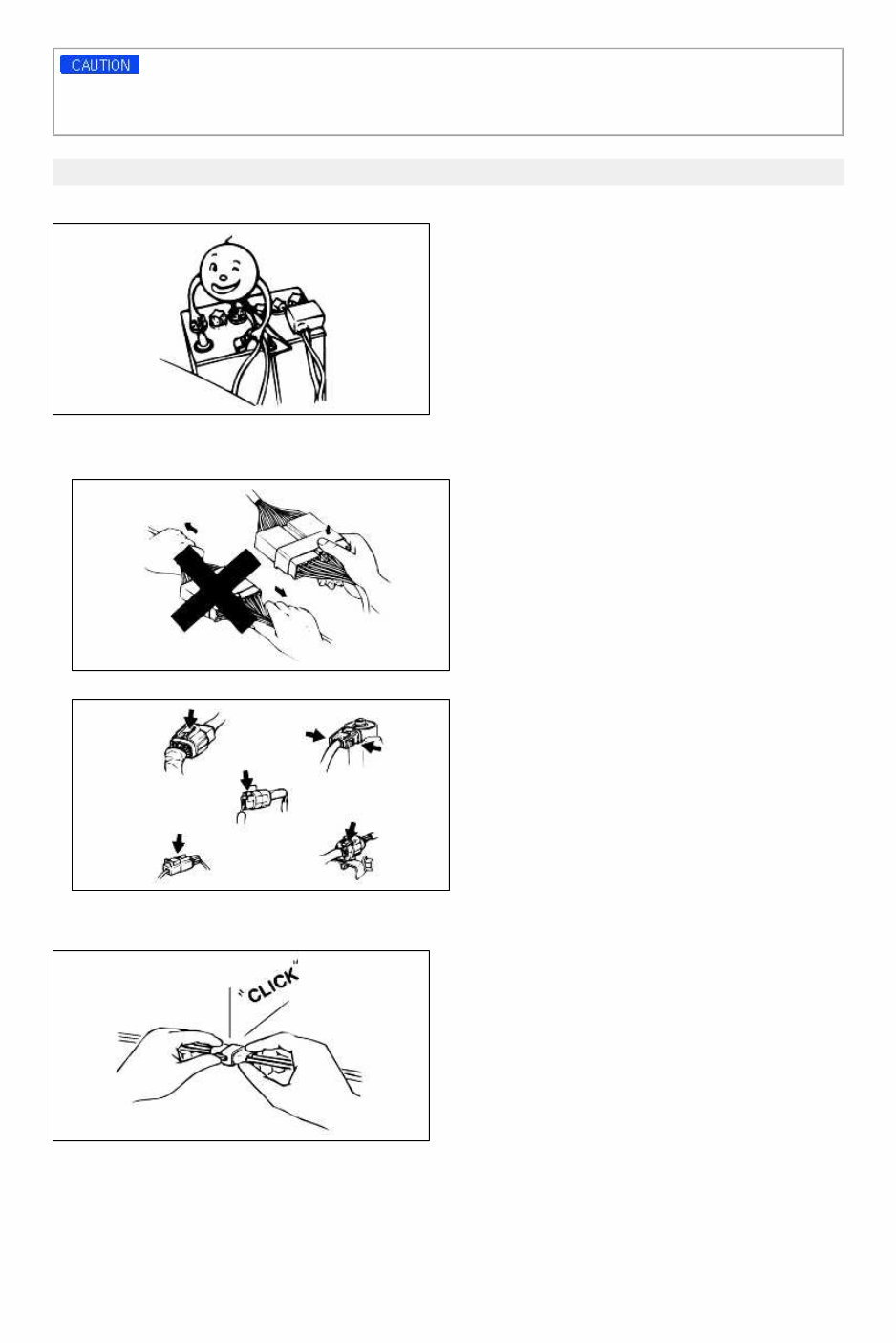
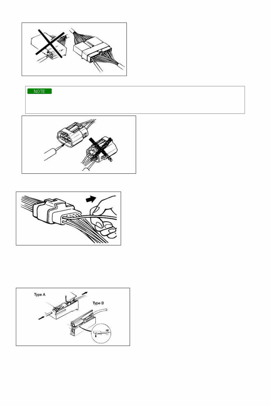
Do not attempt to connect the ohmmeter to any circuit in which voltage is applied. Such a connection may damage the ohmmeter. Electrical parts Battery cable Before disconnecting connectors or replacing electrical parts, disconnect the negative battery cable. Connectors(Removal of connector) 1. Never pull on the wiring harness when disconnecting connectors. 2. Connectors can be removed by pressing or pulling lock lever. Connectors(Locking a connector) Listen for a click when locking connectors. This sound indicates that they are securely locked. Connectors(Inspection) Page 8 of 18
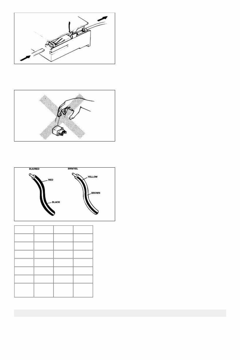
1. When a tester is used to check for continuity or to measure voltage, insert tester probe from wire harness side. 2. Check terminals of waterproof connectors from connector side because they cannot be accessed from harness side. • Use a fine wire to prevent damage to the terminal. • Do not damage the terminal when inserting the tester lead. Terminals(Inspection) Pull lightly on individual wires to ensure that they are secured in the terminal. Terminals(Replacement of terminals) Use appropriate tools to remove terminal as shown. When installing the terminal, insert it until it locks securely. <Female> Insert a thin piece of metal from the terminal side of the connector, and then, with the terminal locking tab pressed down, pull the terminal out of the connector. <Male> Follow the same procedure as female-type terminal. Page 9 of 18
SENSORS, SWITCHES, AND RELAYS Always handle sensors, switches and relays carefully. Do not drop them or accidentally strike them against other parts. WIRING COLOR CODES Two-color wires are indicated by a two-color code sysmbol. The first color indicates the base color of the wire; the second color indicates the color of the stripe. Code Color Code Color BLK Black ORN Orange BRN Brown PNK Pink GRN Green RED Red GRY Gray VIO Violet BLU Blue WHT White LT BLU Light blue YEL Yellow LT GRN Light green LT GRY Light gray JACK AND SAFETY STAND POSITIONS FRONT END Jack position: At the front crossmember Page 10 of 18
This is the complete official full factory service repair manual for the Kia Spectra 2003. It provides detailed information for general maintenance, troubleshooting, engine and transmission service/repair, brake system, wiring diagram, electrical system, suspension, periodic lubrication, steering, cooling system, fuel injection, fuel system, emission system, heater/air conditioning, engine control system, chassis/body, restraint system, interior, differential/drive, and axle. This manual is useful for both professional mechanics and DIY enthusiasts.
The manual comes in .PDF format and can be printed or viewed on PC-based Windows operating systems and Mac. It contains step-by-step instructions, detailed illustrations, and photos to guide you through each service and repair procedure. Additionally, it includes information on diagnosing and repairing electrical system problems, along with troubleshooting and electrical service procedures combined with detailed wiring diagrams for ease of use.
Product Details:
File Format: .PDF
Language: English
Printable: Yes
Delivery: Link will appear on the checkout page after payment is complete
Requirements: Adobe Reader
This is a comprehensive service and repair manual for the Kia Spectra 2003, covering a wide range of topics including specifications, engine removal, periodic maintenance, tune-up procedures, disassembly, reassembly, and much more. It is a valuable resource for maintaining and servicing your vehicle.