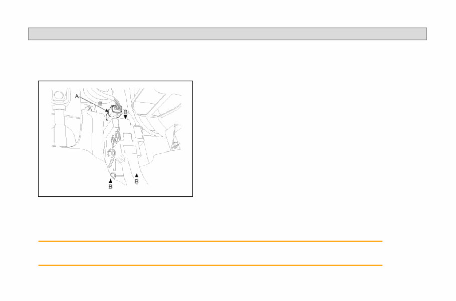
SORENTO(BL) >2008 > G 3.8 DOHC > Fuel System REMOVAL 1. Turn ignition switch off and disconnect the battery (-) cable from the battery. 2. Disconnect the accelerator position sensor connector (A). 3. Unfasten the mounting bolt/nuts (B) and remove the accelerator pedal from the vehicle. INSTALLATION 1. Install the accelerator pedal in according to the reverse order of "REMOVAL" procedure. Accelerator pedal mounting nuts: 7.8 ~ 11.8N·m (0.8 ~ 1.2kgf·m, 5.8 ~ 8.7lbf·ft) Page 1 of 1
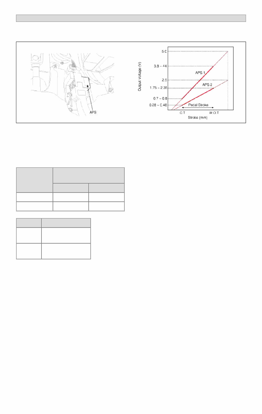
SORENTO(BL) >2008 > G 3.8 DOHC > Fuel System INSPECTION FUNCTION AND OPERATION PRINCIPLE Accelerator Position Sensor (APS) is installed on the accelerator pedal module and detects the rotation angle of the accelerator pedal. The APS is one of the most important sensors in engine control system, so it consists of the two sensors which adapt individual sensor power and ground line. The second sensor monitors the first sensor and its output voltage is half of the first one. If the ratio of the sensor 1 and 2 is out of the range (approximately 1/2), the diagnostic system judges that it is abnormal. SPECIFICATION Pedal Position Output Voltage (V) [Vref = 5.0V] APS1 APS2 C.T 0.7 ~ 0.8 0.28 ~ 0.48 W.O.T 3.8 ~ 4.4 1.75 ~ 2.35 Item Sensor Resistance APS1 0.7 ~ 1.3kΩ at 20°C (68°F) APS2 1.4 ~ 2.6kΩ at 20°C (68°F) SCHEMATIC DIAGRAM Page 1 of 4
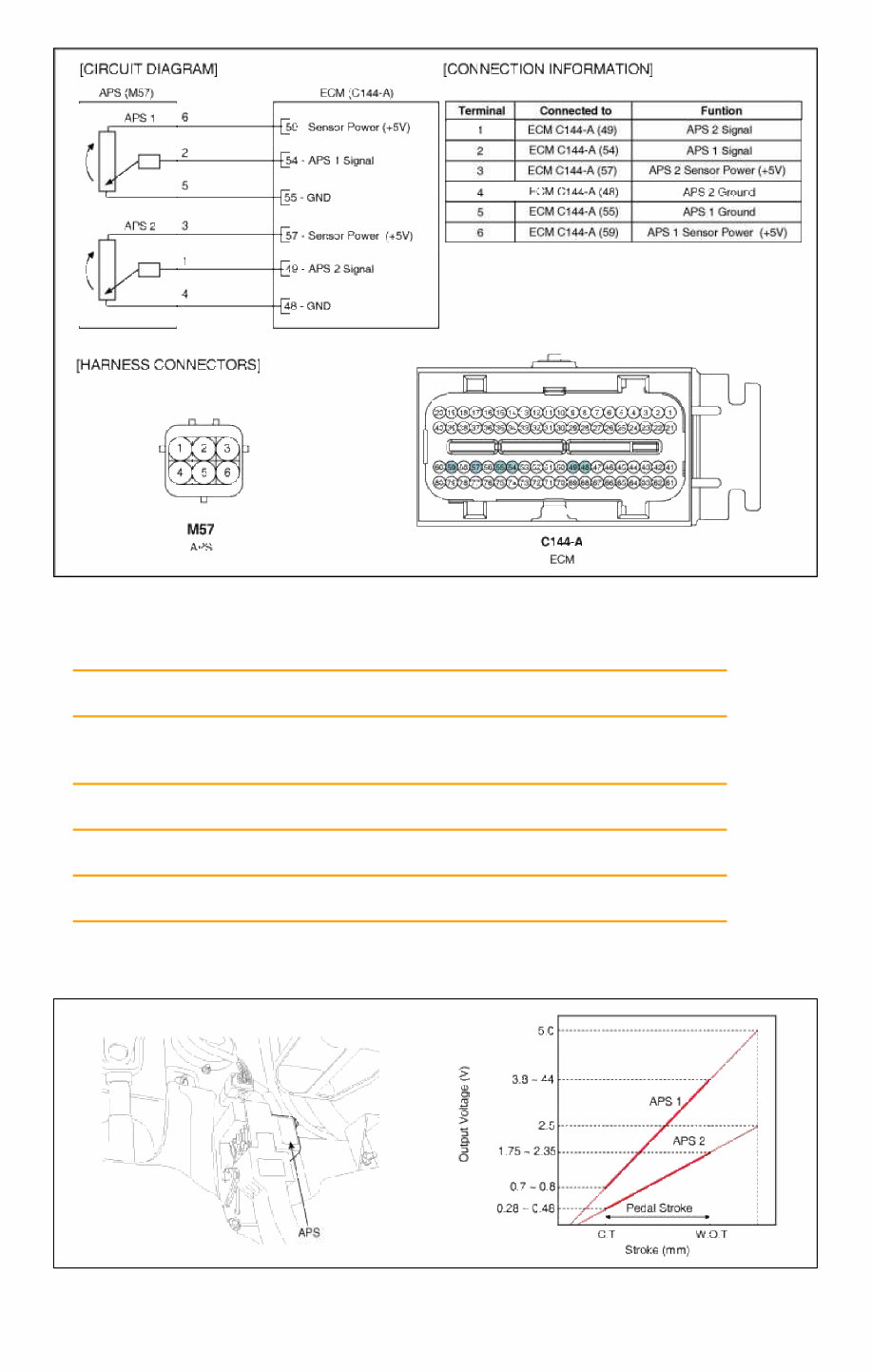
COMPONENT INSPECTION 1. Connect a scan tool to the Diagnosis Link Connector (DLC). 2. Start engine and check output voltages of APS 1 and 2 at C.T and W.O.T. Specification: Refer to SPECIFICATION. 3. Turn ignition switch OFF and disconnect the scantool from the DLC. 4. Disconnect APS connector and measure resistance between APS terminals 5 and 6 (APS 1). Specification: Refer to SPECIFICATION. 5. Disconnect APS connector and measure resistance between APS terminals 3 and 4 (APS 2). Specification: Refer to SPECIFICATION. INSPECTION FUNCTION AND OPERATION PRINCIPLE Accelerator Position Sensor (APS) is installed on the accelerator pedal module and detects the rotation angle of the Page 2 of 4
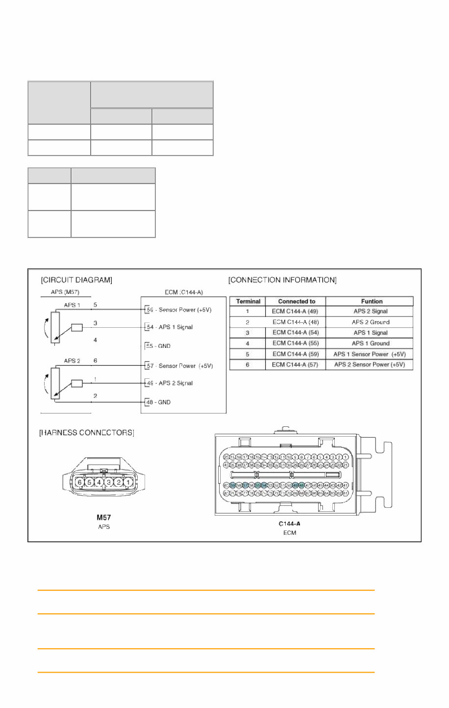
accelerator pedal. The APS is one of the most important sensors in engine control system, so it consists of the two sensors which adapt individual sensor power and ground line. The second sensor monitors the first sensor and its output voltage is half of the first one. If the ratio of the sensor 1 and 2 is out of the range (approximately 1/2), the diagnostic system judges that it is abnormal. SPECIFICATION Pedal Position Output Voltage (V) [Vref = 5.0V] APS1 APS2 C.T 0.7 ~ 0.8 0.28 ~ 0.48 W.O.T 3.8 ~ 4.4 1.75 ~ 2.35 Item Sensor Resistance APS1 0.7 ~ 1.3kΩ at 20°C (68°F) APS2 1.4 ~ 2.6kΩ at 20°C (68°F) SCHEMATIC DIAGRAM COMPONENT INSPECTION 1. Connect a scan tool to the Diagnosis Link Connector (DLC). 2. Start engine and check output voltages of APS 1 and 2 at C.T and W.O.T. Specification: Refer to SPECIFICATION. 3. Turn ignition switch OFF and disconnect the scantool from the DLC. 4. Disconnect APS connector and measure resistance between APS terminals 5 and 6 (APS 1). Specification: Refer to SPECIFICATION. Page 3 of 4
5. Disconnect APS connector and measure resistance between APS terminals 3 and 4 (APS 2). Specification: Refer to SPECIFICATION. Page 4 of 4
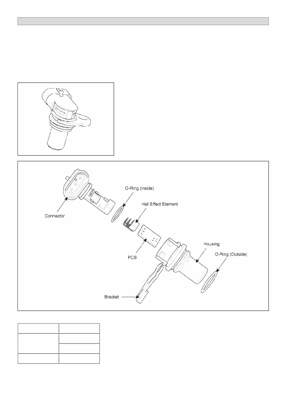
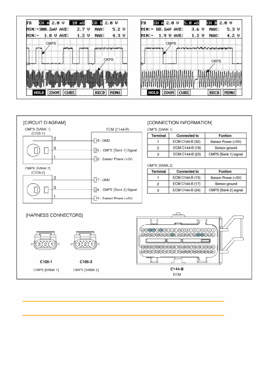
SORENTO(BL) >2008 > G 3.8 DOHC > Fuel System INSPECTION FUNCTION AND OPERATION PRINCIPLE Camshaft Position Sensor (CMPS) is a hall sensor and detects the camshaft position by using a hall element. It is related with Crankshaft Position Sensor (CKPS) and detects the piston position of each cylinder which the CKPS can't detect. The two CMPS are installed on engine head cover of bank 1 and 2 and uses a target wheel installed on the camshaft. This sensor has a hall-effect IC which output voltage changes when magnetic field is made on the IC with current flow. So the sequential injection of the 6 cylinders is impossible without CMPS signal. SPECIFICATION Item Specification Output Voltage (V) High : 5.0V Low : 0 ~ 0.7V Air Gap (mm) 0.5 ~ 1.5 WAVEFORM Page 1 of 2
SCHEMATIC DIAGRAM COMPONENT INSPECTION 1. Check signal waveform of CMPS and CKPS using a scantool. Specification: Refer to "WAVE FORM" Page 2 of 2
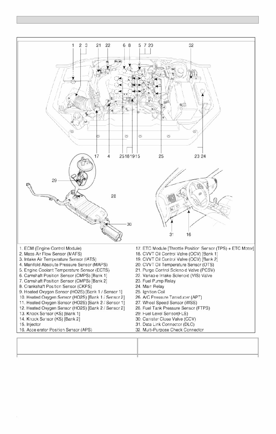
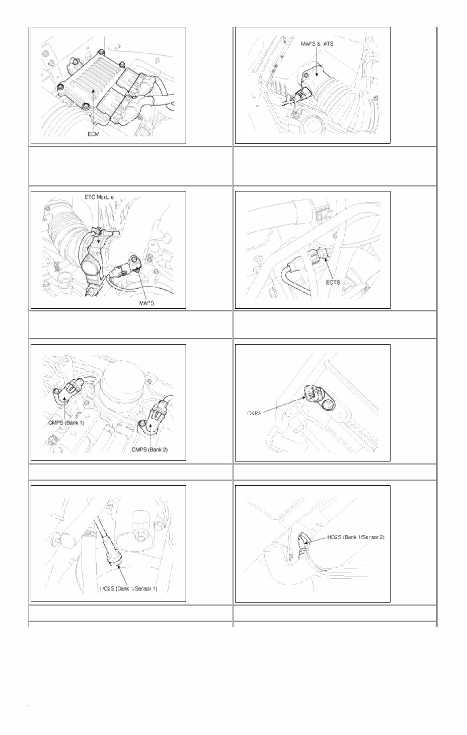
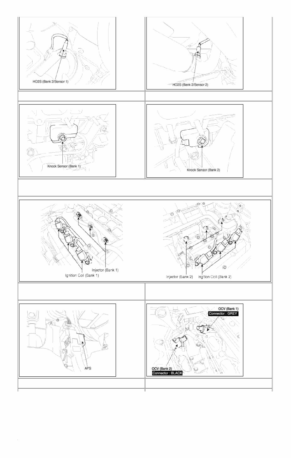
SORENTO(BL) >2008 > G 3.8 DOHC > Fuel System COMPONENT LOCATION 1. ECM (Engine Control Module) 2. Mass Air Flow Sensor (MAFS) 3. Intake Air Temperature Sensor (IATS) Page 1 of 5
Title: KIA SORENTO 3.8L 2008 Full Service Repair Manual
The KIA SORENTO 3.8L 2008 Full Service Repair Manual is a comprehensive guide that provides detailed instructions and diagrams for servicing and repairing the KIA SORENTO 3.8L model from the year 2008. Whether you are a DIY enthusiast or a professional mechanic, this manual provides all the necessary information to successfully carry out repairs and maintenance on your vehicle.
This manual covers a wide range of topics, including:
Engine
Transmission
Brakes
Suspension
Electrical system
Heating and air conditioning
With this repair manual, you can easily diagnose and fix any issues with your KIA SORENTO 3.8L 2008 model. The step-by-step instructions, accompanied by detailed illustrations and diagrams, make the repair process clear and accessible to both novice and experienced technicians.
Whether you need to replace a faulty component, perform regular maintenance tasks, or simply understand the inner workings of your vehicle, the KIA SORENTO 3.8L 2008 Full Service Repair Manual is an indispensable tool.
Invest in this manual today and keep your KIA SORENTO 3.8L 2008 running smoothly for years to come!