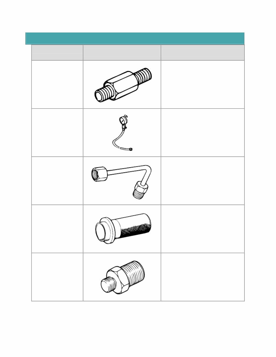
SPECIAL SERVICE TOOLS Tool (Number and name) Illustration Use 09452-21000 Oil pressure gauge adapter Measurement of the oil pressure (use with 09452-21500, 09452-21600, 09452- 32300) 09452-21500 Oil pressure gauge Measurement of the oil pressure (use with 09452-21000, 09452-21600, 09452- 32300) 09452-21600 Oil pressure gauge adapter Measurement of the oil pressure (use with 09452-21000, 09452-21500, 09452- 32300) 09452-32100 Oil seal installer Installation of the oil pump oil seal 09452-32300 Oil pressure gauge adapter Measurement of the oil pressure (use with 09452-21000, 09452-21500, 09452- 21600)
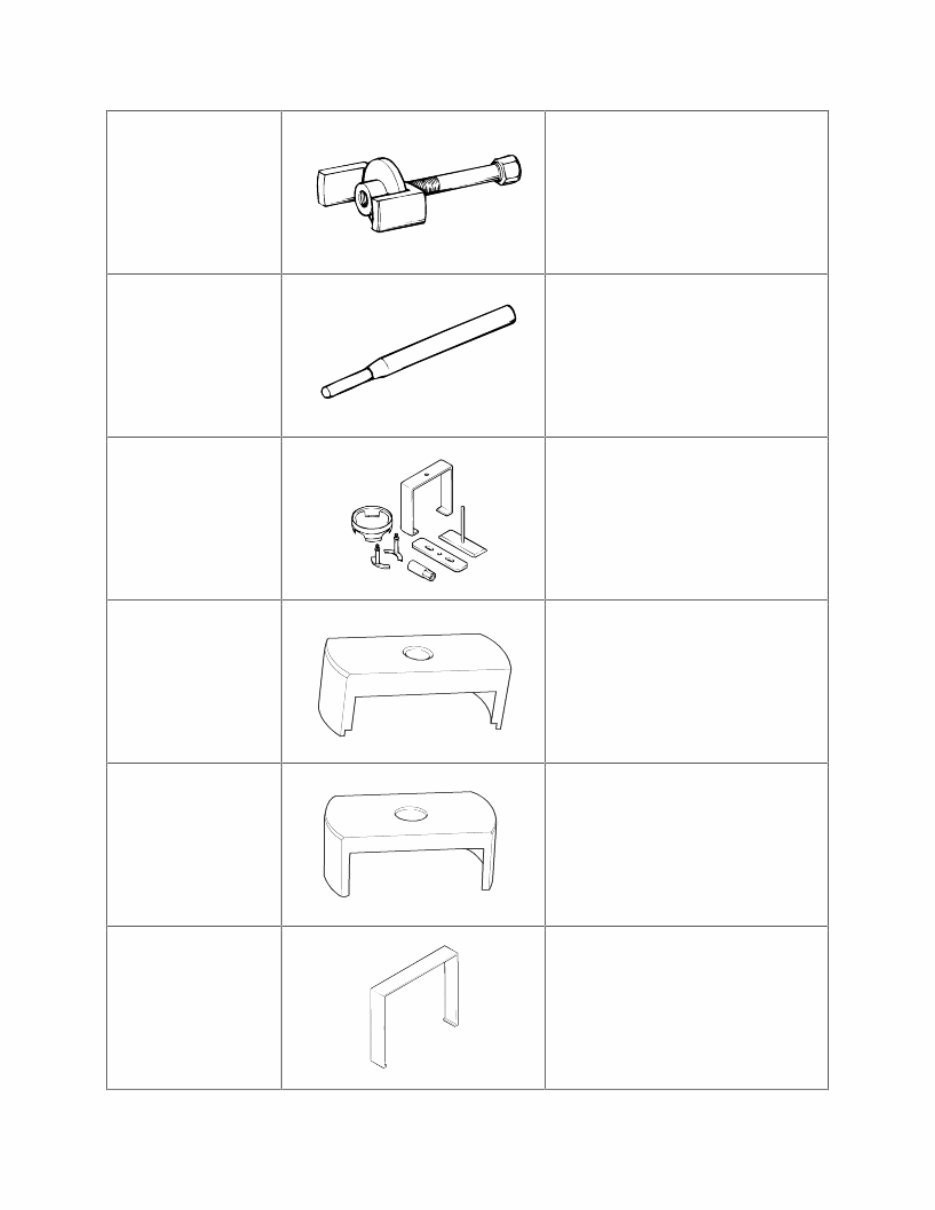
09453-32100 Piston spring compressor Removal of the clutch piston 09414-11000 Lock pin extractor Removal of the pin in the lock pawl rod 09455-38000 Spring compressor Removal of the overdrive return spring Removal of the forward clutch spring Removal of the direct clutch spring 09454-38000 Second brake spring compressor Removal of second brake spring 09454-38100 First & reverse brake spring compressor Removal of first & reverse brake spring 09454-38200 Reverse brake piston remover Removal of reverse brake piston
09454-38300 Reaction sleeve remover Removal of reaction sleeve
SPECIFICATION TIGHTENING TORQUE Item N·m Kg·cm Ib·ft Transmission housing to case (10mm) Transmission housing to case (12mm) Extension housing to T/M case O/D case to T/M case Oil pump to T/M case Oil pump body to stator shaft Valve body Oil strainer Oil pan Speed sensor Speedometer driven gear lock plate Union Transaxle range switch bolt Transaxle range switch nut Control shaft lever Shift knob screw Shift lever bracket 35 58 37 26 22 10 10 10 7.5 7.5 16 30 13 7 16 - 23 2 - 3 8 - 11 350 580 370 260 220 100 100 100 75 75 160 300 130 70 160 - 230 20 - 30 80 - 110 25 42 27 19 16 7 7 7 5 5 11 22 9 5 11 - 16 1 - 2 6 - 8
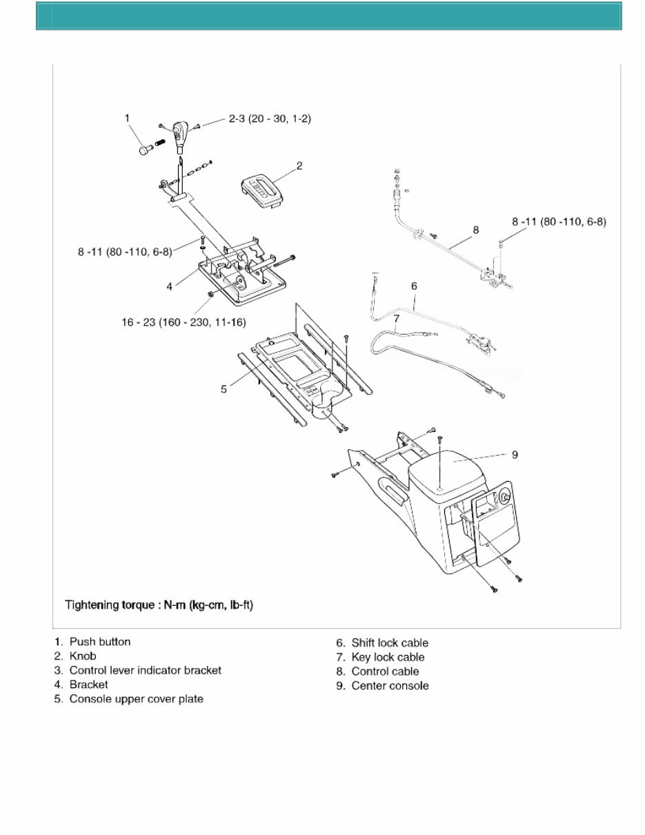
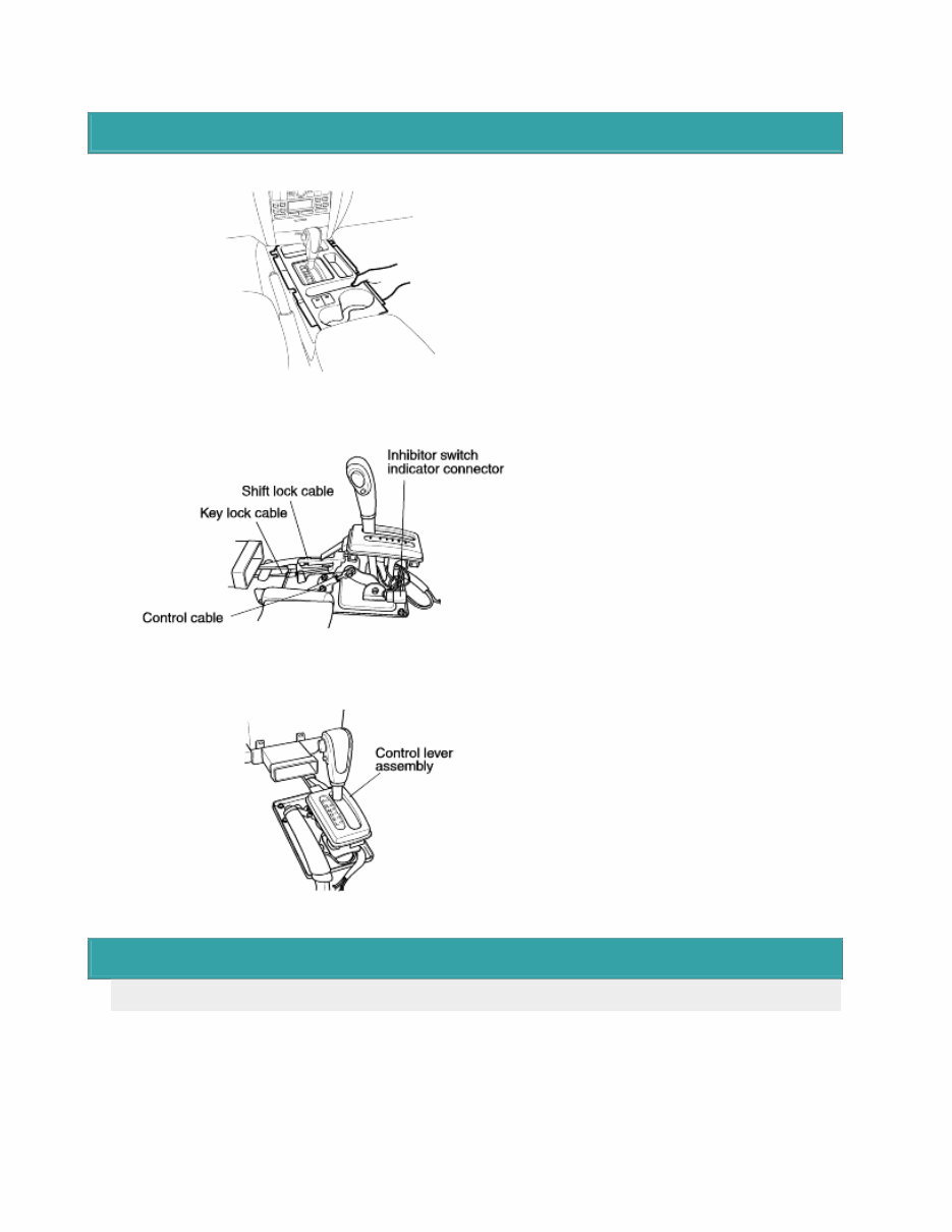
COMPONENTS
REMOVAL 1. Remove the console upper cover plate. 2. Remove the center console assembly. 3. Remove the control cable, the shift lock cable and key lock cable. 4. Disconnect the inhibitor switch indicator connector. 5. Remove the control lever assembly. 6. Remove the control lever bracket. SHIFT LOCK DEVICE INSTALLATION INSTRUCTIONS INSPECTION a. Check the detent place for wear. b. Check the bushing for wear or damage. c. Check the spring for damage or deterioration. d. Check the pin at the end of the rod assembly for wear.
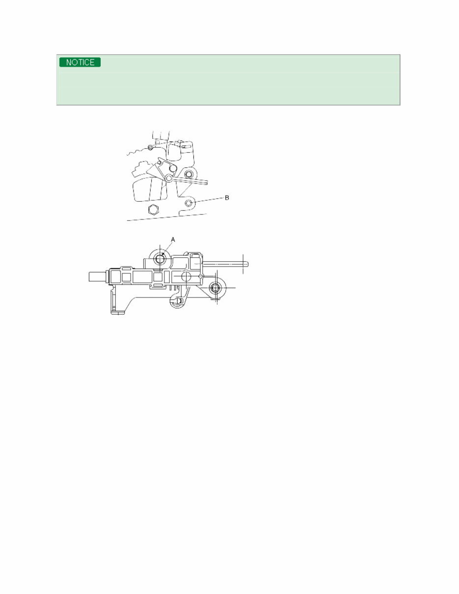
When servicing the shift lock device, follow the service instructions and procedures described below in order to operateit normally. 1. Procedure to install the lock cam. a. Make sure to move shift lever to position "P" to set key lock cam and p-lock as figure. 2. Procedure for adjusting "P" shift lock and key lock cable. (1) Check that lock cam is located in position. (2) Install shift lock cable in position as figure. (3) Temporarily install shift lock cable to A/T lever assembly as shown in figure. Securely insert cable end into fixing pin of cam. (4) After checking that a portion of cable end touches cable fixing pin of P-lock cam, fix shift lock cable to A/T lever. 3. Checking that procedure for installing the shift lock is correct. (1) When the brake pedal is not depressed, push button of the shift lever at "P" position cannot be operated. (Shift lever cannotbe shifted at the other positions from "P"). Push button can be operated at the other positions except "P". (2) When brake pedal stroke is 30 mm (with shift lever at "P" position), push button should be operated without catching and shift levercan be shifted smoothly to other from "P". (3) When brake pedal is not depressed, shift lever should be shifted smoothly to "P" position from other positions. (4) Brake pedal must be operated smoothly without catching at all positions. (5) If shift lever is shifted to "P" position, ignition key must be turned to "LOCK" position smoothly.
(6) Adjust nut "A" and bolt "B" if necessary.
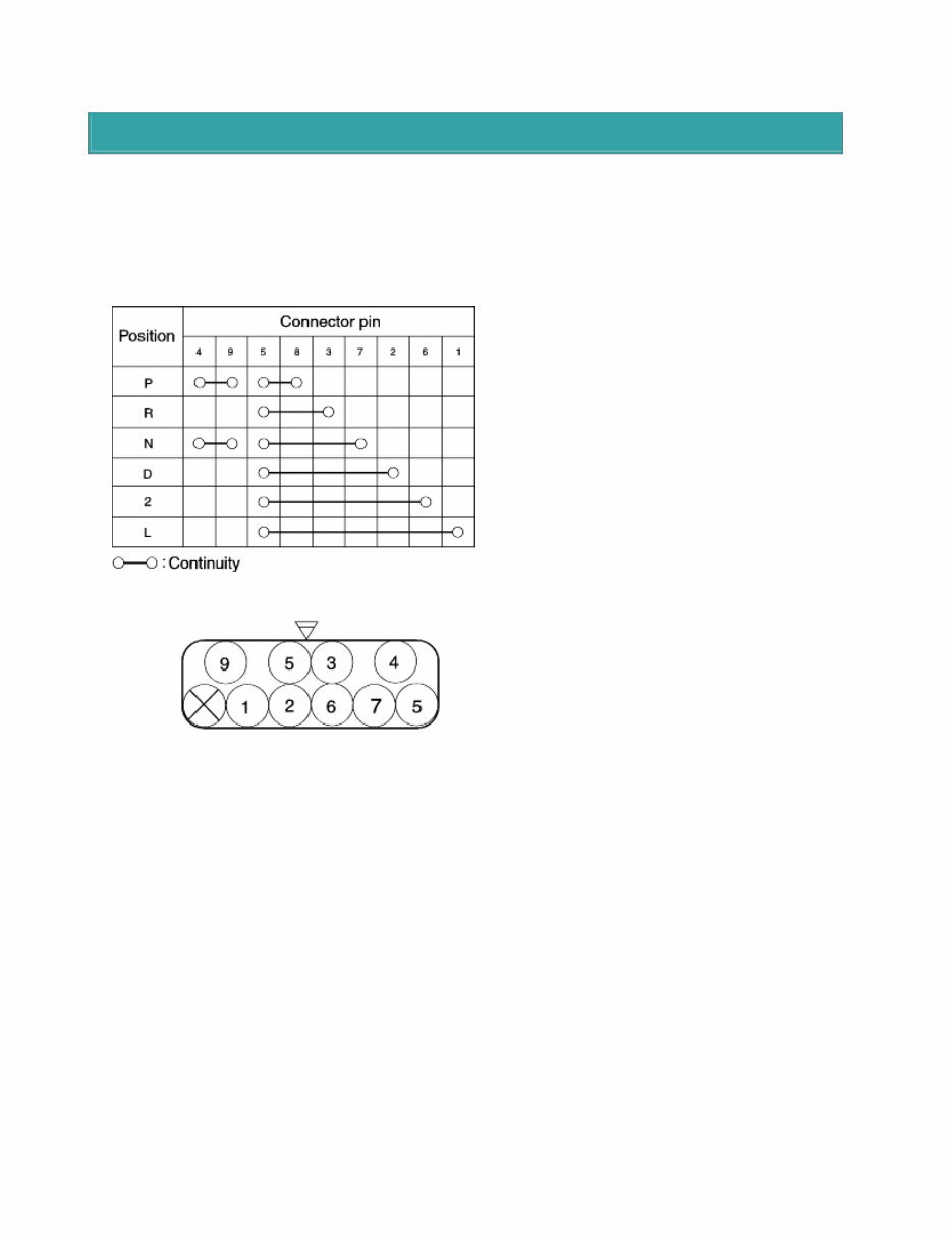
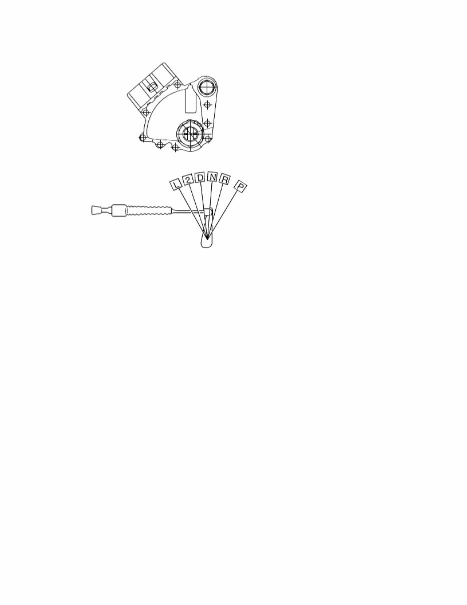
TRANSAXLE RANGE SWITCH 1. Operating inspection (1) Check that the starter turns with the ignition switch at START position and the selector in the "P" and "N range only. (2) Check that the back-up (reverse) lights illuminate when shifted to the "R" range with the ignition switch in the ON position. (3) Check the transaxle range switch if it is not working properly. 1. Adjustment (1) Shift the selector lever to the "N" range. (2) Loosen the transaxle range switch mounting bolts. (3) Disconnect the transaxle range switch connector. (4) Check the continuity of the terminals using ohmmeter. (5) Adjust the switch to the point where there is continuity between the terminals.
The Kia Sorento 2008 Service Repair Workshop Manual is the ultimate guide for anyone looking to maintain or repair their Kia Sorento model from the year 2008. This comprehensive manual provides detailed step-by-step instructions and illustrations, making it easy to follow and understand.
Kia Sorento 2008 LX model
Kia Sorento 2008 EX model
Kia Sorento 2008 Limited model
Whether you are a professional mechanic or a Kia Sorento owner who prefers the DIY approach, this workshop manual is perfect for you. It covers a wide range of topics, including engine maintenance, transmission repairs, electrical system troubleshooting, and more.
With the Kia Sorento 2008 Service Repair Workshop Manual, you'll have all the information you need to keep your vehicle running smoothly and efficiently. No more guesswork or expensive trips to the dealership. Everything you need to know is right at your fingertips.
Invest in this manual today and take control of your Kia Sorento's maintenance needs. Keep your vehicle in top-notch condition and save money in the long run. Order now and get the peace of mind that comes with having a comprehensive repair manual by your side.