Emissions Control System GENERAL CRANKCASE EMISSION CONTROL SYS- TEM POSITIVE CRANKCASE VENTILATION (PCV) VALVE EVAPORATIVE EMISSION CONTROL SYS- TEM CANISTER PURGE CONTROL SOLENOID VALVE (PCSV) FUEL TANK AIR FILTER FUEL FILLER CAP EXHAUST EMISSION CONTROL SYSTEM CONTINUOUS VARIABLE VALVE TIMING (CVVT)
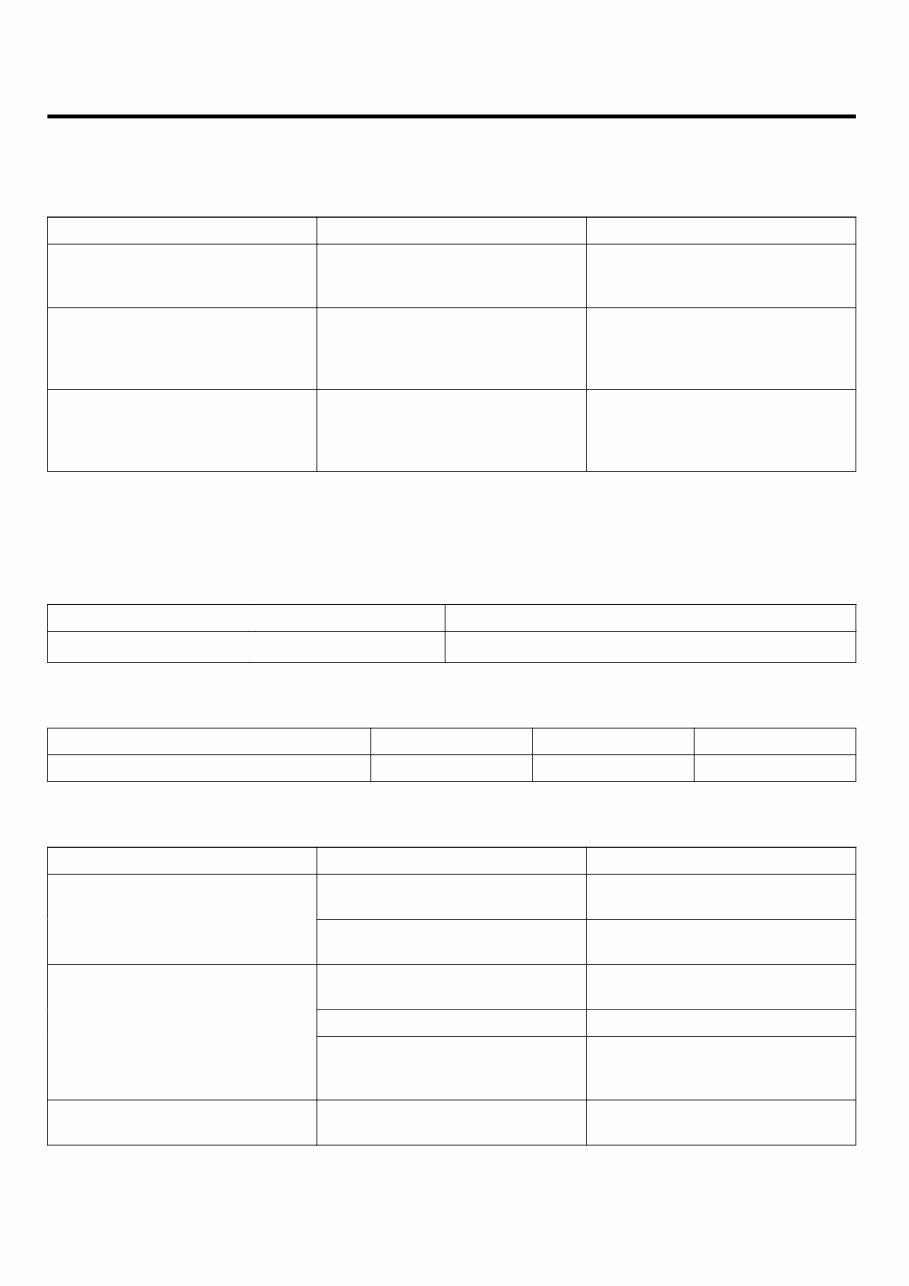
EC -2 EMISSIONS CONTROL SYSTEM GENERAL DESCRIPTION ED0CA305 Components Function Remarks Crankcase Emission System - Positive Crankcase Ventilation (PCV) valve HC reduction Variable flow rate type Evaporative Emission System - Evaporative emission canister - Purge Control Solenoid Valve (PCSV) HC reduction HC reduction Duty control solenoid valve Exhaust Emission System - MFI system (air-fuel mixture control device) - Three-way catalytic converter CO, HC, NOx reduction CO, HC, NOx reduction Heated oxygen sensor feedback type Monolithic type SPECIFICATIONS EF2996DD PURGE CONTROL SOLENOID VALVE (PCSV) ▷ Specification Item Specification Coil Resistance (Ω ) 14.0 ~ 18.0 Ω [20℃ (68℉)] TIGHTENING TORQUES E34D5DE1 Item N·m kgf·m lbf·m Positive Crankcase Ventilation Valve 8.0 ~ 12.0 0.8 ~ 1.2 6.0 ~ 8.0 TROUBLESHOOTING E2236ADE Symptom Suspect area Remedy Vacuum hose disconnected or damaged Repair or replace Engine will not start or hard to start Malfunction of the Purge Control Solenoid Valve Repair or replace Vacuum hose disconnected or damaged Repair or replace Malfunction of the PCV valve Replace Rough idle or engine stalls Malfunction of the evaporative emission canister purge system Check the system; if there is a problem, check related components parts Excessive oil consumption Positive crankcase ventilation line clogged Check positive crankcase ventilation system
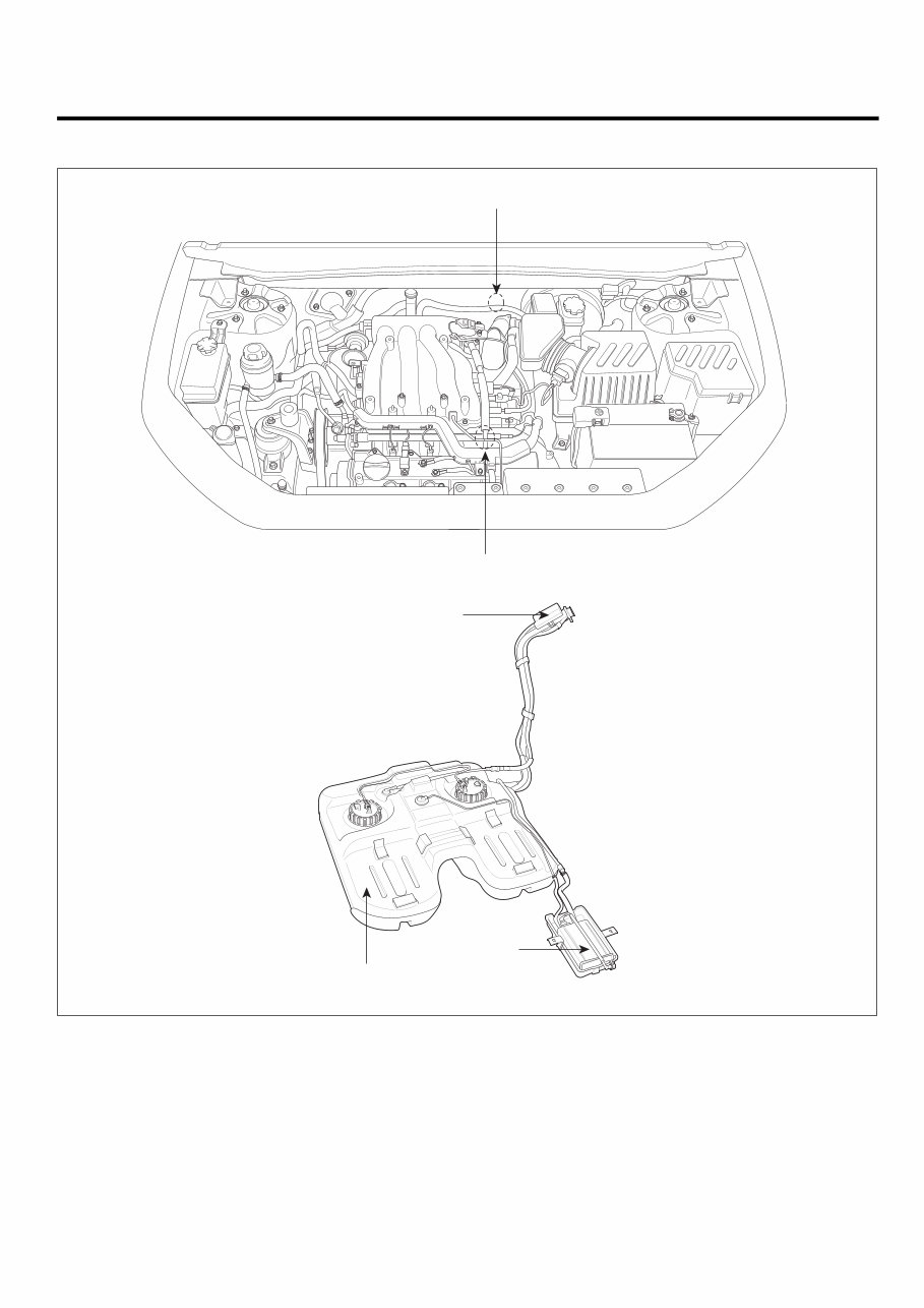
GENERAL EC -3 COMPONENT LOCATION EB6479B1 1. Purge Control Solenoid Valve (PCSV) 2. PCV Vlave 3. Canister 4. Catalytic Converter (Bank 1) 5. Catalytic Converter (Bank 2) 6. Fuel Tank Air Filter 1 2 6 Fuel Tank 3 SCMEC6001L
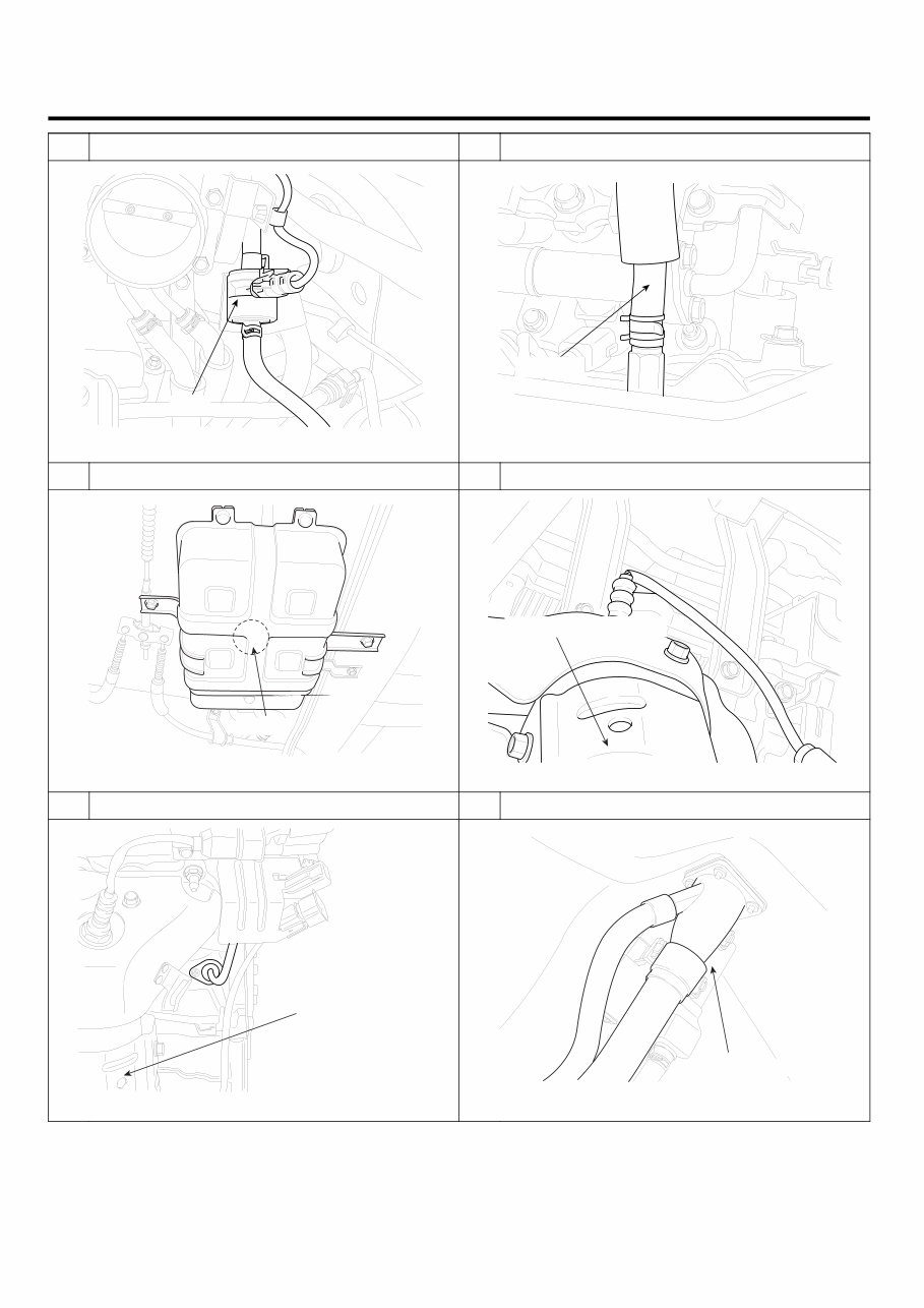
EC -4 EMISSIONS CONTROL SYSTEM 1 Purge Control Solenoid Valve (PCSV) 2 Positive Crankcase Ventilation (PCV) Valve PCSV LGLG001L PCV Valve LELG001G 3 Canister 4 Catalytic Converter (Bank 1) Canister SCMEC6002L Catalytic Converter (Bank 1) LELG001H 5 Catalytic Converter (Bank 2) 6 Fuel Tank Air Filtter Catalytic Converter (Bank 2) LELG001I Fuel Tank Air Filter SCMEC6003L
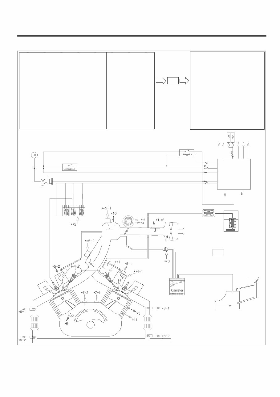
GENERAL EC -5 SCHEMATIC DIAGRAM E6C3F98F *1. Mass Air Flow Sensor (MAFS) *2. Intake Air Temperature Sensor (IATS) *3. Engine Coolant Tmeperature Sensor (ECTS) *4. Throttle Position Sensor (TPS) *5-1. Camshaft Position Sensor (CMPS) [BANK1] *5-2. Camshaft Position Sensor (CMPS) [BANK2] *6. Crankshaft Position Sensor (CKPS) *7-1. Knock Sensor (KS) #1 *7-2. Knock Sensor (KS) #2 *8-1. Heated Oxygen Sensor (HO2S) [B1/S1] *8-2. Heated Oxygen Sensor (HO2S) [B1/S2] *9-1. Heated Oxygen Sensor (HO2S) [B2/S1] *9-2. Heated Oxygen Sensor (HO2S) [B2/S2] *10. Manifold Absolute Pressure Sensor (MAPS) *11. CVVT Oil Temperature Sensor (OTS) . Ignition Switch . Battery Voltage . Vehicle Speed Signal . Coolant Load Signal . "PNP" Switch (A/T only) . Fuel Pump Relay Signal PCM **1. Fuel Injector **2. Ignition Coil **3. Purge Control Solenoid Valve (PCSV) **4-1. CVVT Oil control valve (OCV) [BANK1] **4-2. CVVT Oil control valve (OCV) [BANK2] **5-1. Variable Intake Manifold Solenoid (VIS) Valve [Surge Tank] **5-2. Variable Intake Manifold Solenoid (VIS) Valve [Intake Manifold] **6. ETC Motor . Fuel Pump Control . Main Relay . Cooler Relay . Ignition Timing Control . Disagnosis PCM Fuel Filter OUTPUT INPUT Fuel Pump Fuel Tank Air Cleaner Fuel Tank Air Filter Fuel Tank MCC MCC Spark Plug Ignition Switch Main Relay Battery Fuel Pump Relay LELG001K
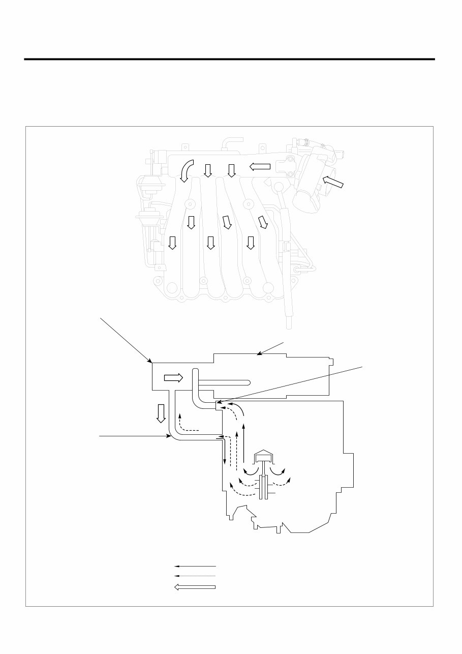
EC -6 EMISSIONS CONTROL SYSTEM CRANKCASE EMISSION CONTROL SYSTEM COMPONENTS EAB892E6 During Low Load Operation During High Load Operation Fresh Air Air intake hose Breather hose PCV Valve Surge Tank LELG001L
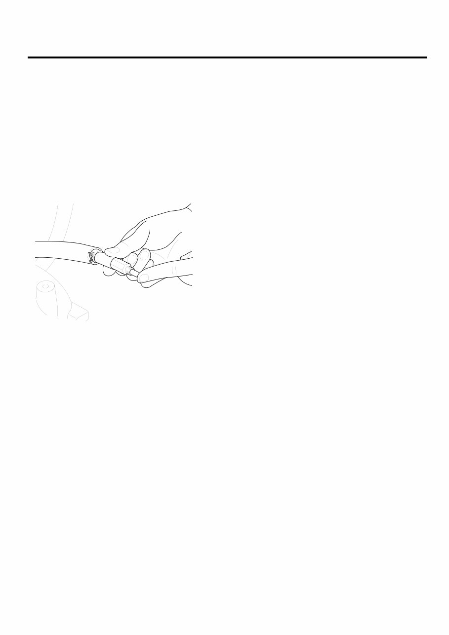
CRANKCASE EMISSION CONTROL SYSTEM EC -7 INSPECTION EE69E0AE 1. Disconnect the ventilation hose from the positive crankcase ventilation (PCV) valve. Remove the PCV valve from the rocker cover and reconnect it to the ventilation hose. 2. Run the engine at idle and put a finger on the open end of the PCV valve and make sure that intake man- ifold vacuum can be felt. NOTE The plunger inside the PCV valve will move back and forth. SCMEC6004L
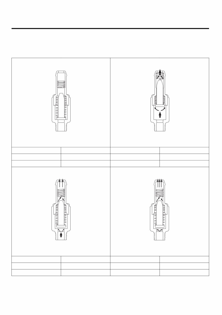
EC -8 EMISSIONS CONTROL SYSTEM POSITIVE CRANKCASE VENTILATION (PCV) VALVE OPERATION EBB0DAB9 Intake manifold side (No vacuum) Rocker cover side BEGE001S Intake manifold side (High vacuum) Rocker cover side BEGE001T Engine condition Not running Engine condition Idling or decelerating PCV valve Not operating PCV valve Fully operating Vacuum passage Restricted Vacuum passage Small Intake manifold side (Moderate vacuum) Rocker cover side BEGE001U Intake manifold side (Low vacuum) Rocker cover side BEGE001V Engine condition Normal operation Engine condition Accelerating and high load PCV valve Properly operating PCV valve Slightly operating Vacuum passage Large Vacuum passage Very large
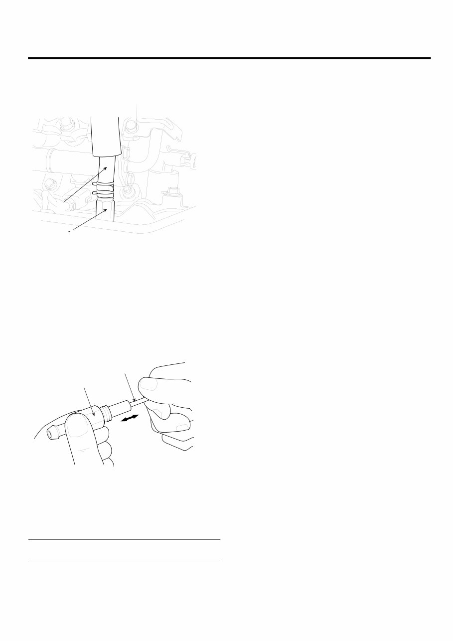
CRANKCASE EMISSION CONTROL SYSTEM EC -9 REMOVAL EB3C969B 1. Disconnect the vacuum hose (A) and remove the PCV valve (B). A B SCMEC6005L INSPECTION EEDF42DC 1. Remove the PCV valve. 2. Insert a thin stick(A) into the PCV valve(B) from the threaded side to check that the plunger moves. 3. If the plunger does not move, the PCV valve is clogged. Clean it or replace. B A EERF600J INSTALLATION E7FA321E Install the PCV valve and tighten to the specified torque. PCV Valve installation : 7.8 ~ 11.8 N·m (0.8 ~ 1.2 kgf·m, 5.8 ~ 8.7lbf·ft)
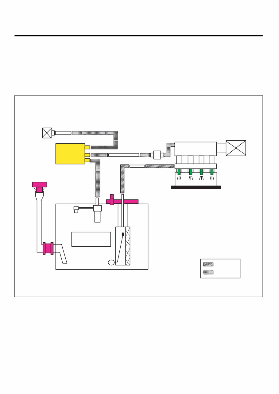
EC -10 EMISSIONS CONTROL SYSTEM EVAPORATIVE EMISSION CONTROL SYSTEM DESCRIPTION E4D6C1B7 Evaporative Emission Control System prevents fuel va- por stored in fuel tank from vaporizing into the atmos- phere. When the fuel evaporates in the fuel tank, the vapor passes through vent hoses or tubes to the canister filled with charcoal and the canister temporarily holds the vapor in the charcoal. If ECM determines to draw the gathered vapor into the combustion chambers during certain oper- ating conditions, it will use vacuum in intake manifold to move it. Engine Fuel Tank Fuel Pump Fuel Filler Cap Canister Air Cleaner Fuel Rail & Injector B A Filler Pipe Joint Hose PCSV Fuel Tank Air Filter Fuel Feed Line EVAP Tube A: 2-Way & Cut Valve B: ORVR Valve LEKG033A
The 2012 Kia Sorento (XM) Service & Repair Manual delivers precise technical information for both powertrain options—the muscular 3.5L Lambda II MPi V6 and the torque-rich 2.2L R II CRDi diesel. This factory-developed resource contains detailed specifications and step-by-step procedures for maintaining every major system on this second-generation platform.
This manual provides systematic troubleshooting sequences, component specifications, and illustrated repair procedures organized by vehicle system. You'll find exact valve clearances, torque patterns, fluid capacities, and critical adjustment specifications for everything from the powertrain to the electronically-controlled AWD system.
Whether you're performing basic maintenance, rebuilding that CRDi high-pressure pump, or tackling complex drivetrain issues, this manual gives you factory-correct specifications instead of forum guesswork. Save yourself the headache of multiple repair attempts and fix it right the first time.
Printable: Yes Language: English Compatibility: Pretty much any electronic device, incl. PC & Mac computers, Android and Apple smartphones & tablet, etc. Requirements: Adobe Reader (free)

 Service & Repair Manual")