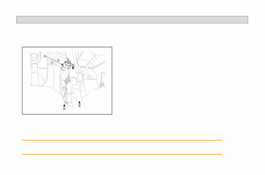
SORENTO(BL) >2008 > G 3.8 DOHC > Fuel System REMOVAL 1. Turn ignition switch off and disconnect the battery (-) cable from the battery. 2. Disconnect the accelerator position sensor connector (A). 3. Unfasten the mounting bolt/nuts (B) and remove the accelerator pedal from the vehicle. INSTALLATION 1. Install the accelerator pedal in according to the reverse order of "REMOVAL" procedure. Accelerator pedal mounting nuts: 7.8 ~ 11.8N·m (0.8 ~ 1.2kgf·m, 5.8 ~ 8.7lbf·ft) Page 1 of 1
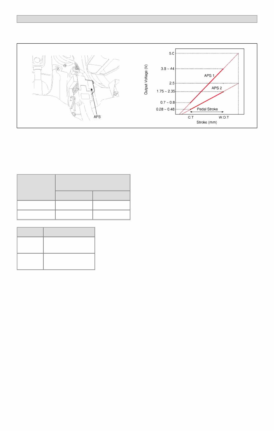
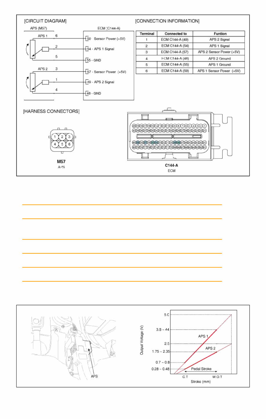
SORENTO(BL) >2008 > G 3.8 DOHC > Fuel System INSPECTION FUNCTION AND OPERATION PRINCIPLE Accelerator Position Sensor (APS) is installed on the accelerator pedal module and detects the rotation angle of the accelerator pedal. The APS is one of the most important sensors in engine control system, so it consists of the two sensors which adapt individual sensor power and ground line. The second sensor monitors the first sensor and its output voltage is half of the first one. If the ratio of the sensor 1 and 2 is out of the range (approximately 1/2), the diagnostic system judges that it is abnormal. SPECIFICATION Pedal Position Output Voltage (V) [Vref = 5.0V] APS1 APS2 C.T 0.7 ~ 0.8 0.28 ~ 0.48 W.O.T 3.8 ~ 4.4 1.75 ~ 2.35 Item Sensor Resistance APS1 0.7 ~ 1.3kΩ at 20°C (68°F) APS2 1.4 ~ 2.6kΩ at 20°C (68°F) SCHEMATIC DIAGRAM Page 1 of 4
COMPONENT INSPECTION 1. Connect a scan tool to the Diagnosis Link Connector (DLC). 2. Start engine and check output voltages of APS 1 and 2 at C.T and W.O.T. Specification: Refer to SPECIFICATION. 3. Turn ignition switch OFF and disconnect the scantool from the DLC. 4. Disconnect APS connector and measure resistance between APS terminals 5 and 6 (APS 1). Specification: Refer to SPECIFICATION. 5. Disconnect APS connector and measure resistance between APS terminals 3 and 4 (APS 2). Specification: Refer to SPECIFICATION. INSPECTION FUNCTION AND OPERATION PRINCIPLE Accelerator Position Sensor (APS) is installed on the accelerator pedal module and detects the rotation angle of the Page 2 of 4
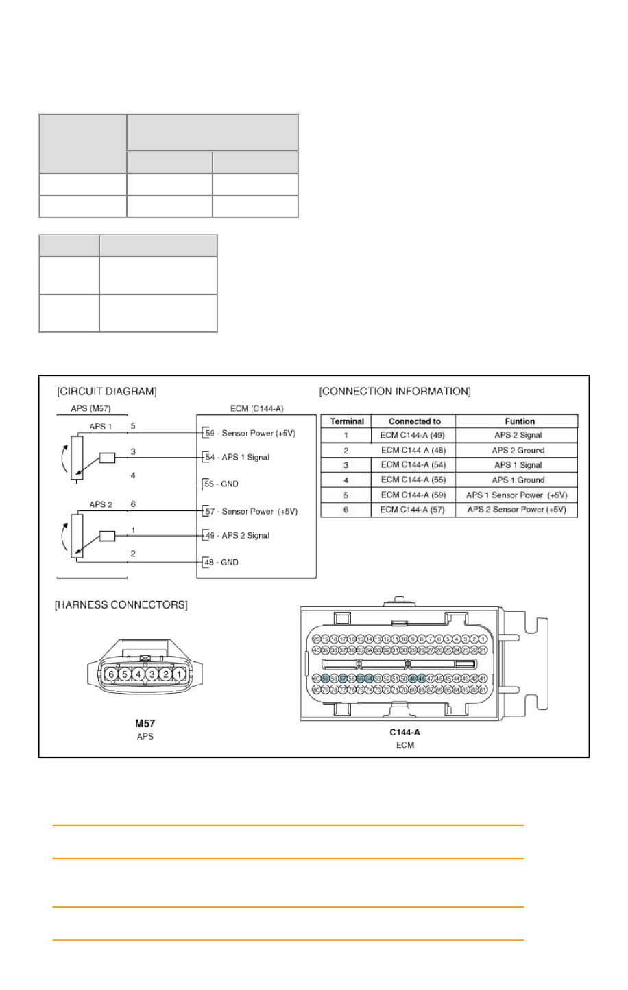
accelerator pedal. The APS is one of the most important sensors in engine control system, so it consists of the two sensors which adapt individual sensor power and ground line. The second sensor monitors the first sensor and its output voltage is half of the first one. If the ratio of the sensor 1 and 2 is out of the range (approximately 1/2), the diagnostic system judges that it is abnormal. SPECIFICATION Pedal Position Output Voltage (V) [Vref = 5.0V] APS1 APS2 C.T 0.7 ~ 0.8 0.28 ~ 0.48 W.O.T 3.8 ~ 4.4 1.75 ~ 2.35 Item Sensor Resistance APS1 0.7 ~ 1.3kΩ at 20°C (68°F) APS2 1.4 ~ 2.6kΩ at 20°C (68°F) SCHEMATIC DIAGRAM COMPONENT INSPECTION 1. Connect a scan tool to the Diagnosis Link Connector (DLC). 2. Start engine and check output voltages of APS 1 and 2 at C.T and W.O.T. Specification: Refer to SPECIFICATION. 3. Turn ignition switch OFF and disconnect the scantool from the DLC. 4. Disconnect APS connector and measure resistance between APS terminals 5 and 6 (APS 1). Specification: Refer to SPECIFICATION. Page 3 of 4
5. Disconnect APS connector and measure resistance between APS terminals 3 and 4 (APS 2). Specification: Refer to SPECIFICATION. Page 4 of 4
The KIA Sorento Complete Workshop Service Repair Manual is a comprehensive guide designed to assist owners with the maintenance and repair of their vehicles. This manual is specifically tailored for the KIA Sorento models from 2007 to 2009.
Whether you are a professional mechanic or a KIA Sorento owner who prefers to handle repairs on your own, this workshop manual is an invaluable resource. It provides detailed instructions, diagrams, and illustrations to guide you through every aspect of service and repair for your vehicle.
With this workshop manual, you can confidently tackle a wide range of tasks, from routine maintenance procedures to complex engine repairs. Some of the key features of this manual include:
Step-by-step instructions for various repair procedures
Detailed diagrams and illustrations to aid understanding
Diagnostic information for troubleshooting various systems
Safety precautions to ensure proper and safe repairs
Specifications and technical data for accurate repairs
Whether you need to perform routine oil changes, replace brakes, or diagnose electrical issues, the KIA Sorento Complete Workshop Service Repair Manual has you covered. It is an indispensable tool for any Sorento owner or mechanic.