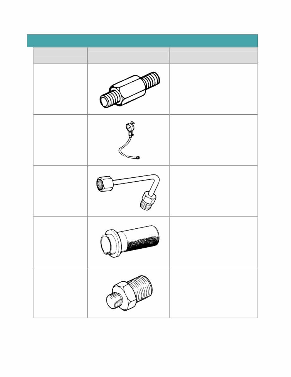
SPECIAL SERVICE TOOLS Tool (Number and name) Illustration Use 09452-21000 Oil pressure gauge adapter Measurement of the oil pressure (use with 09452-21500, 09452-21600, 09452- 32300) 09452-21500 Oil pressure gauge Measurement of the oil pressure (use with 09452-21000, 09452-21600, 09452- 32300) 09452-21600 Oil pressure gauge adapter Measurement of the oil pressure (use with 09452-21000, 09452-21500, 09452- 32300) 09452-32100 Oil seal installer Installation of the oil pump oil seal 09452-32300 Oil pressure gauge adapter Measurement of the oil pressure (use with 09452-21000, 09452-21500, 09452- 21600)
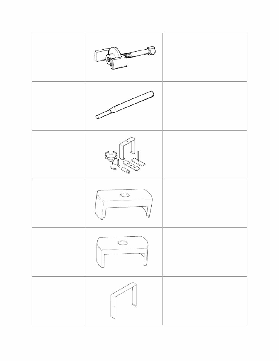
09453-32100 Piston spring compressor Removal of the clutch piston 09414-11000 Lock pin extractor Removal of the pin in the lock pawl rod 09455-38000 Spring compressor Removal of the overdrive return spring Removal of the forward clutch spring Removal of the direct clutch spring 09454-38000 Second brake spring compressor Removal of second brake spring 09454-38100 First & reverse brake spring compressor Removal of first & reverse brake spring 09454-38200 Reverse brake piston remover Removal of reverse brake piston
09454-38300 Reaction sleeve remover Removal of reaction sleeve
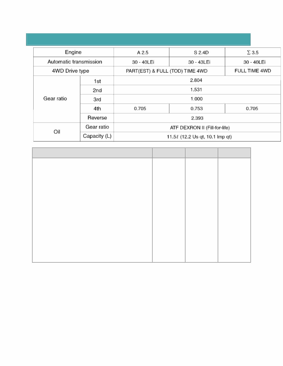
SPECIFICATION TIGHTENING TORQUE Item N·m Kg·cm Ib·ft Transmission housing to case (10mm) Transmission housing to case (12mm) Extension housing to T/M case O/D case to T/M case Oil pump to T/M case Oil pump body to stator shaft Valve body Oil strainer Oil pan Speed sensor Speedometer driven gear lock plate Union Transaxle range switch bolt Transaxle range switch nut Control shaft lever Shift knob screw Shift lever bracket 35 58 37 26 22 10 10 10 7.5 7.5 16 30 13 7 16 - 23 2 - 3 8 - 11 350 580 370 260 220 100 100 100 75 75 160 300 130 70 160 - 230 20 - 30 80 - 110 25 42 27 19 16 7 7 7 5 5 11 22 9 5 11 - 16 1 - 2 6 - 8
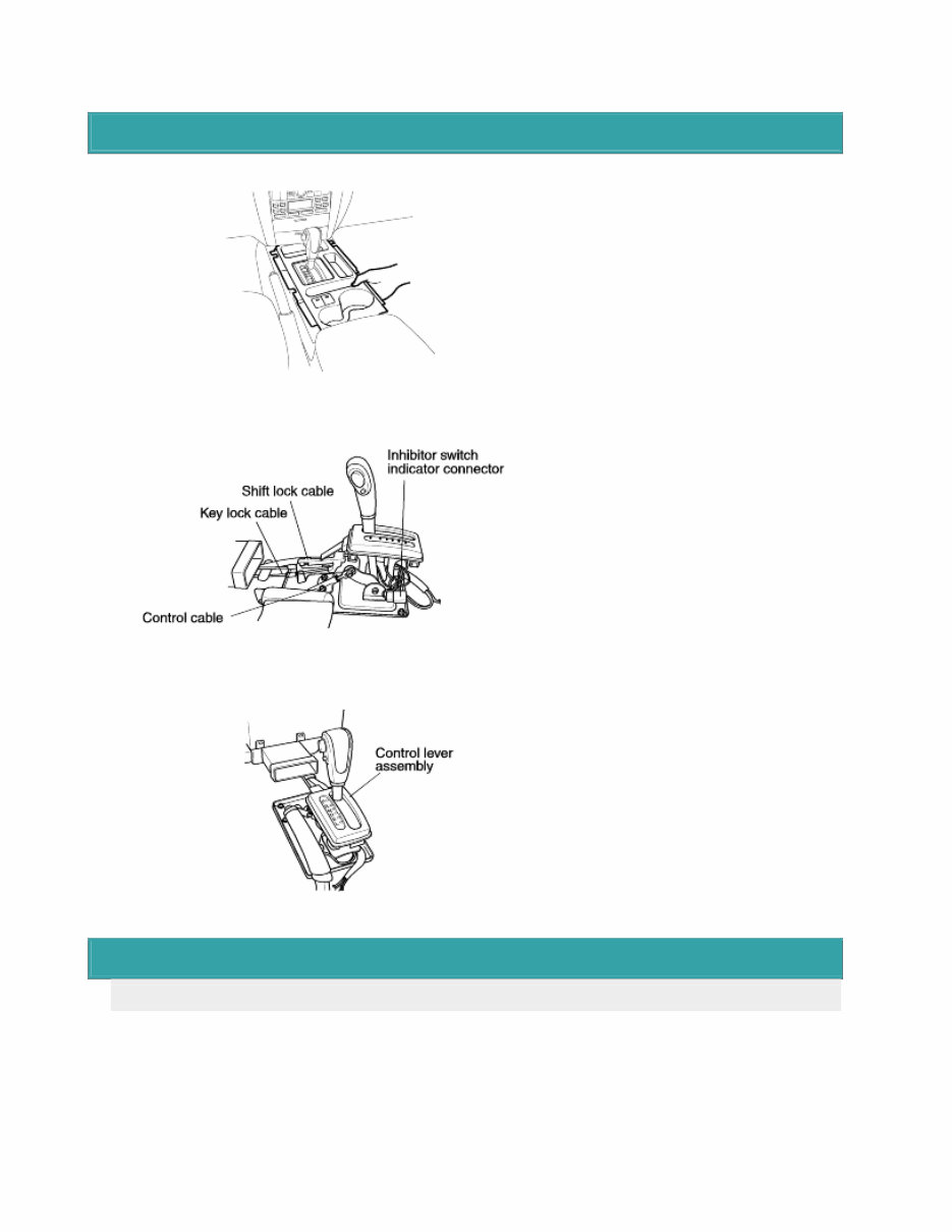
COMPONENTS
REMOVAL 1. Remove the console upper cover plate. 2. Remove the center console assembly. 3. Remove the control cable, the shift lock cable and key lock cable. 4. Disconnect the inhibitor switch indicator connector. 5. Remove the control lever assembly. 6. Remove the control lever bracket. SHIFT LOCK DEVICE INSTALLATION INSTRUCTIONS INSPECTION a. Check the detent place for wear. b. Check the bushing for wear or damage. c. Check the spring for damage or deterioration. d. Check the pin at the end of the rod assembly for wear.
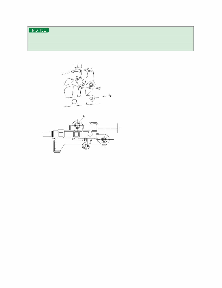
When servicing the shift lock device, follow the service instructions and procedures described below in order to operateit normally. 1. Procedure to install the lock cam. a. Make sure to move shift lever to position "P" to set key lock cam and p-lock as figure. 2. Procedure for adjusting "P" shift lock and key lock cable. (1) Check that lock cam is located in position. (2) Install shift lock cable in position as figure. (3) Temporarily install shift lock cable to A/T lever assembly as shown in figure. Securely insert cable end into fixing pin of cam. (4) After checking that a portion of cable end touches cable fixing pin of P-lock cam, fix shift lock cable to A/T lever. 3. Checking that procedure for installing the shift lock is correct. (1) When the brake pedal is not depressed, push button of the shift lever at "P" position cannot be operated. (Shift lever cannotbe shifted at the other positions from "P"). Push button can be operated at the other positions except "P". (2) When brake pedal stroke is 30 mm (with shift lever at "P" position), push button should be operated without catching and shift levercan be shifted smoothly to other from "P". (3) When brake pedal is not depressed, shift lever should be shifted smoothly to "P" position from other positions. (4) Brake pedal must be operated smoothly without catching at all positions. (5) If shift lever is shifted to "P" position, ignition key must be turned to "LOCK" position smoothly.
(6) Adjust nut "A" and bolt "B" if necessary.
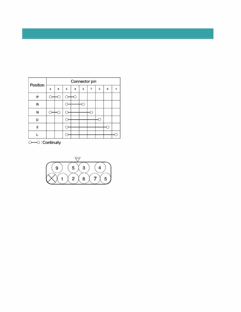
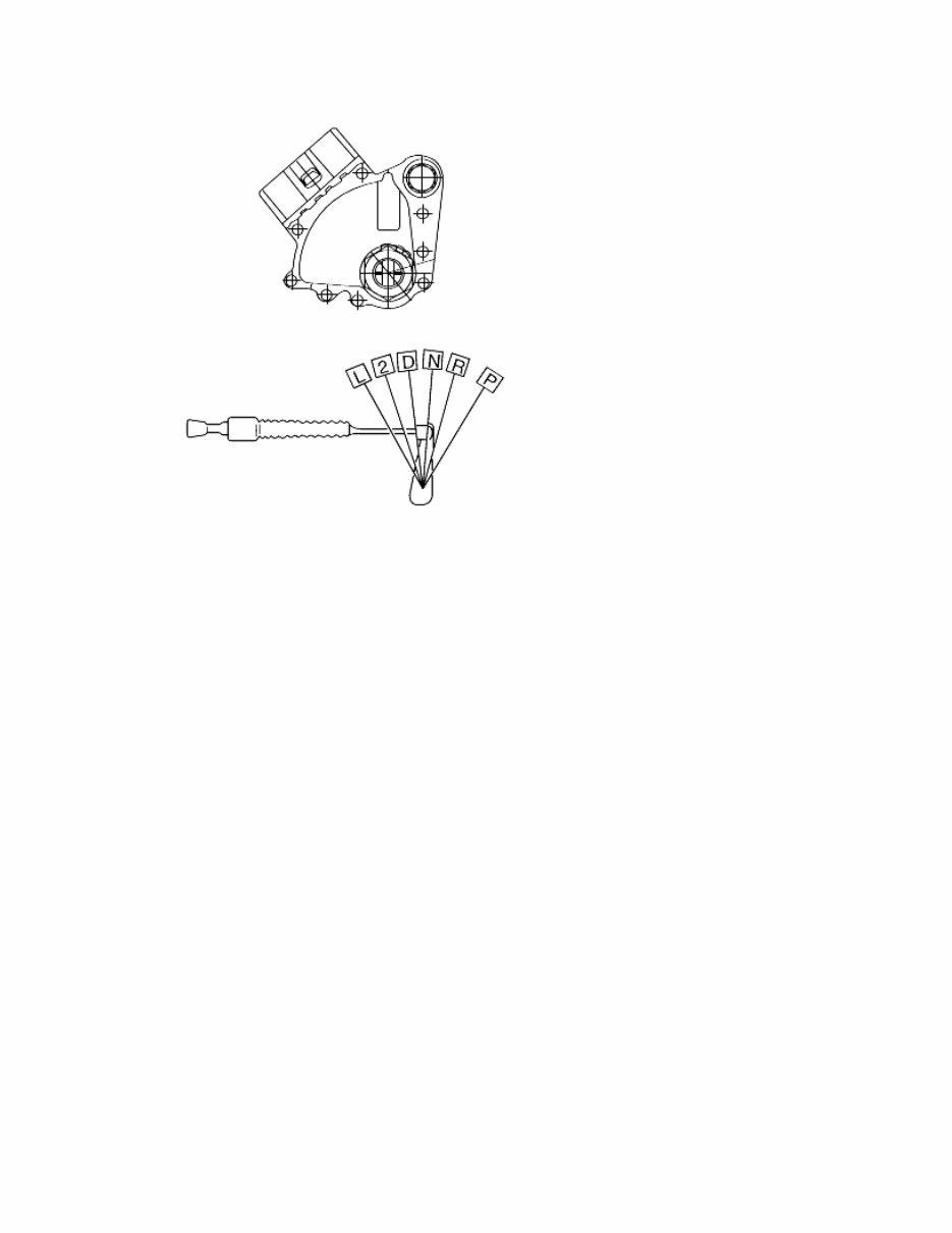
TRANSAXLE RANGE SWITCH 1. Operating inspection (1) Check that the starter turns with the ignition switch at START position and the selector in the "P" and "N range only. (2) Check that the back-up (reverse) lights illuminate when shifted to the "R" range with the ignition switch in the ON position. (3) Check the transaxle range switch if it is not working properly. 1. Adjustment (1) Shift the selector lever to the "N" range. (2) Loosen the transaxle range switch mounting bolts. (3) Disconnect the transaxle range switch connector. (4) Check the continuity of the terminals using ohmmeter. (5) Adjust the switch to the point where there is continuity between the terminals.
This 2003-2006 Kia Sorento OEM Service & Repair Manual provides detailed repair procedures, technical specs, and maintenance instructions for all major systems on the first-generation Sorento. This official manual is a must-have for any DIYer or technician working on the 3.5L DOHC V6 model.
Every section has been professionally structured for easy access, including wiring diagrams, torque specs, and complete diagnostic procedures. Whether you're tackling drivetrain repairs, suspension issues, or just keeping up with maintenance, this manual offers factory-level detail.
Content Overview:
General Information & Maintenance
Engine Mechanical (3.5L V6 DOHC)
Engine Performance & Emission Control
Electrical System & Wiring Diagrams
HVAC (Heating, Ventilation, A/C)
Transmission & Transaxle (coverage depends on model-specific config)
Suspension & Steering
Brakes (ABS and non-ABS)
Restraints & Airbags
Technical Service Bulletins
Torque Specs & Diagnostic Flowcharts
Whether you're servicing the engine, chasing down an electrical fault, or reviewing TSBs before a repair, this manual gives you the factory-approved procedures to do the job right the first time.
Printable: Yes Language: English Compatibility: Windows, macOS, Linux Requirements: PDF reader software