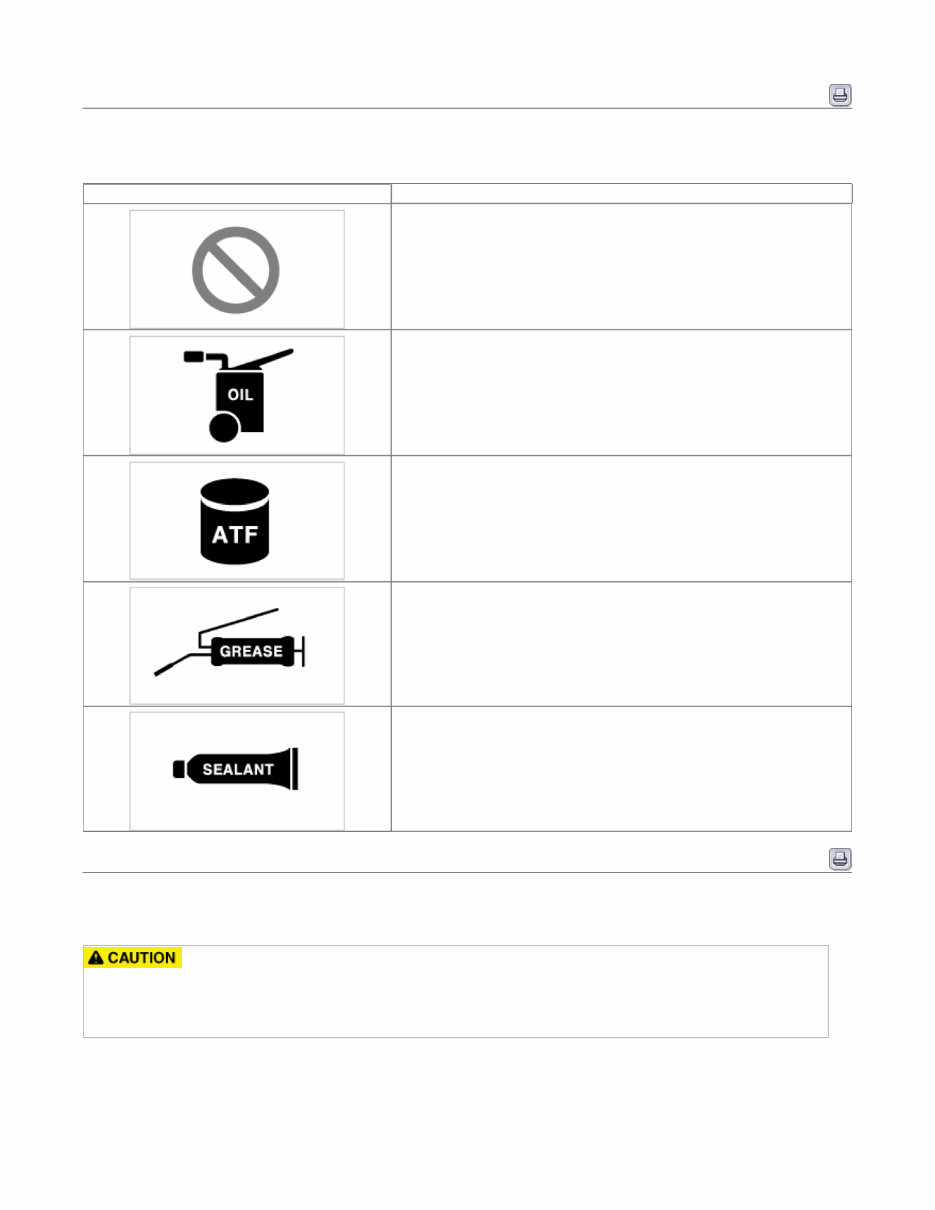
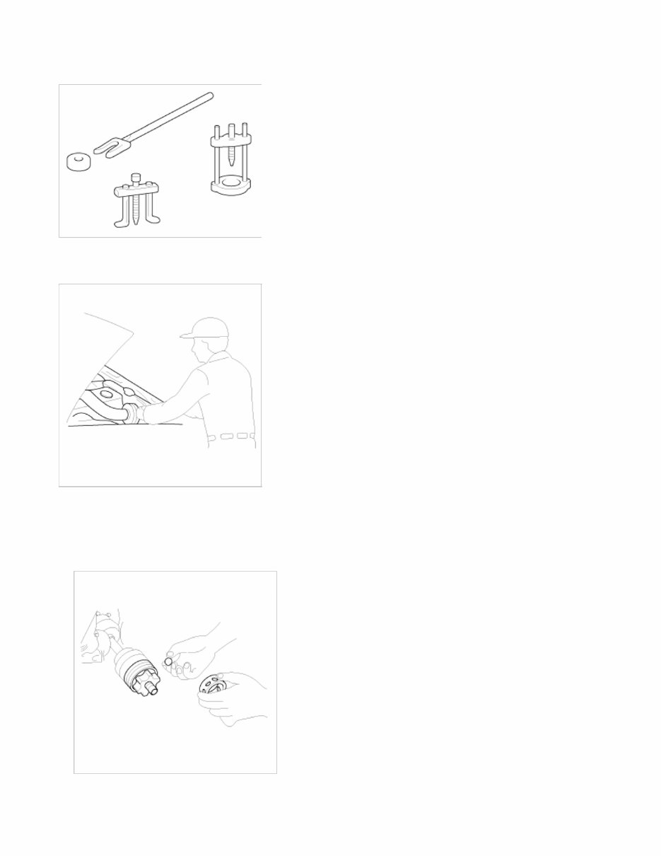
General Information General Information Basic Service Symbols There are five primary symbols used to complement illustrations. These symbols indicate the part to apply such materials during service. Symbol Meaning Do not reuse the part. Replace a new one. Apply engine oil or transmission oil to the part. Apply automatic transmission fluid (ATF) to the part. Apply grease to the part. Apply sealant to the part. General Service Information Protection Of The Vehicle Always be sure to cover fenders, seats, and floor areas before starting work. The support rod must be inserted into the hole near the edge of the hood whenever you inspect the engine compartment to prevent the hood from falling and causing possible injury. Make sure that the support rod has been released prior to closing the hood. Always check to be sure the hood is firmly latched before driving the vehicle. Preparation Of Tools And Measuring Equipment Be sure that all necessary tools and measuring equipment are available starting work. Page 1 sur 20
Special Tools Use special tools when they are required. Removal Of Parts First find the cause of the problem and then determine whether removal or disassembly before starting the job. Disassembly If the disassembly procedure is complex, requiring many parts to be disassembled, all parts should be disassembled in a way that will not affect their performance or external appearance. 1. Inspection of parts Each part, when removed, should be carefully on suspected for malfunction, deformation, damage, and other problems. 2. Arrangement of parts Page 2 sur 20
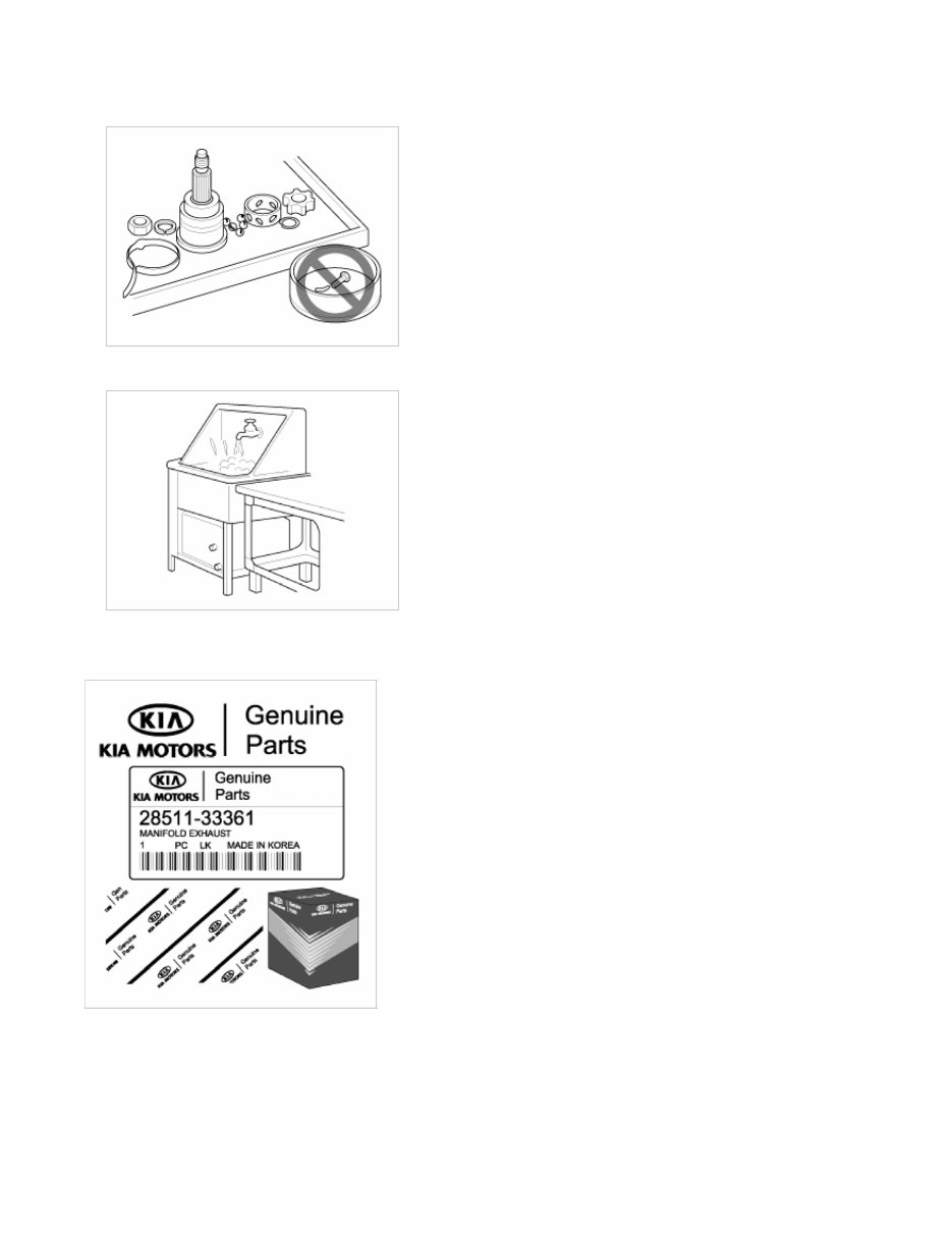
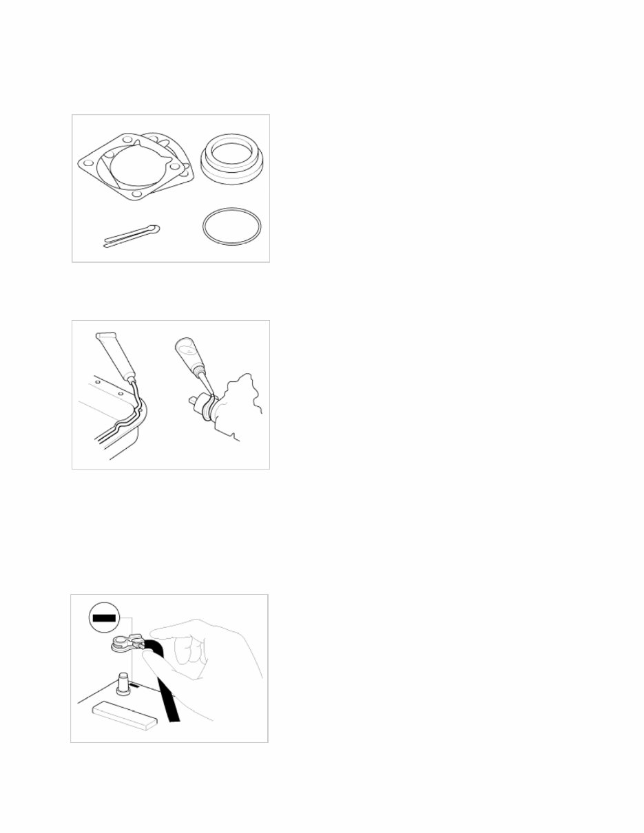
All disassembled parts should be carefully arranged for effective reassembly. Be sure to separate and correctly identify the parts to be replaced from those that will be used again. 3. Cleaning parts for reuse All parts to be used again should be carefully and thoroughly cleaned by an appropriate method. Parts When replacing parts, use KIA MOTORS genuine parts. Replacement Standard values, such as torques and certain adjustments, must be strictly observed in the reassembly of all parts. If removed, the following parts should always be replaced with new ones. 1. Oil seals 2. Gaskets 3. Page 3 sur 20
O-rings 4. Lock washers 5. Cotter pins (split pins) 6. Plastic nuts Depending on their location. 7. Sealant should be applied to gaskets. 8. Oil should be applied to the moving components of parts. 9. Specified oil or grease should be applied to the prescribed locations (oil seals, etc) before assembly. Adjustment Use gauges and testers to adjust correctly the parts to standard values correctly. Electrical System 1. Be sure to disconnect the battery cable from the negative (-) terminal of the battery. 2. Never pull on the wires when disconnecting connectors. 3. Locking connectors will click when the connector is secure. 4. Handle sensors and relays carefully. Be careful not to drop them against other parts. Rubber Parts And Tubes Page 4 sur 20
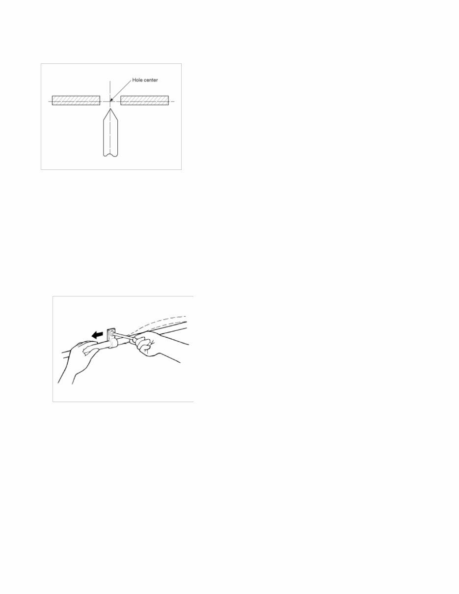
Always prevent gasoline or from touching rubber parts or tubing. Measuring Body Dimensions 1. Basically, all measurements in this manual are taken with a tracking gauge. 2. When a measuring tape is used, check to be sure there is no elongation, twisting or bending. 3. For measuring dimensions, both projected dimensions and actual - measurement dimensions are used in this manual. Dimensions Projected 1. These are the dimensions measured when the measurement points are projected from the vehicle's surface, and are the reference dimensions used for used for body alterations. 2. If the length of the tracking gauge probes is adjustable, measure it by lengthening one of two probes as long as the different value in height of the two surface. Measuring Actual Dimensions 1. These dimensions indicate the actual linear distance between measurement points, and are used as the reference dimensions when a tracking gauge is used for measurement. 2. First adjust both probes to the same length (A=A') before measurement. Check the probes and gauge itself to make sure there is no free play. Page 5 sur 20
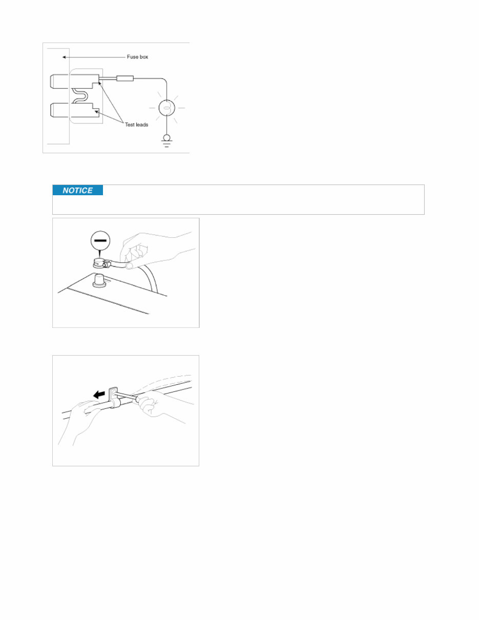
Measurement Point Measurements should be taken at the center of the hole. Checking Cables And Wires 1. Check the terminal for tightness. 2. Check terminals and wires for corrosion from battery electrolyte, etc. 3. Check terminals and wires for open circuits. 4. Check wire insulation and coating for damage, cracks and degrading. 5. Check the conductive parts of terminals for contact with other metallic parts (vehicle body and other parts). 6. Check grounded parts to verify that there is complete continuity between their attaching bolt(s) and the vehicle's body. 7. Check for incorrect wiring. 8. Check that the wiring is so clamped to the prevent contact with sharp corners of the vehicle body, etc. or hot parts (exhaust manifold, etc.) 9. Check that the wiring is clamped firmly to provide enough clearance from the fan pulley, fan belt and other rotating or moving parts. 10. Check that the wiring has a little space so that it can vibrate between fixed and moving parts such as the vehicle body and the engine. Check Fuses A blade type fuse test taps provided to allow checking the fuse itself without removing if from the fuse box. The fuse is good if the test lamp lights up when one lead is connected to the test taps (one at a time) and the other lead is grounded. (Turn the ignition switch so that the fuse circuit becomes operative) Page 6 sur 20
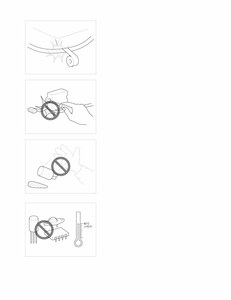
Servicing The Electrical System 1. Prior to servicing the electrical system, be sure to turn off the ignition switch and disconnect the battery ground cable. In the course of MFI or ELC system diagnosis, when the battery cable is removed, any diagnostic trouble code retained by the computer will be cleared. There fore, if necessary, record the diagnostic data before removing the battery cable. 2. Attach the wiring harnesses with clamps so that there is no slack. However, for any harness which passes the engine or other vibrating parts of the vehicle, allow some slack within a range that does not allow the engine vibrations to cause the harness to come into contact with any of the surrounding parts and then secure the harness by using a clamp. 3. If any section of a wiring harness interferes with the edge of a parts, or a corner, wrap the section of the harness with tape or something similar in order to protect if from damage. Page 7 sur 20
4. When installing any parts, be careful not to pinch or damage any of the wiring harness. 5. Never throw relays, sensors or electrical parts, or expose them to strong shock. 6. The electronic parts used in the computer, relays, etc. are readily damaged by heat. If there is a need for service operations that may cause the temperature to exceed 80°C (176°F), remove the electronic parts before hand. 7. Loose connectors cause problems. Make sure that the connectors are always securely fastened. Page 8 sur 20
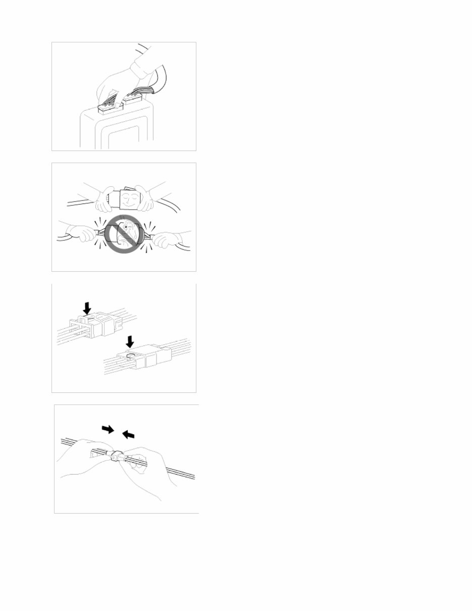
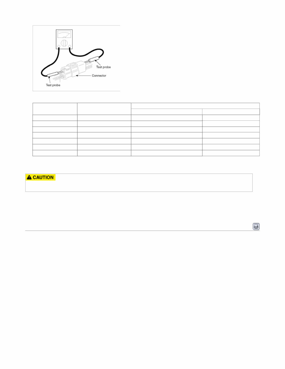
8. When disconnecting a connector, be sure to grip only the connector, not the wires. 9. Disconnect connector which have catches by pressing in the direction of the arrows shown the illustration. 10. Connect connectors which have catches by inserting the connectors until they make a clicking sound. 11. When using a circuit tester to check continuity or voltage on connector terminals, insert the test probe into the harness side. If the connector is a sealed connector, insert the test probe through the hole in the rubber cap until contacts the terminal, being careful not to damage the insulation of the wires. Page 9 sur 20
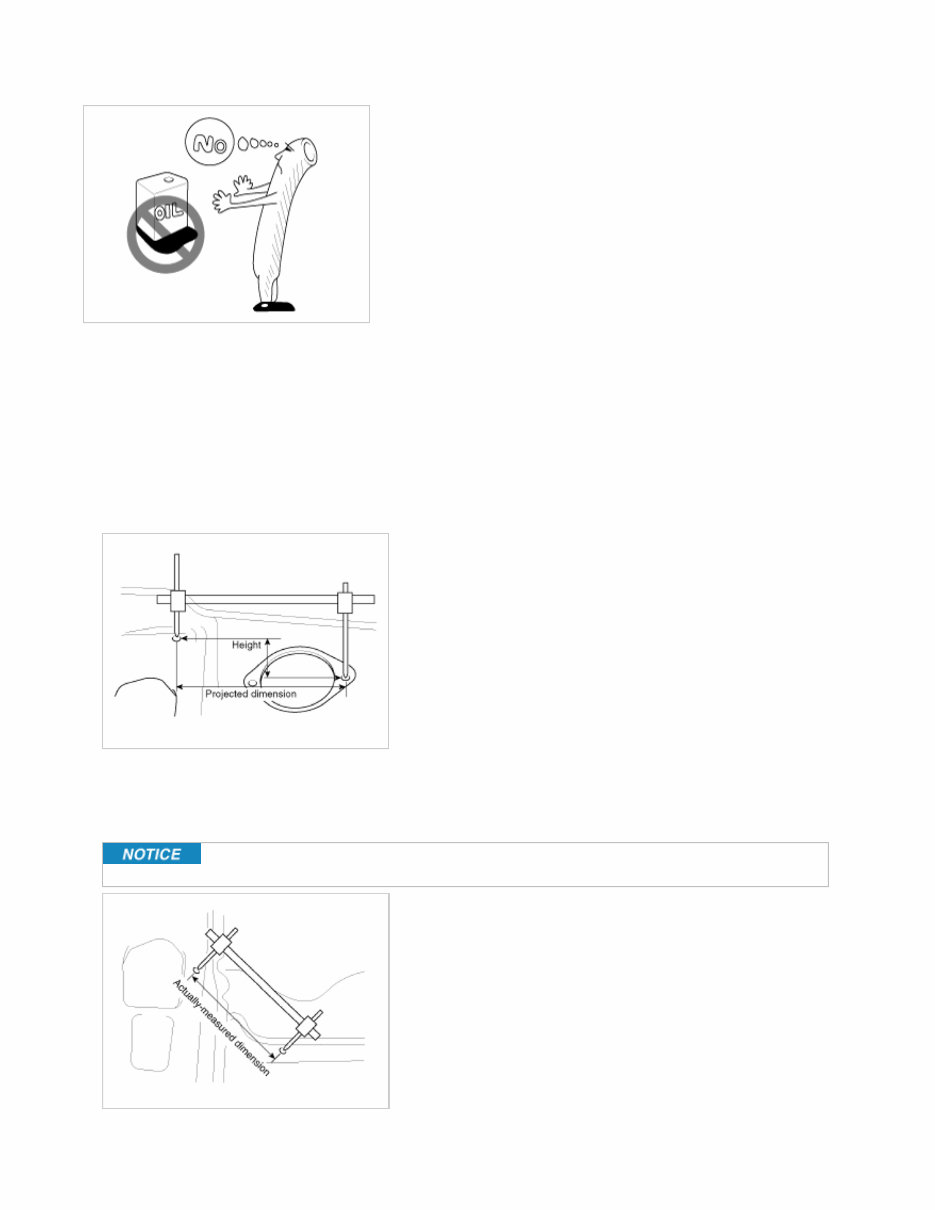
General Information 12. To avoid overloading the wiring, take the electrical current load of the optional equipment into consideration, and determine the appropriate wire size. Nominal size SAE gauge No. Permissible current In engine compartment Other areas 0.3mm² AWG 22 - 5A 0.5mm² AWG 20 7A 13A 0.85mm² AWG 18 9A 17A 1.25mm² AWG 16 12A 22A 2.0mm² AWG 14 16A 30A 3.0mm² AWG 12 21A 40A 5.0mm² AWG 10 31A 54A Precautions For Catalytic Converter If a large amount of unburned gasoline flows into the converter, it may overheat and create a fire hazard. To prevent this observe the following precautions and explain them to your customer. 1. Use only unleaded gasoline. 2. Do not run the engine while the car is at rest for a long time. Avoid running the engine at fast idle for more than 10 minutes and idle speed for more than 20 minutes. 3. Do not measure engine compression for an extended time. Engine compression tests must be made as rapidly as possible. Remove the fuel pump relay before performing a compression test. 4. Do not dispose of used catalytic converter together with parts contaminated with gasoline or oil. Identification Numbers Page 10 sur 20
The Kia Sedona 2016 Factory Service Repair Manual is the ultimate resource for maintaining and repairing your Kia Sedona 2016 model. Designed by experts, this manual provides detailed and comprehensive instructions for all aspects of servicing and repairing your vehicle.
Whether you are a professional mechanic or a Kia Sedona owner who prefers to do their own repairs, this manual is a must-have. It covers a wide range of topics, including engine maintenance, transmission repairs, electrical systems, brakes, suspension, and much more.
With this manual, you can easily find step-by-step instructions and diagrams for any repair or maintenance task. It is organized in a user-friendly format, allowing you to quickly locate the information you need. The manual is also accompanied by detailed illustrations, making it easier to understand the procedures.
Compatible Models:
Kia Sedona 2016 LX
Kia Sedona 2016 EX
Kia Sedona 2016 SX
Invest in the Kia Sedona 2016 Factory Service Repair Manual and give yourself the confidence to tackle any repair or maintenance task on your Kia Sedona with ease!