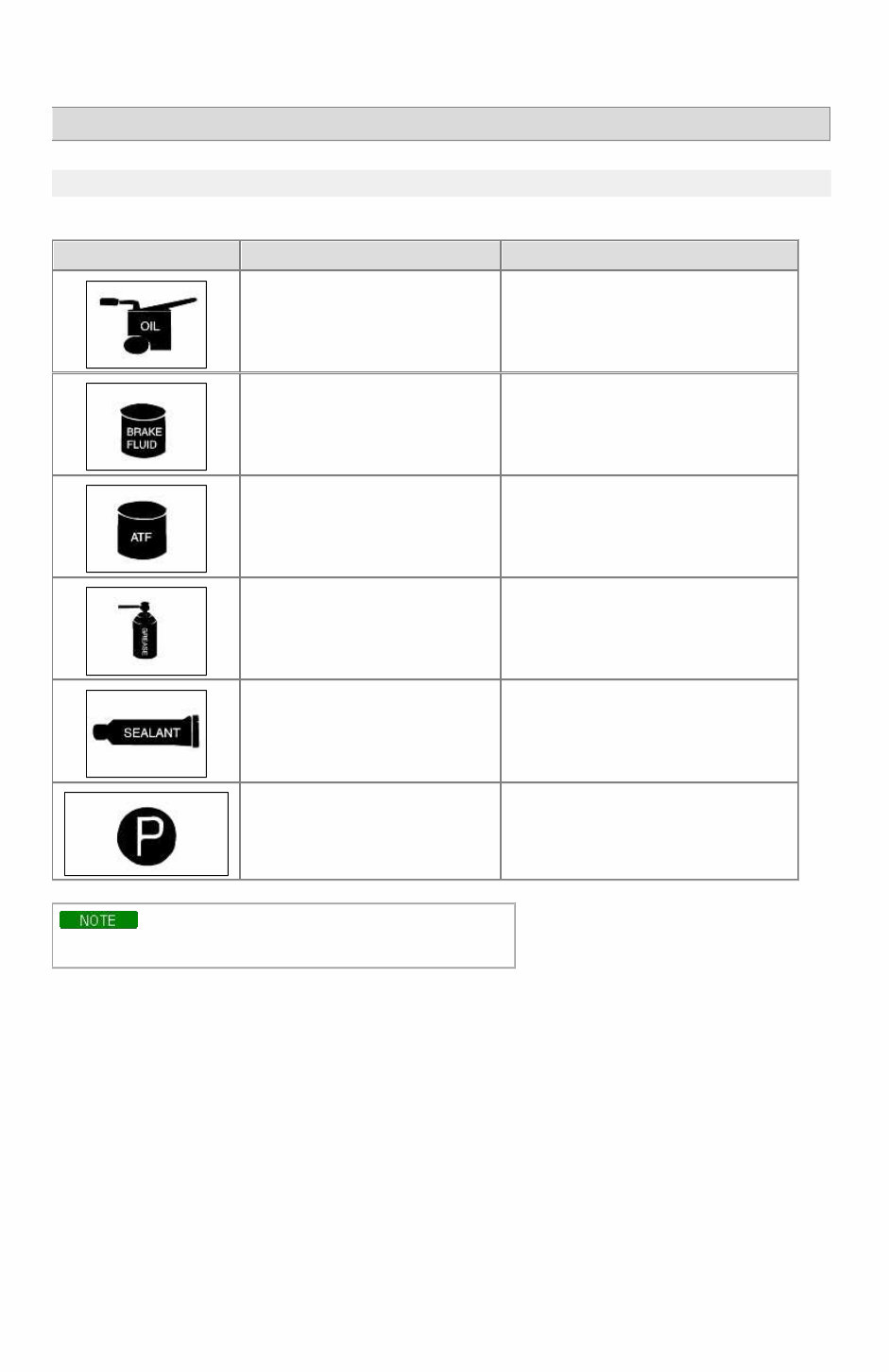
RIO(BC) > 2004 > G 1.6 DOHC > General Information General Information > General Information > General Information FUNDAMENTAL PROCEDURES SYMBOLS There are six primary symbols used to complement illustrations. These symbols indicate the areas to apply such materials during service. Symbol Meaning Type Apply oil New engine oil, gear oil, etc. as appropriate Apply brake fluid Only brake fluid Apply automatic transmission fluid (ATF) Only ATF Apply grease Appropriate grease Apply sealant Appropriate sealant Apply petroleum jelly Appropriate petroleum jelly Whenever special oil or grease is required, it will be identified in figure. Notice, Cautions and Warnings As you read through the various procedures, you will encounter Notice, Cautions and Warnings.Each one is there for a specific purpose.Notice give you added information that will assist you in completing particular procedure. Cautions prevent you from making an error that could damage the vehicle. Warnings remind you to be especially careful in specific areaswhere carelessness can cause personal injury. The following items contain general procedures you should always follow when working on a vehicle: Protection of vehicle Always cover fenders, seats, and floor are as before starting work. Operate the engine only in a well-ventilated area to avoid carbon monoxide poisoning. Page 1 of 15
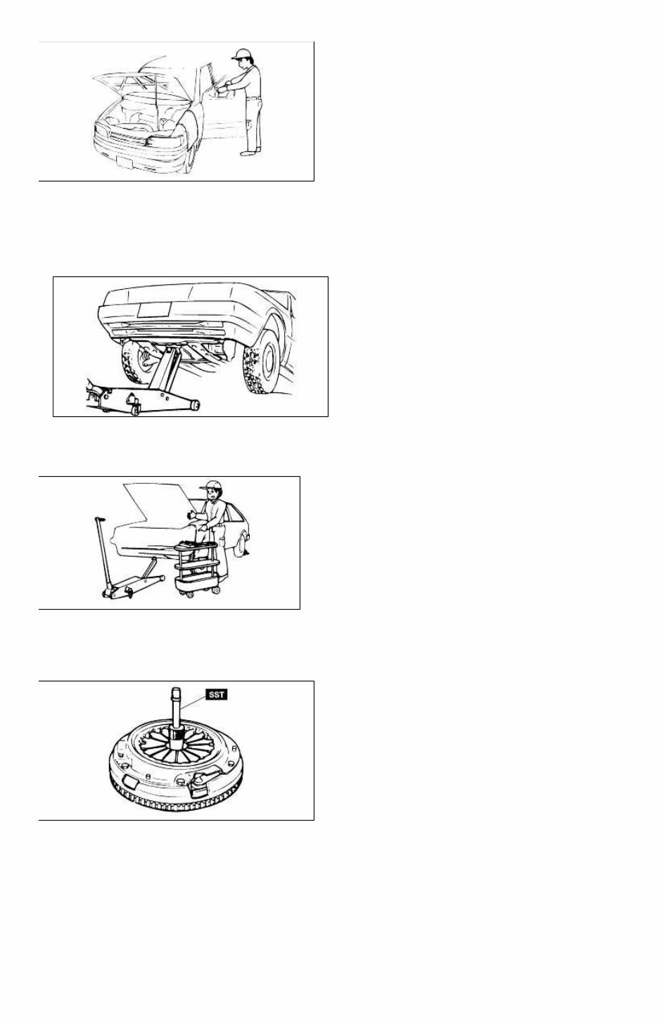
A word about safety The following precautions must be followed when jacking up the vehicle: 1. Block the wheels. 2. Use only the specified jacking positions. 3. Support the vehicle with safety stands. The engine compartment must be clear of tools and people before starting the engine. Preparation of tools and measuring equipment All necessary tools and measuring equipment should be available before starting any work. Special service tools (SST's) Use special service tools when they are required. SST's can be found under "preparation" prior to any procedure requiring them. Removal of parts Begin work only after first learning which parts and subassemblies must be removed and disassembled for replacement or repair. Page 2 of 15
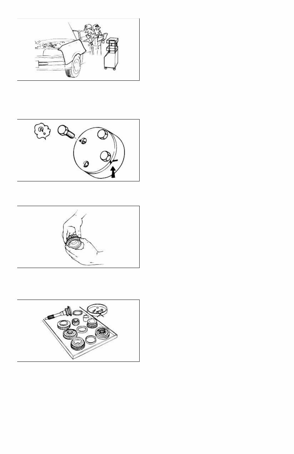
Disassembly If the disassembly procedure is complex, requiring many parts to be disassembled, all parts should be disassembled in a way that will not affect their performance or external appearance. Additionally, these parts should be identified so that reassembly can be done easily and efficiently. Inspection of parts When removed, each part should be carefully inspected for malfunction, deformations, damage, or other problems. Arrangement of parts All disassembled parts should be carefully arranged for reassembly. Separate or otherwise identify the parts to be replaced from those that will be reused. Cleaning parts for reuse All parts that will be reused should be carefully and thoroughly cleaned using appropriate methods. Page 3 of 15
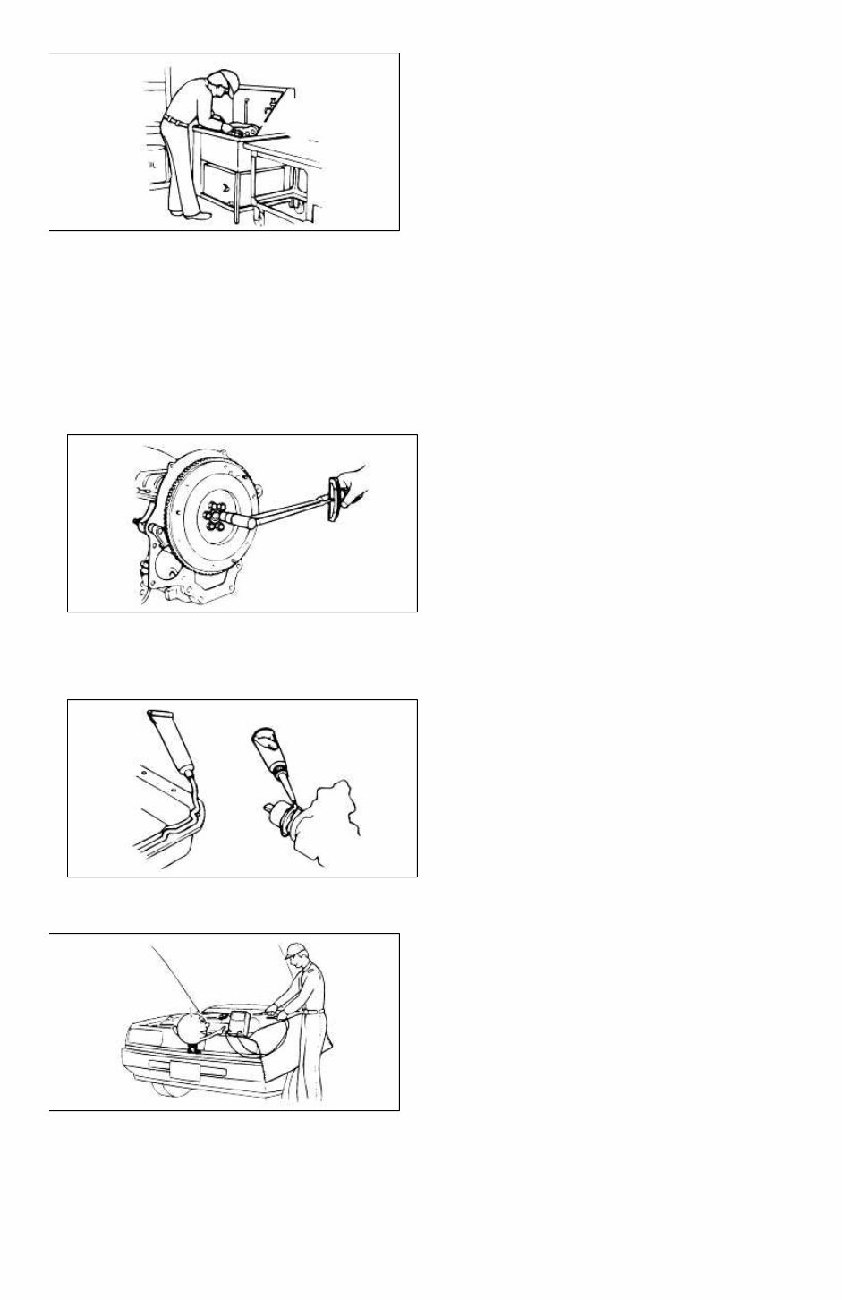
Reassembly Standard values, such as torques and certain adjustments, must be strictly observed in the reassembly of all parts. If removed, the following parts should be replaced with new ones: 1. Oil seals 2. O-rings 3. Cotter pins 4. Gaskets 5. Lock washers 6. Nylon nuts Depending on location: 1. Sealant should be applied or new gaskets installed. 2. Oil should be applied to the moving components of parts. 3. Specified oil or grease should be applied at the appropriate locations (such as oil seals) before reassembly. Adjustments Use appropriate gauges and/or testers when making adjustments. Rubber parts and tubing Prevent gasoline or oil from contacting rubber parts or tubing. Page 4 of 15
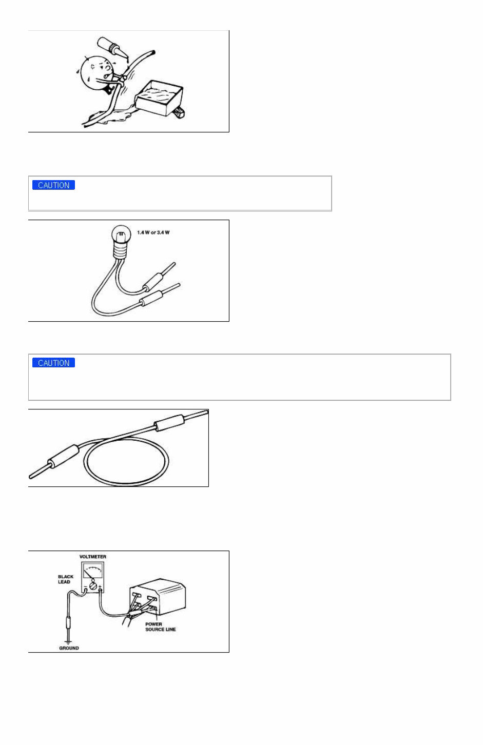
Electrical troubleshooting tools (Test Light) The test light, as shown in figure, uses a 12V bulb. The two lead wires should be connected to probes. The test light is used for simple voltage checks and in checking for short circuits. When checking the engine control module (ECM), never use a bulb exceeding 3.4W. Electrical troubleshooting tools(Jumper wire) The jumper wire is used for testing by shorting across switch terminals and ground connections. Do not connect a jumper wire from the power source line to a body ground. Such a connection may cause damage to harnesses or electronic components. Electrical troubleshooting tools(Voltmeter) The DC voltmeter measures circuit voltage. A voltmeter with a range of 15V or more is used by connecting the positive (+) probe (red lead wire) to the point where voltage is to be measured, and the negative (-) probe (black lead wire) to a body ground. Electrical troubleshooting tools(Ohmmeter) The ohmmeter is used to measure the resistance between two points in a circuit and also to check for continuity and the diagnosis of short circuits. Page 5 of 15
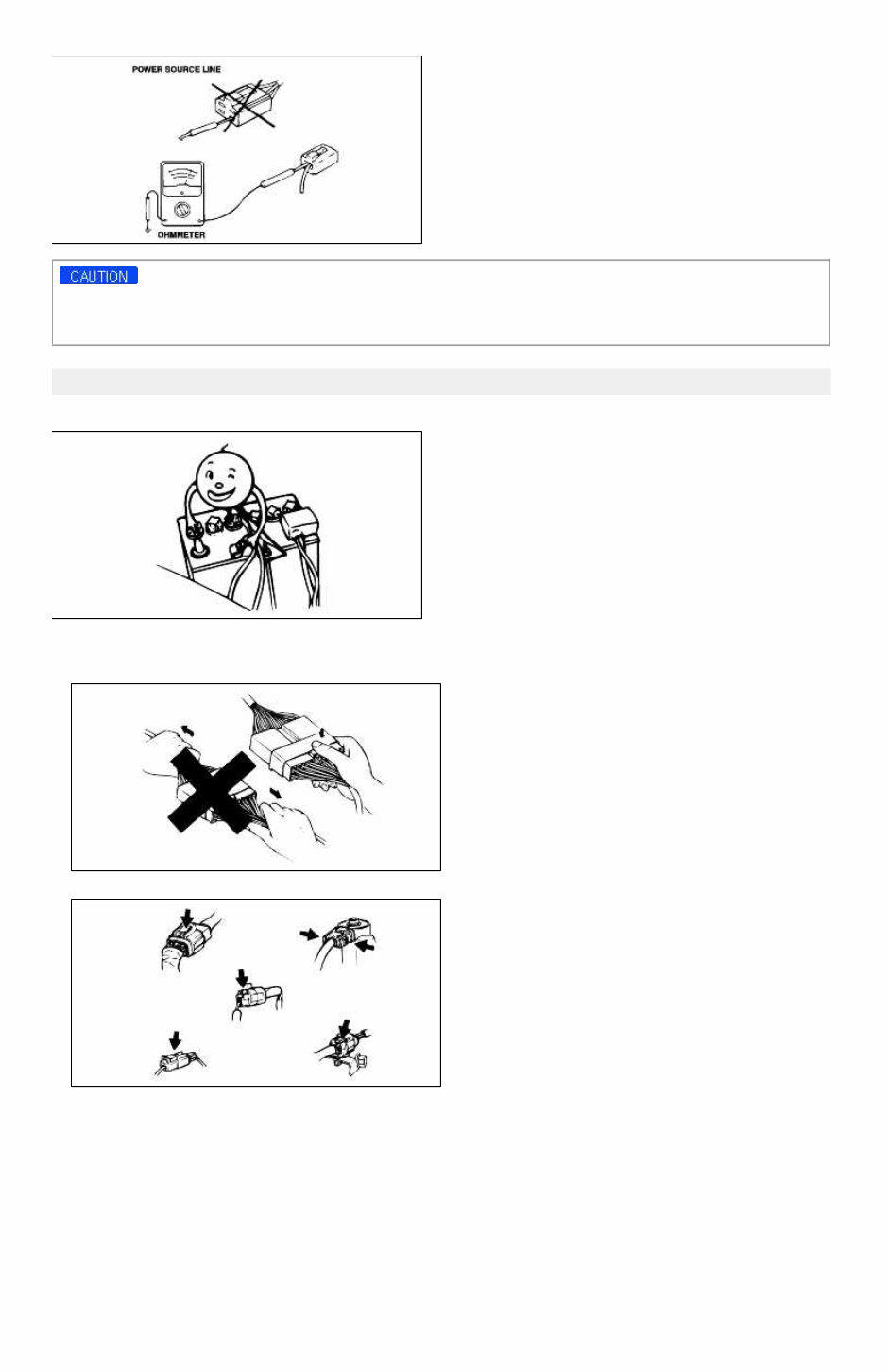
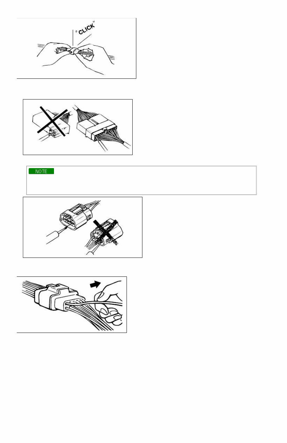
Do not attempt to connect the ohmmeter to any circuit in which voltage is applied. Such a connection may damage the ohmmeter. Electrical parts Battery cable Before disconnecting connectors or replacing electrical parts, disconnect the negative battery cable. Connectors(Removal of connector) 1. Never pull on the wiring harness when disconnecting connectors. 2. Connectors can be removed by pressing or pulling lock lever. Connectors(Locking a connector) Listen for a click when locking connectors. This sound indicates that they are securely locked. Page 6 of 15
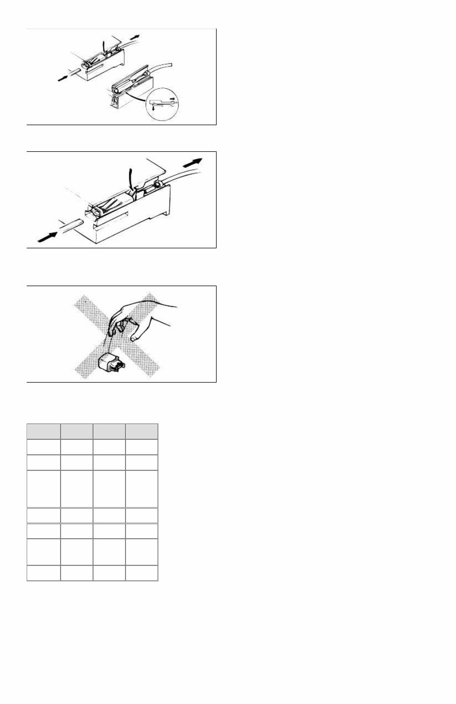
Connectors(Inspection) 1. When a tester is used to check for continuity or to measure voltage, insert tester probe from wire harness side. 2. Check terminals of waterproof connectors from connector side because they cannot be accessed from harness side. • Use a fine wire to prevent damage to the terminal. • Do not damage the terminal when inserting the tester lead. Terminals(Inspection) Pull lightly on individual wires to ensure that they are secured in the terminal. Terminals(Replacement of terminals) Use appropriate tools to remove terminal as shown. When installing the terminal, insert it until it locks securely. Insert a thin piece of metal from the terminal side of the connector, and then, with the terminal locking tab pressed down, pull the terminal out of the connector. Page 7 of 15
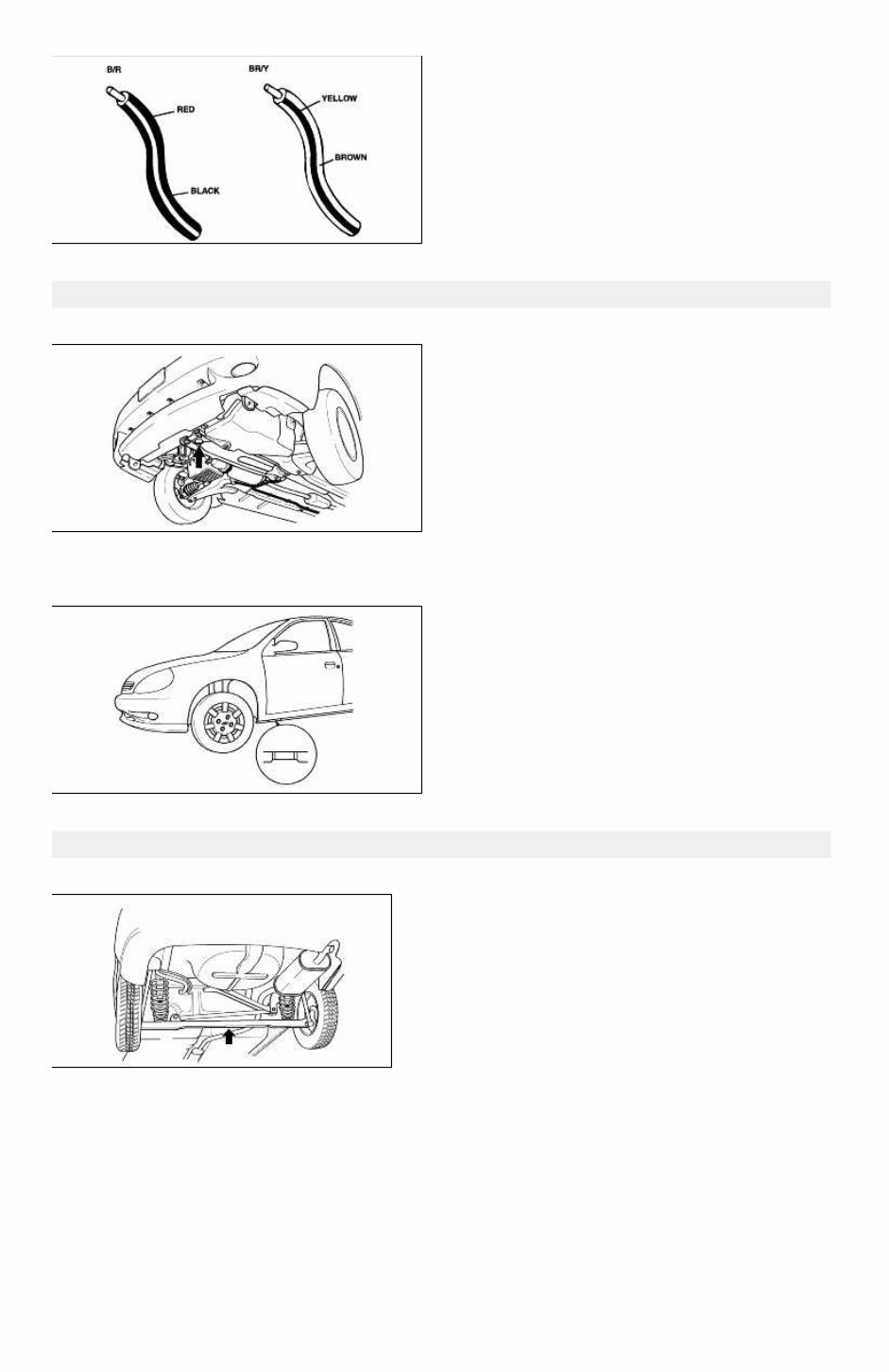
Follow the same procedure as female-type terminal. Terminals(Sensors, switches, and relays) Always handle sensors, switches, and relays carefully. Do not drop them or accidentally strike them against other parts. Wiring color codes Two-color wires are indicated by a two-color code symbol. The first color indicates the base color of the wire; the second color indicates the color of the stripe. Code Color Code Color B Black P Pink Br Brown R Red G Green S Silver (Light blue) Gy Gray T Tawny L Blue V Violet Lg Light green W White O Orange Y Yellow Page 8 of 15
Jack and safety stand positions Front end Jack position: At the front subframe Safety stand positions: On both sides of the side sills Jack and safety stand positions Jack position: At the center of the rear crossmember Safety stand positions: On both sides of the side sills Page 9 of 15
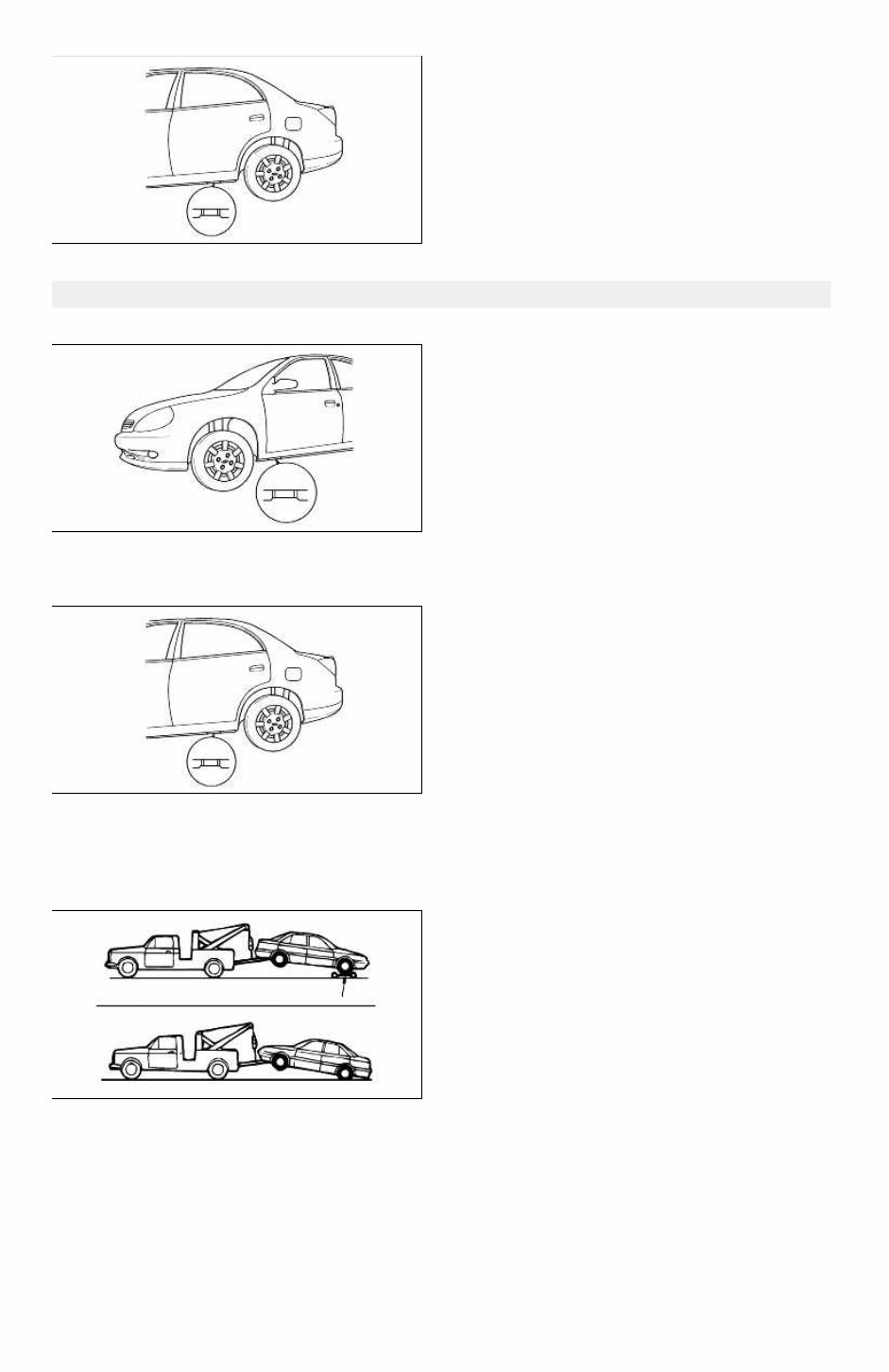
VEHICLE LIFT(2-SUPPORT TYPE) POSITIONS Front end Side sills(both sides) Rear end Side sills(both sides) Towing Proper towing equipment is necessary to prevent damage to the vehicle. Always observe laws and regulations applicable to vehicles in tow. As a general rule, towed vehicles should be pulled with the driving wheels off the ground. If excessive damage or other conditions prevent towing the vehicle with the driving wheels off the ground, use wheel dollies. With either automatic or manual transmission: 1. Set the ignition switch in the ACC position. 2. Place the selector lever or shift lever in N (Neutral). Page 10 of 15
This comprehensive factory service manual is an essential resource for maintaining and repairing your 2004 Kia Rio. It is extensively bookmarked, searchable, and features a clickable contents page for easy navigation.
Utilized by professional mechanics and dealerships, this manual covers a wide range of systems and components, including but not limited to General Information, Automatic Transaxle System, Body Interior/Exterior, Body Electrical System, Brake System, Clutch System, Driveshaft and Axle, Emission Control System, Engine Electrical System, Engine Mechanical System, Fuel System, Heating, Ventilation, Air Conditioning, Manual Transaxle System (STC), Restraint, Steering System, and Suspension System.
You can conveniently access the complete manual on your computer, print necessary sections, and discard the printouts when no longer needed. The manual contains detailed photos, exploded views, diagrams, and comprehensive information about the Kia Rio.
By following the step-by-step procedures and detailed illustrations provided in this manual, you can save on maintenance and repair costs. Many maintenance tasks are simpler than you may realize, making DIY repairs a cost-effective option.
Backing up the manual to a CD/DVD or any preferred method is possible, ensuring that you have a secure copy for future reference. Unlike other manuals, this manual allows you to safeguard the data and avoid the risk of repurchasing.
System Requirements: PC or Mac, Internet, & Adobe Acrobat Reader X. You can download the latest version of Adobe Acrobat Reader for FREE at www.adobe.com/products/reader.html.
Language: English
Format: PDF
For more information, visit our affiliate site at www.pacificcoastmanuals.com.