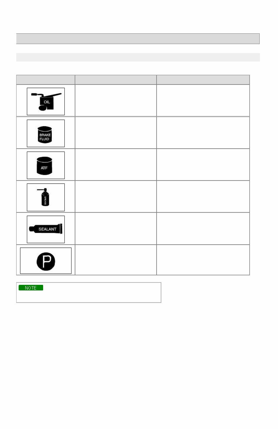
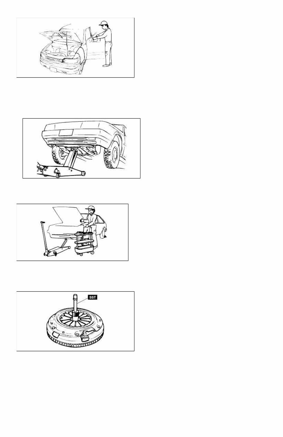
RIO(BC) > 2005 > G 1.6 DOHC > General Information General Information > General Information > General Information FUNDAMENTAL PROCEDURES SYMBOLS There are six primary symbols used to complement illustrations. These symbols indicate the areas to apply such materials during service. Symbol Meaning Type Apply oil New engine oil, gear oil, etc. as appropriate Apply brake fluid Only brake fluid Apply automatic transmission fluid (ATF) Only ATF Apply grease Appropriate grease Apply sealant Appropriate sealant Apply petroleum jelly Appropriate petroleum jelly Whenever special oil or grease is required, it will be identified in figure. Notice, Cautions and Warnings As you read through the various procedures, you will encounter Notice, Cautions and Warnings.Each one is there for a specific purpose.Notice give you added information that will assist you in completing particular procedure. Cautions prevent you from making an error that could damage the vehicle. Warnings remind you to be especially careful in specific areaswhere carelessness can cause personal injury. The following items contain general procedures you should always follow when working on a vehicle: Protection of vehicle Always cover fenders, seats, and floor are as before starting work. Operate the engine only in a well-ventilated area to avoid carbon monoxide poisoning. Page 1 of 15
A word about safety The following precautions must be followed when jacking up the vehicle: 1. Block the wheels. 2. Use only the specified jacking positions. 3. Support the vehicle with safety stands. The engine compartment must be clear of tools and people before starting the engine. Preparation of tools and measuring equipment All necessary tools and measuring equipment should be available before starting any work. Special service tools (SST's) Use special service tools when they are required. SST's can be found under "preparation" prior to any procedure requiring them. Removal of parts Begin work only after first learning which parts and subassemblies must be removed and disassembled for replacement or repair. Page 2 of 15
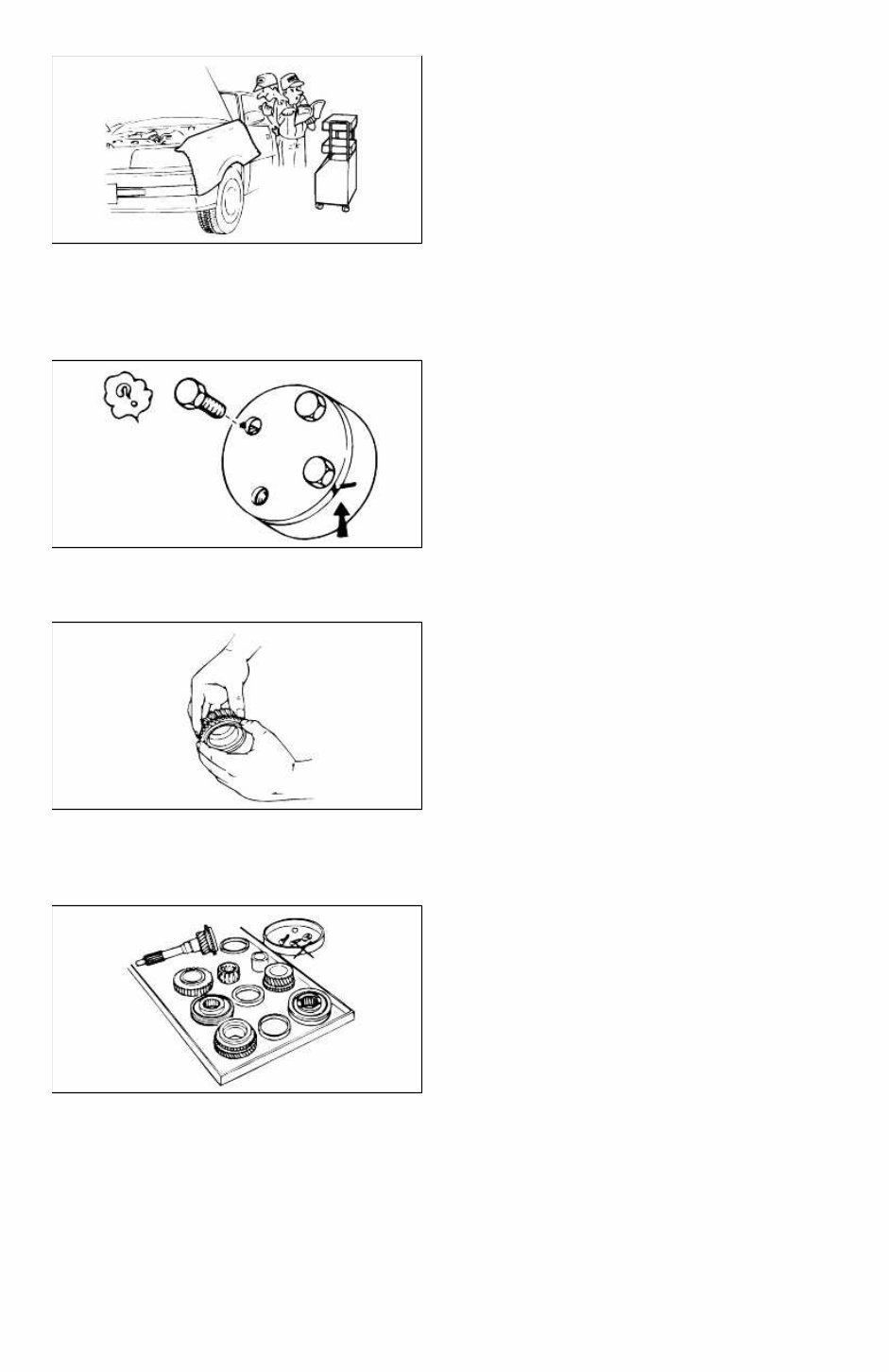
Disassembly If the disassembly procedure is complex, requiring many parts to be disassembled, all parts should be disassembled in a way that will not affect their performance or external appearance. Additionally, these parts should be identified so that reassembly can be done easily and efficiently. Inspection of parts When removed, each part should be carefully inspected for malfunction, deformations, damage, or other problems. Arrangement of parts All disassembled parts should be carefully arranged for reassembly. Separate or otherwise identify the parts to be replaced from those that will be reused. Cleaning parts for reuse All parts that will be reused should be carefully and thoroughly cleaned using appropriate methods. Page 3 of 15
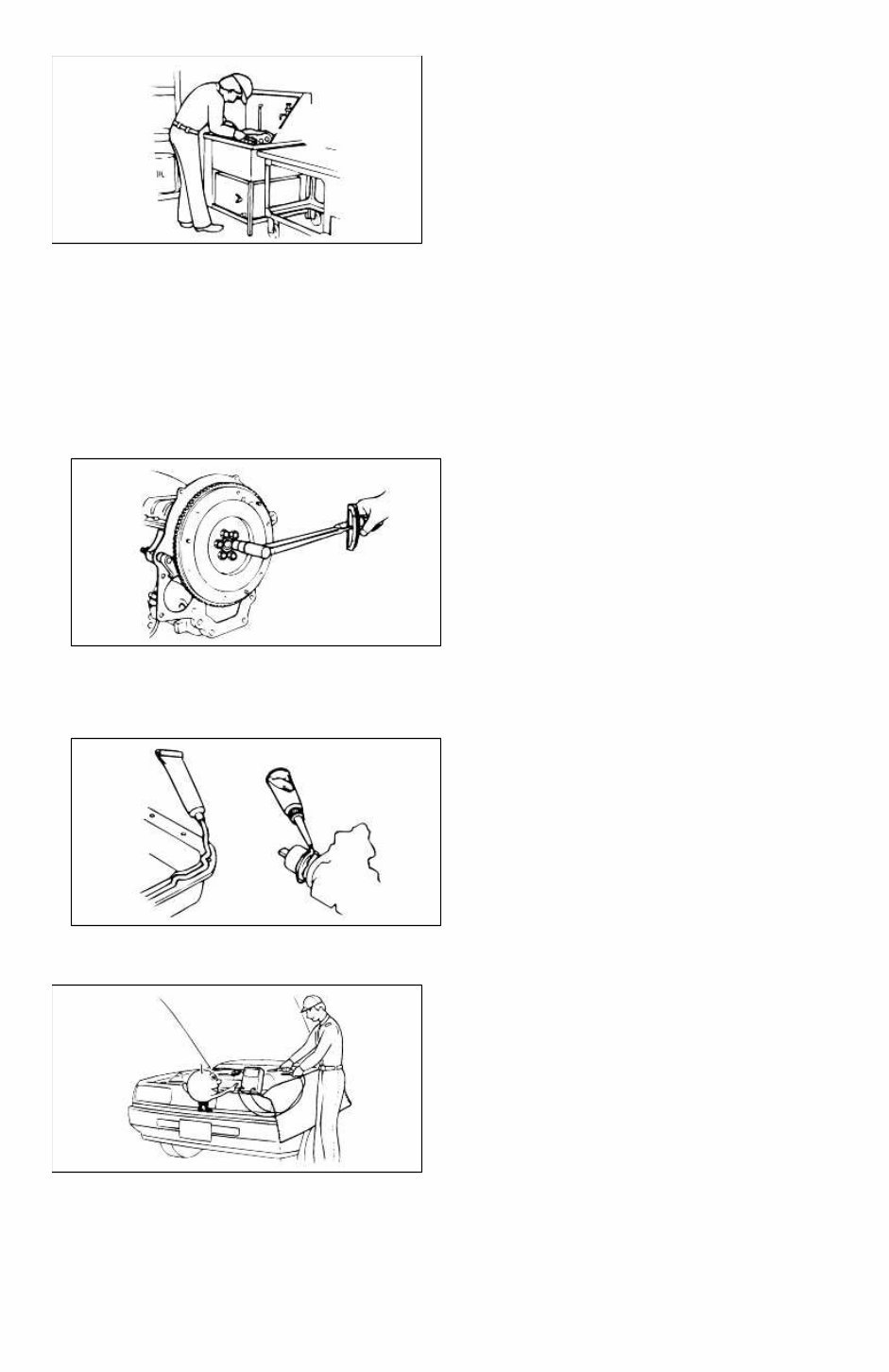
Reassembly Standard values, such as torques and certain adjustments, must be strictly observed in the reassembly of all parts. If removed, the following parts should be replaced with new ones: 1. Oil seals 2. O-rings 3. Cotter pins 4. Gaskets 5. Lock washers 6. Nylon nuts Depending on location: 1. Sealant should be applied or new gaskets installed. 2. Oil should be applied to the moving components of parts. 3. Specified oil or grease should be applied at the appropriate locations (such as oil seals) before reassembly. Adjustments Use appropriate gauges and/or testers when making adjustments. Rubber parts and tubing Prevent gasoline or oil from contacting rubber parts or tubing. Page 4 of 15
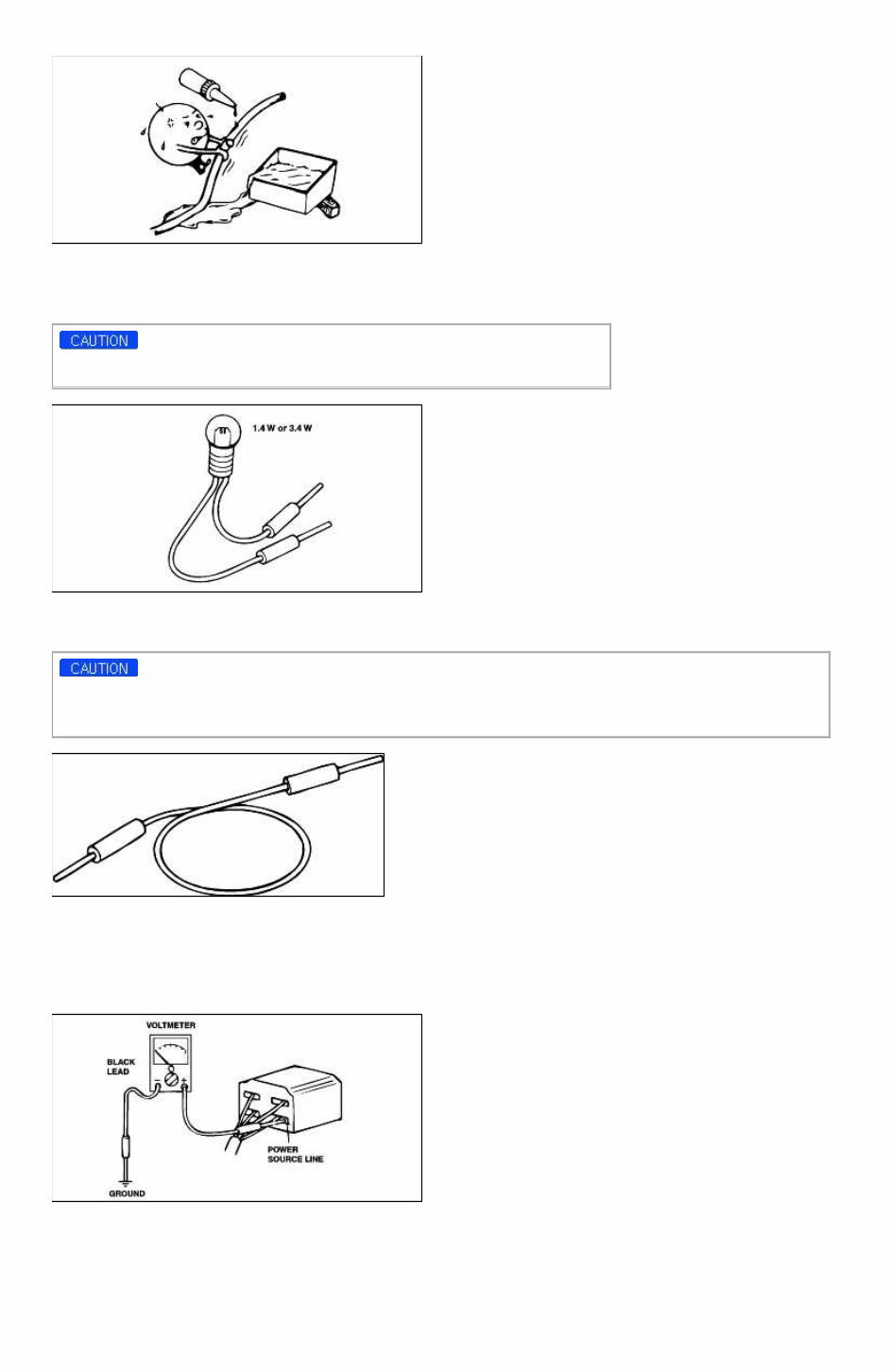
Electrical troubleshooting tools (Test Light) The test light, as shown in figure, uses a 12V bulb. The two lead wires should be connected to probes. The test light is used for simple voltage checks and in checking for short circuits. When checking the engine control module (ECM), never use a bulb exceeding 3.4W. Electrical troubleshooting tools(Jumper wire) The jumper wire is used for testing by shorting across switch terminals and ground connections. Do not connect a jumper wire from the power source line to a body ground. Such a connection may cause damage to harnesses or electronic components. Electrical troubleshooting tools(Voltmeter) The DC voltmeter measures circuit voltage. A voltmeter with a range of 15V or more is used by connecting the positive (+) probe (red lead wire) to the point where voltage is to be measured, and the negative (-) probe (black lead wire) to a body ground. Electrical troubleshooting tools(Ohmmeter) The ohmmeter is used to measure the resistance between two points in a circuit and also to check for continuity and the diagnosis of short circuits. Page 5 of 15
Kia Rio Complete Workshop Service Repair Manual 2008 2009
Thanks for taking the time to look at this Complete Service Repair Workshop Manual.
This manual covers every Service & Repair Procedure you will need.
DESCRIPTION:
You can now save yourself BIG money by doing your own repairs! This manual makes any service or repair job easy to do with very easy to follow step-by-step instructions & pictures on all areas of servicing & repairs. Once you have this manual it is yours to keep forever. You can print out one page, chapter or the whole thing. You can also transfer it to your tablet or smart phone if required.
MODELS COVERED:
All Models/Engines/Trim/Transmissions Types Are Covered.
CONTENTS:
This high quality Service Repair Workshop Manual covers all repair procedures A-Z.
Every repair and service procedure is covered.
COMPUTER REQUIREMENTS:
This downloadable Manual will work on All PC & MAC Computers, tablets, mobile phones Etc. The only software needed is adobe reader which in most cases is already loaded onto your computer, if not can be downloaded for free.
INSTANT DELIVERY:
This manual will be instantly emailed to the email address you used when checking out after receiving your payment by Visa, MasterCard or PayPal.