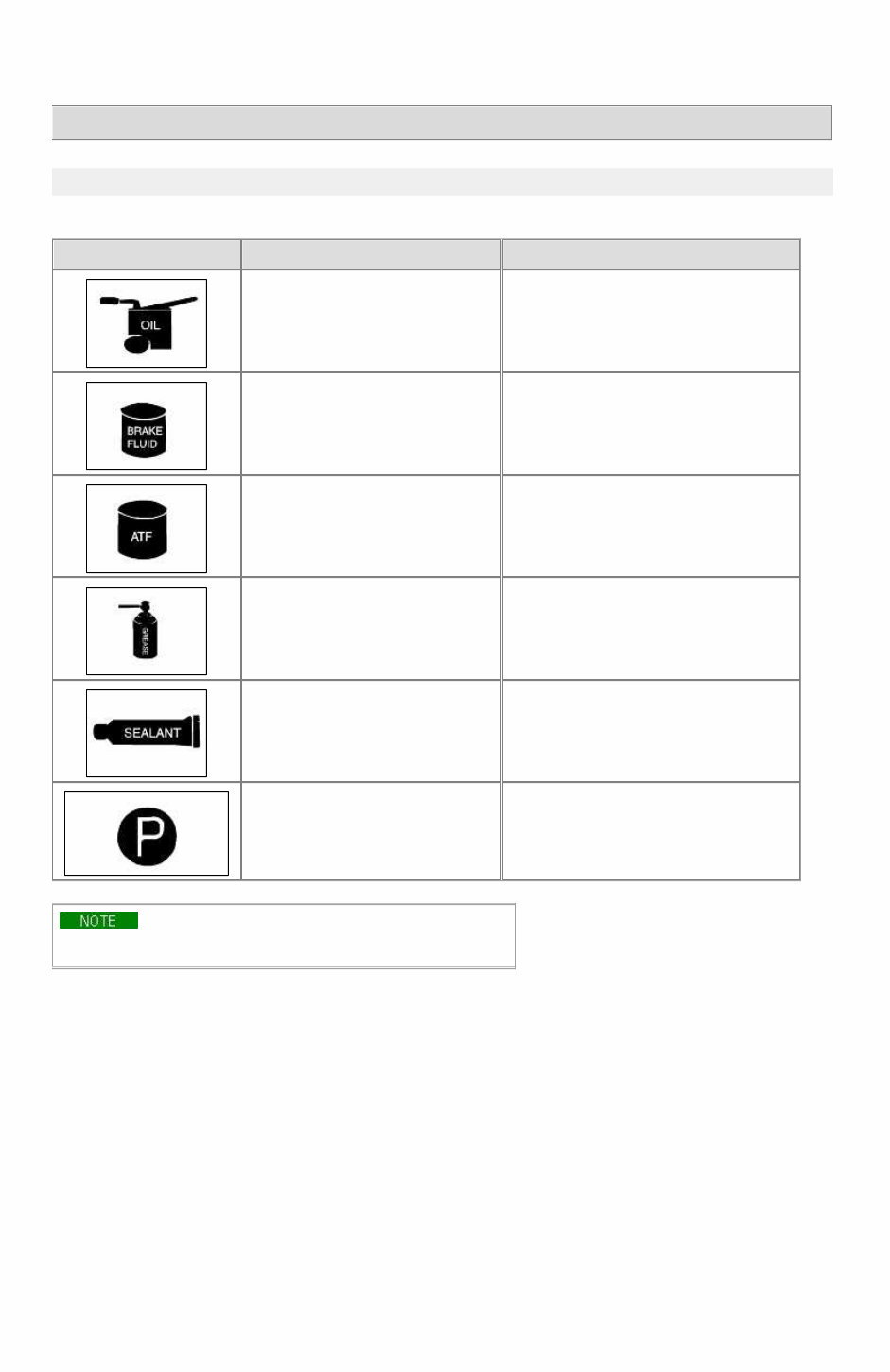
RIO(BC) > 2003 > G 1.6 DOHC > General Information General Information > General Information > General Information FUNDAMENTAL PROCEDURES SYMBOLS There are six primary symbols used to complement illustrations. These symbols indicate the areas to apply such materials during service. Symbol Meaning Type Apply oil New engine oil, gear oil, etc. as appropriate Apply brake fluid Only brake fluid Apply automatic transmission fluid (ATF) Only ATF Apply grease Appropriate grease Apply sealant Appropriate sealant Apply petroleum jelly Appropriate petroleum jelly Whenever special oil or grease is required, it will be identified in figure. Notice, Cautions and Warnings As you read through the various procedures, you will encounter Notice, Cautions and Warnings. Each one is there for a specific purpose. Notice give you added information that will assist you in completing a particular procedure. Cautions prevent you from making an error that could damage the vehicle. Warnings remind you to be especially careful in specific areas where carelessness can cause personal injury. The following items contain general procedures you should always follow when working on a vehicle: Protection of vehicle Always cover fenders, seats, and floor areas before starting work. Operate the engine only in a well-ventilated area to avoid carbon monoxide poisoning. Page 1 of 15 tomsn048@gmail.com
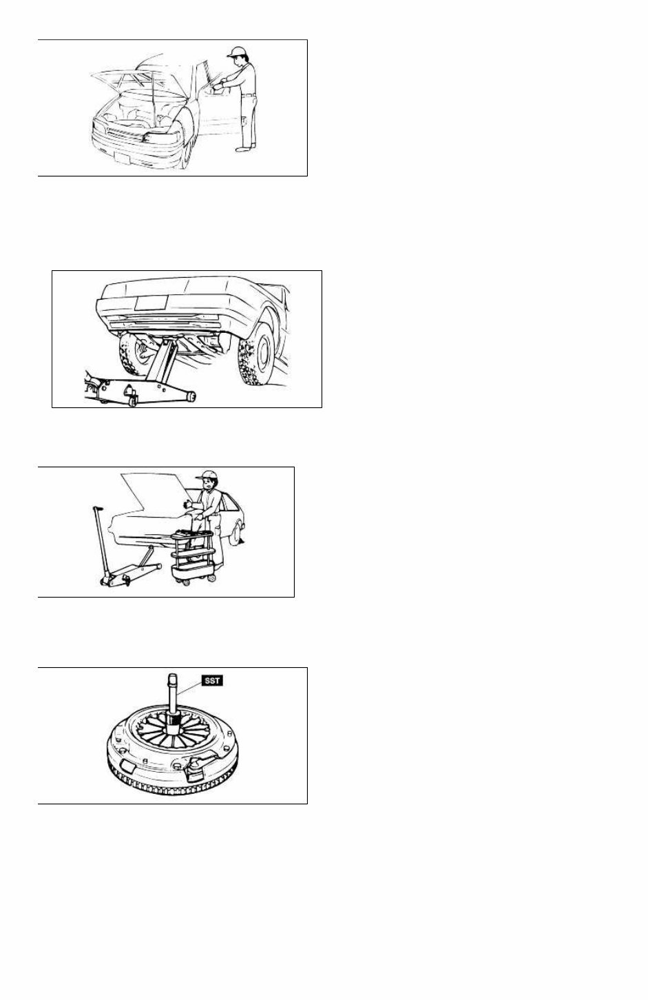
A word about safety The following precautions must be followed when jacking up the vehicle: 1. Block the wheels. 2. Use only the specified jacking positions. 3. Support the vehicle with safety stands. The engine compartment must be clear of tools and people before starting the engine. Preparation of tools and measuring equipment All necessary tools and measuring equipment should be available before starting any work. Special service tools (SST's) Use special service tools when they are required. SST's can be found under "preparation" prior to any procedure requiring them. Removal of parts Begin work only after first learning which parts and subassemblies must be removed and disassembled for replacement or repair. Page 2 of 15 tomsn048@gmail.com
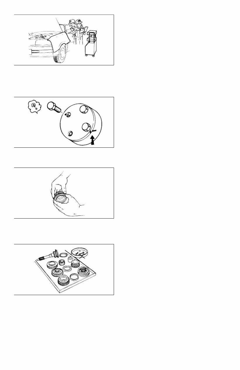
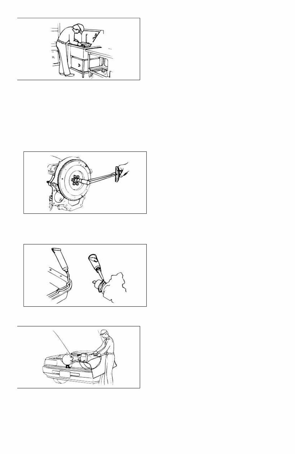
Disassembly If the disassembly procedure is complex, requiring many parts to be disassembled, all parts should be disassembled in a way that will not affect their performance or external appearance. Additionally, these parts should be identified so that reassembly can be done easily and efficiently. Inspection of parts When removed, each part should be carefully inspected for malfunction, deformations, damage, or other problems. Arrangement of parts All disassembled parts should be carefully arranged for reassembly. Separate or otherwise identify the parts to be replaced from those that will be reused. Cleaning parts for reuse All parts that will be reused should be carefully and thoroughly cleaned using appropriate methods. Page 3 of 15 tomsn048@gmail.com
Reassembly Standard values, such as torques and certain adjustments, must be strictly observed in the reassembly of all parts. If removed, the following parts should be replaced with new ones: 1. Oil seals 2. O-rings 3. Cotter pins 4. Gaskets 5. Lock washers 6. Nylon nuts Depending on location: 1. Sealant should be applied or new gaskets installed. 2. Oil should be applied to the moving components of parts. 3. Specified oil or grease should be applied at the appropriate locations (such as oil seals) before reassembly. Adjustments Use appropriate gauges and/or testers when making adjustments. Rubber parts and tubing Prevent gasoline or oil from contacting rubber parts or tubing. Page 4 of 15 tomsn048@gmail.com
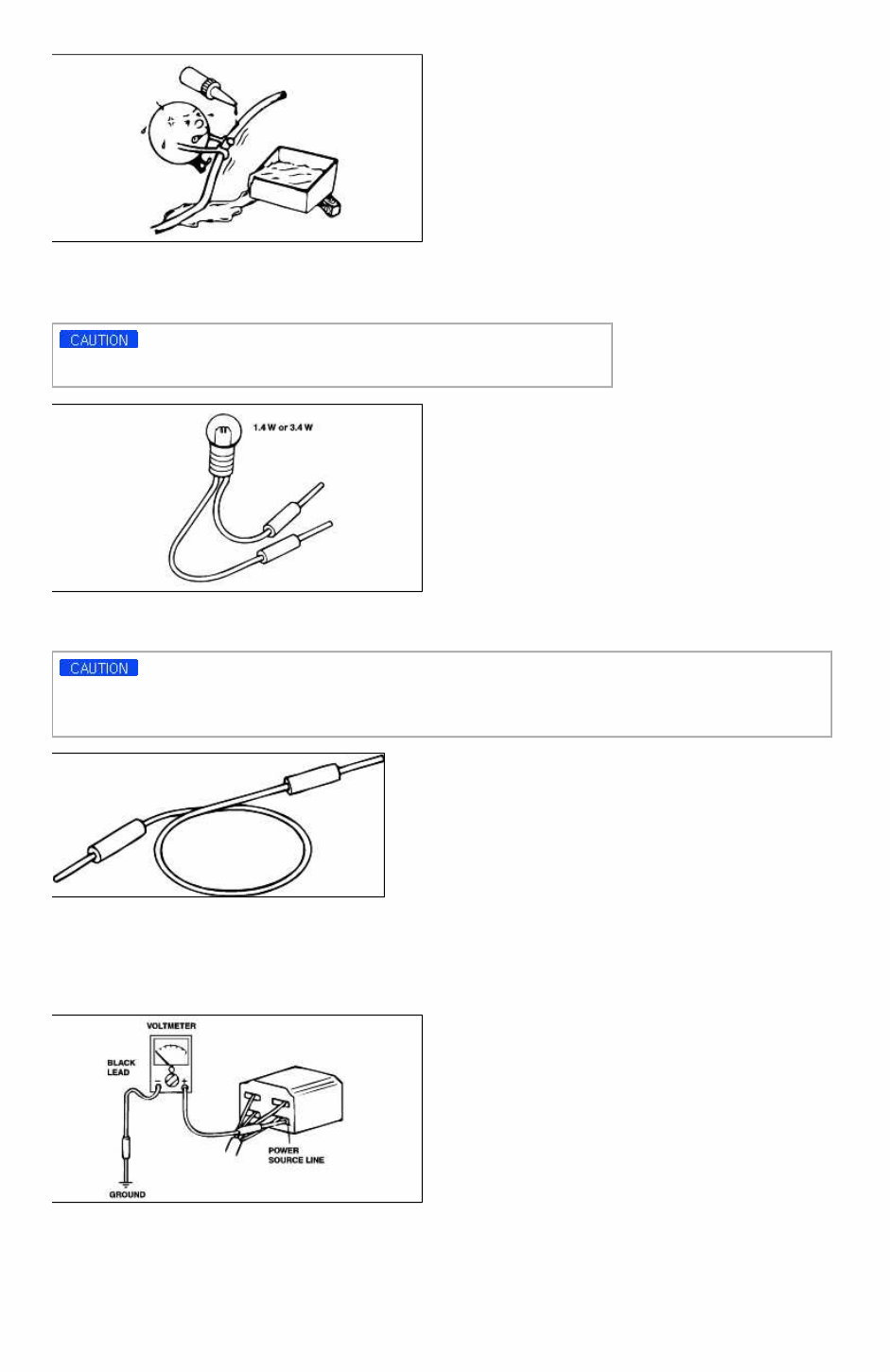
Electrical troubleshooting tools (Test Light) The test light, as shown in figure, uses a 12V bulb. The two lead wires should be connected to probes. The test light is used for simple voltage checks and in checking for short circuits. When checking the engine control module (ECM), never use a bulb exceeding 3.4W. Electrical troubleshooting tools(Jumper wire) The jumper wire is used for testing by shorting across switch terminals and ground connections. Do not connect a jumper wire from the power source line to a body ground. Such a connection may cause damage to harnesses or electronic components. Electrical troubleshooting tools(Voltmeter) The DC voltmeter measures circuit voltage. A voltmeter with a range of 15V or more is used by connecting the positive (+) probe (red lead wire) to the point where voltage is to be measured, and the negative (-) probe (black lead wire) to a body ground. Electrical troubleshooting tools(Ohmmeter) The ohmmeter is used to measure the resistance between two points in a circuit and also to check for continuity and the diagnosis of short circuits. Page 5 of 15 tomsn048@gmail.com
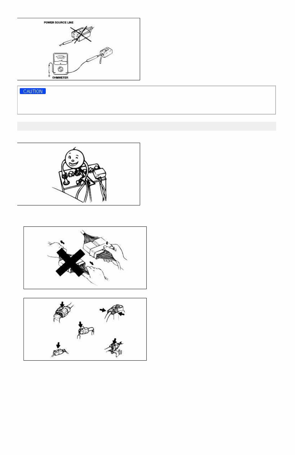
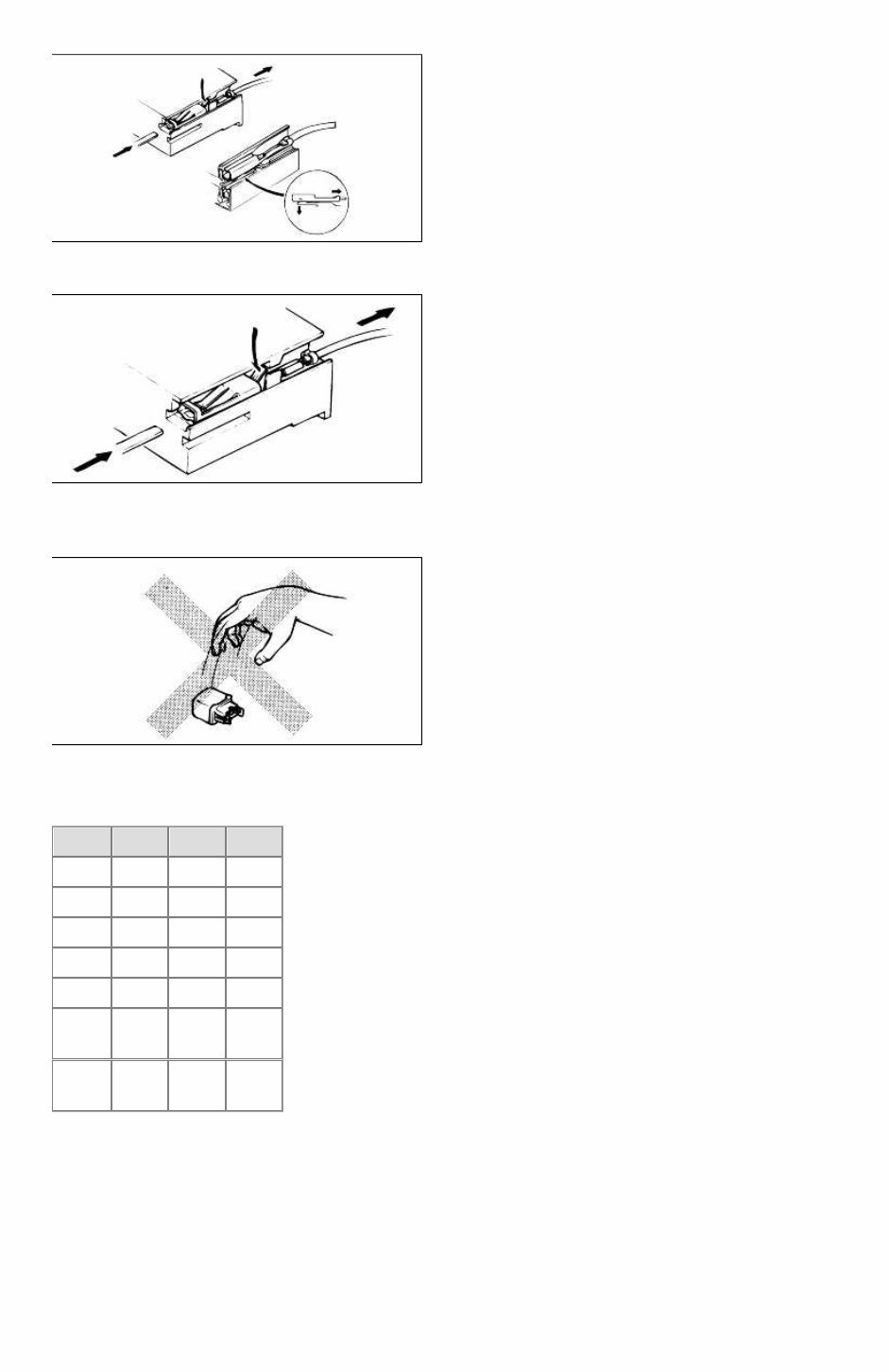
Do not attempt to connect the ohmmeter to any circuit in which voltage is applied. Such a connection may damage the ohmmeter. Electrical parts Battery cable Before disconnecting connectors or replacing electrical parts, disconnect the negative battery cable. Connectors(Removal of connector) 1. Never pull on the wiring harness when disconnecting connectors. 2. Connectors can be removed by pressing or pulling lock lever. Connectors(Locking a connector) Listen for a click when locking connectors. This sound indicates that they are securely locked. Page 6 of 15 tomsn048@gmail.com
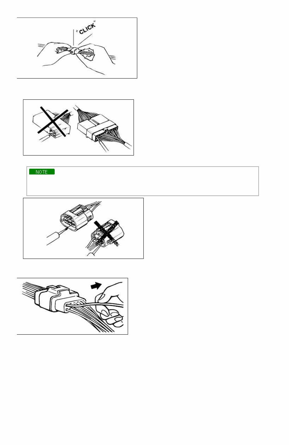
Connectors(Inspection) 1. When a tester is used to check for continuity or to measure voltage, insert tester probe from wire harness side. 2. Check terminals of waterproof connectors from connector side because they cannot be accessed from harness side. • Use a fine wire to prevent damage to the terminal. • Do not damage the terminal when inserting the tester lead. Terminals(Inspection) Pull lightly on individual wires to ensure that they are secured in the terminal. Terminals(Replacement of terminals) Use appropriate tools to remove terminal as shown. When installing the terminal, insert it until it locks securely. Insert a thin piece of metal from the terminal side of the connector, and then, with the terminal locking tab pressed down, pull the terminal out of the connector. Page 7 of 15 tomsn048@gmail.com
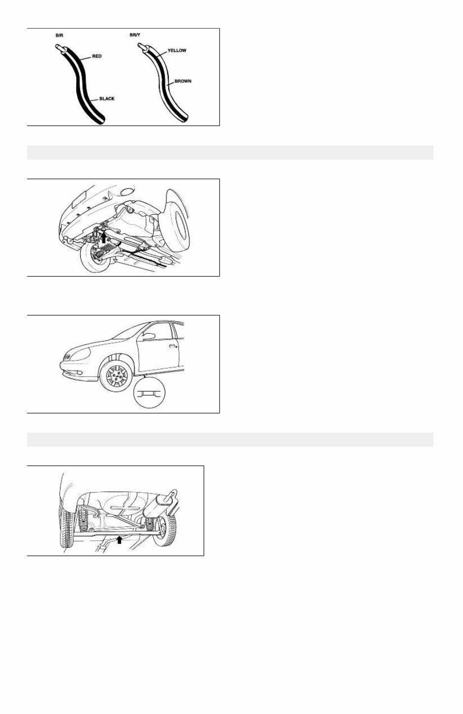
Follow the same procedure as female-type terminal. Terminals(Sensors, switches, and relays) Always handle sensors, switches, and relays carefully. Do not drop them or accidentally strike them against other parts. Wiring color codes Two-color wires are indicated by a two-color code symbol. The first color indicates the base color of the wire; the second color indicates the color of the stripe. Code Color Code Color B Black O Orange Br Brown P Pink G Green R Red Gr Gray V Violet L Blue W White Lb Light blue Y Yellow Lg Light green Page 8 of 15 tomsn048@gmail.com
Jack and safety stand positions Front end Jack position: At the front subframe Safety stand positions: On both sides of the side sills Jack and safety stand positions Jack position: At the center of the rear crossmember Safety stand positions: On both sides of the side sills Page 9 of 15 tomsn048@gmail.com
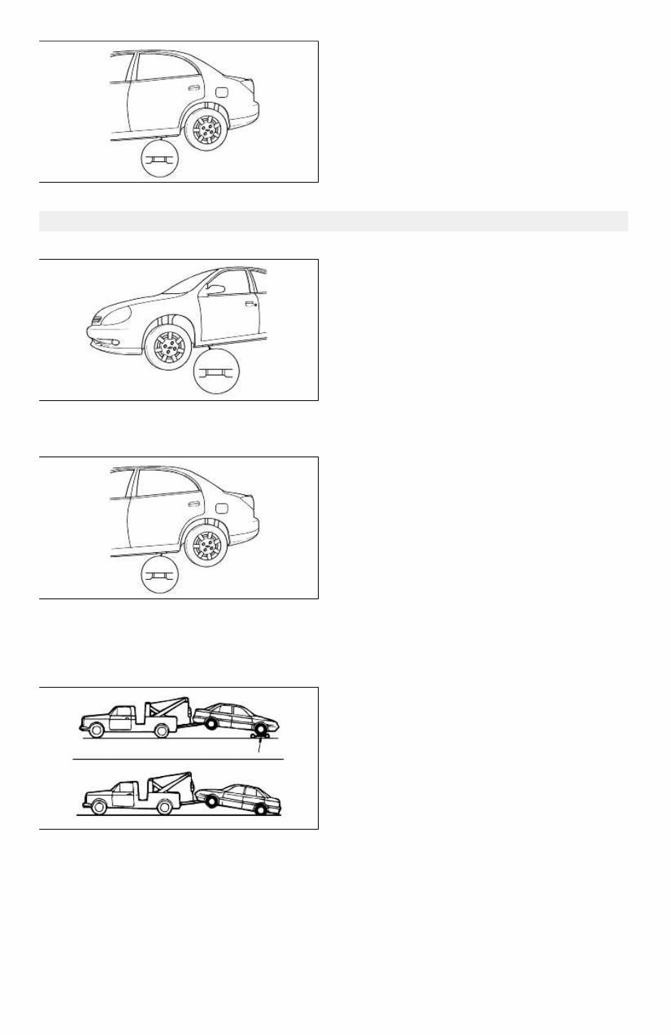
VEHICLE LIFT(2-SUPPORT TYPE) POSITIONS Front end Side sills(both sides) Rear end Side sills(both sides) Towing Proper towing equipment is necessary to prevent damage to the vehicle. Always observe laws and regulations applicable to vehicles in tow. As a general rule, towed vehicles should be pulled with the driving wheels off the ground. If excessive damage or other conditions prevent towing the vehicle with the driving wheels off the ground, use wheel dollies. With either automatic or manual transmission: 1. Set the ignition switch in the ACC position. 2. Place the selector lever or shift lever in N (Neutral). Page 10 of 15 tomsn048@gmail.com
You're Reading a Preview
What's Included?
Lifetime Access
Fast Download Speeds
Online & Offline Access
Access PDF Contents & Bookmarks
Full Search Facility
Print one or all pages of your manual
$33.99
2003 Kia Rio (BC) G 1.6 DOHC Engine Service & Repair Manual
This is the complete factory service repair manual for the KIA RIO (BC) 2003 G 1.6 DOHC ENGINE. This Service Manual has easy-to-read text sections with top quality diagrams and instructions. They are specifically written for the do-it-yourself as well as the experienced mechanic. With step by step instruction & highly detailed exploded pictures & diagrams to show you how to complete the required job correctly & efficiently. Using KIA RIO (BC) 2003 G 1.6 DOHC ENGINE Service Repair Workshop Manual covers every single detail on your machine.
This KIA RIO (BC) 2003 G 1.6 DOHC ENGINE repair manual is an inexpensive way to keep your vehicle working properly.
Models Covers:
KIA RIO (BC) 2003 G 1.6 DOHC ENGINE
Service Repair Manual Covers:
General information
Periodic maintenance
Engine
Fuel system and throttle body
Cooling and lubrication system
Chassis
Electrical system
Servicing information
Emission control information
Wiring diagram
.... and more
This professional technical manual contains service, maintenance, and troubleshooting information for your KIA RIO (BC) 2003 G 1.6 DOHC ENGINE, covering All Models/Engines/Trim/Transmissions Types. This top quality KIA RIO (BC) 2003 G 1.6 DOHC ENGINE Workshop Repair Service manual is COMPLETE and INTACT as should be without any MISSING/CORRUPT part or pages. It is the SAME manual used in the local service/repair shop. KIA RIO (BC) 2003 G 1.6 DOHC ENGINE manual is guaranteed to be fully functional to save your precious time.
Immediate access! NO waiting! You will have instant access to your manual! No shipping fee, No waiting nervously for the postal delivery, you can start doing your repairs right away!
PRODUCT DETAILS:
KIA RIO (BC) 2003 G 1.6 DOHC ENGINE
File Format: PDF
Language: English
Printable: Without any restriction
Delivery: Link will appear on the checkout page after payment is complete.
Requirements: Adobe Reader
Buyers can pay for products via PayPal or Credit Card. We accept payments on behalf of our merchants and send payouts once per week. Click on the instant payment button to pay with your PayPal or credit card and you will receive the download link instantly.
Tags:
KIA RIO (BC) 2003 G 1.6 DOHC ENGINE General Information
KIA RIO (BC) 2003 G 1.6 DOHC ENGINE Periodic maintenance
KIA RIO (BC) 2003 G 1.6 DOHC ENGINE Engine
KIA RIO (BC) 2003 G 1.6 DOHC ENGINE Fuel system and throttle body
KIA RIO (BC) 2003 G 1.6 DOHC ENGINE Cooling and lubrication system
KIA RIO (BC) 2003 G 1.6 DOHC ENGINE Chassis
KIA RIO (BC) 2003 G 1.6 DOHC ENGINE Electrical system
KIA RIO (BC) 2003 G 1.6 DOHC ENGINE Servicing information
KIA RIO (BC) 2003 G 1.6 DOHC ENGINE Emission control information
KIA RIO (BC) 2003 G 1.6 DOHC ENGINE Wiring diagram
KIA RIO (BC) 2003 G 1.6 DOHC ENGINE Service Repair Manual
Reviews
Q&A
Recently Viewed
5,521,897Happy Clients
2,594,462eManuals
1,120,453Trusted Sellers
15Years in Business
Price:
Actual Price:
2003 Kia Rio (BC) G 1.6 DOHC Engine Service & Repair Manual


 Lifetime Access




