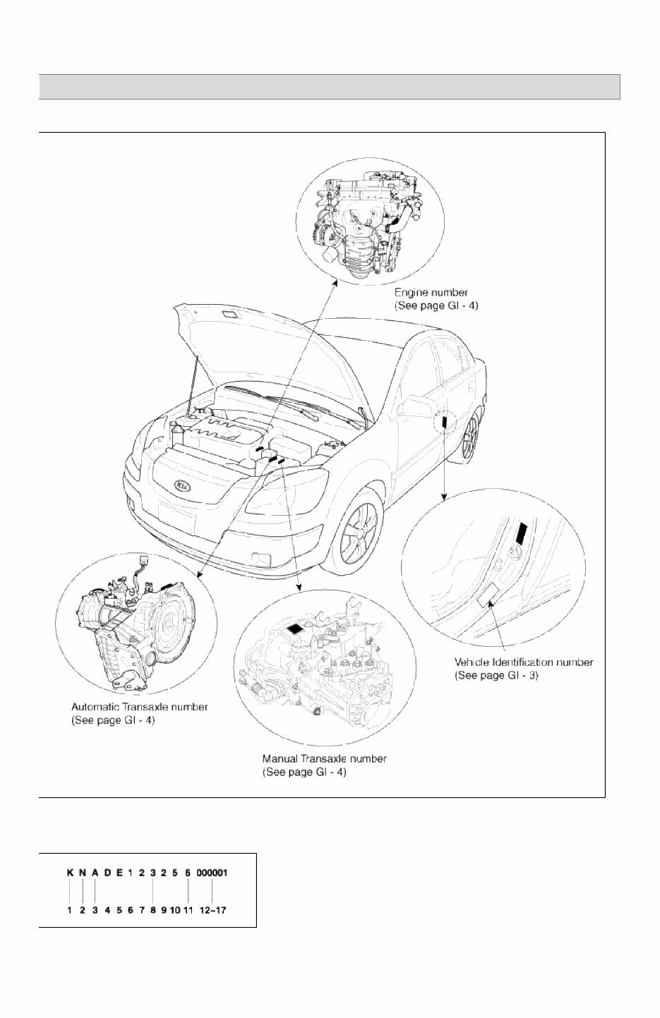
RIO(JB) > 2007 > G 1.6 DOHC > General Information General Information > General Information > General Information IDENTIFICATION NUMBER LOCATIONS IDENTIFICATION NUMBER DESCRIPTION VEHICLE IDENTIFICATION NUMBER 1 - 3 : Make / Vehicle type - KNE, KNA = Kia Passenger Car Page 1 of 24
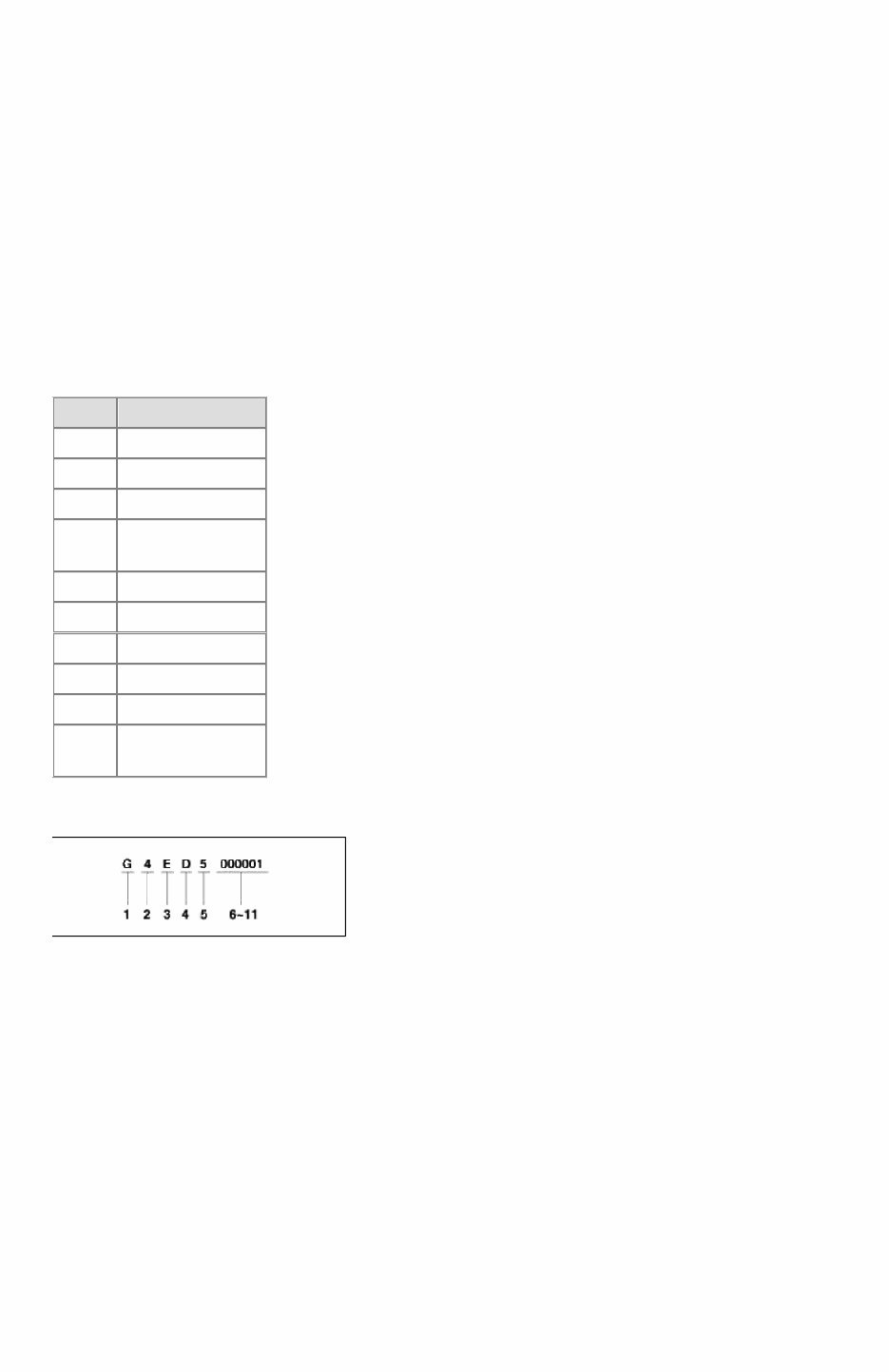
4 - 5 : Vehicle Line / Series - DE = RIO 6 - 7: Body type - 12 = 4 Door Sedan - 16 = 5 Door Hatchback 8 : Engine type - 3 = 1.6 Gasoline (G4ED) 9 : Transaxle type - Check digit 10 : Model year - 5 = 2005, 6 = 2006 11 : Plant location - 6 = Sohari plant 12 : Sequential number - 000001 ~ 999999 PAINT CODE CODE COLOR UD CLEAR WHITE 6C CLEAR SILVER J1 POLAR SILVER J4 CASHMERE BEIGE 2D SOFT GREEN T5 SAPPHIRE 06 SUNSET ORANGE 08 TROPICAL RED 7V OLIVE GRAY 9B MIDNIGHT BLACK ENGINE IDENTIFICATION NUMBER 1. Engine fuel - G = Gasoline 2. Engine range - 4 = 4 cycle 4 cylinder 3. Engine development order - E = ALPHA Engine 4. Engine capacity - D = 1,599cc 5. Production year - 5 : 2005, 6 : 2006 6. Engine production sequence number - 000001 ~ 999999 TRANSMISSION IDENTIFICATION NUMBER MANUAL MANUAL Page 2 of 24
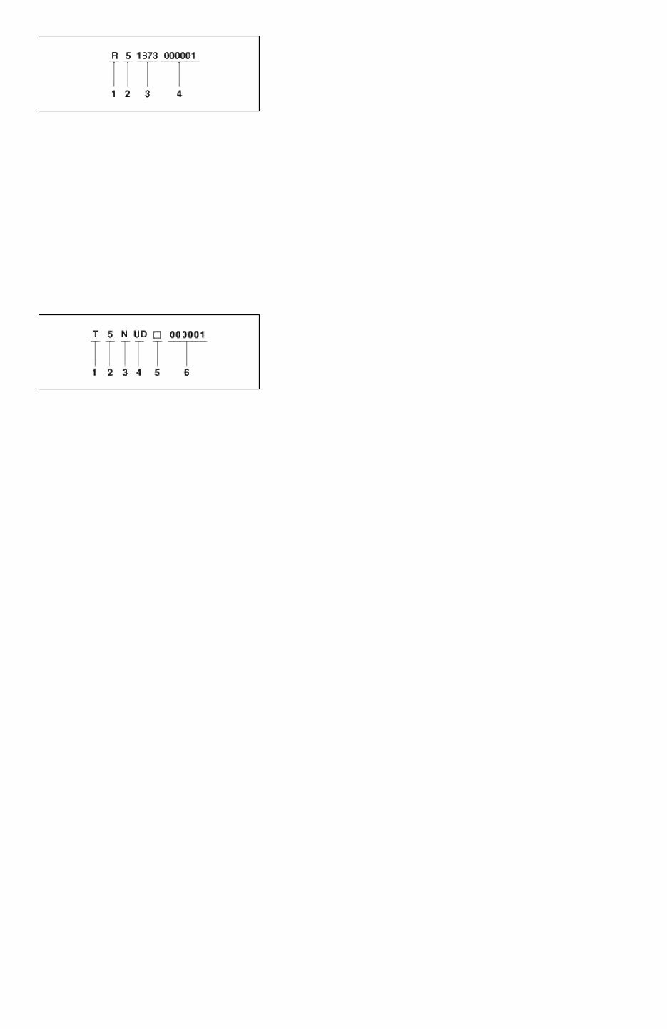
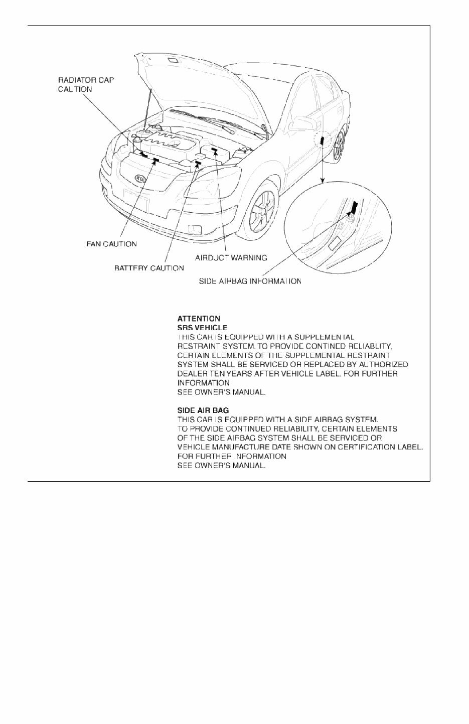
1. Model - R = M5CF1 - P = M5CF2 2. Production year - 5 : 2005, 6 : 2006 3. Gear ratio(Tooth number) <Differential drive gear tooth number / Output shaft gear tooth number> - 1873 = 73/18 = 4.056 4. Transaxle production sequence number - 000001 ~ 999999 AUTOMATIC 1. Modle - T = A4AF3 2. Production year - 5 : 2005, 6 : 2006 3. Gear ratio - N = 4.041 4. Detailed chassification - UD = 1.4 DOHC - WD = 1.6 CVVT 5. Spare 6. Transaxle production sequence number - 000001 ~ 999999 WARNING / CAUTION LABEL LOCATIONS Page 3 of 24
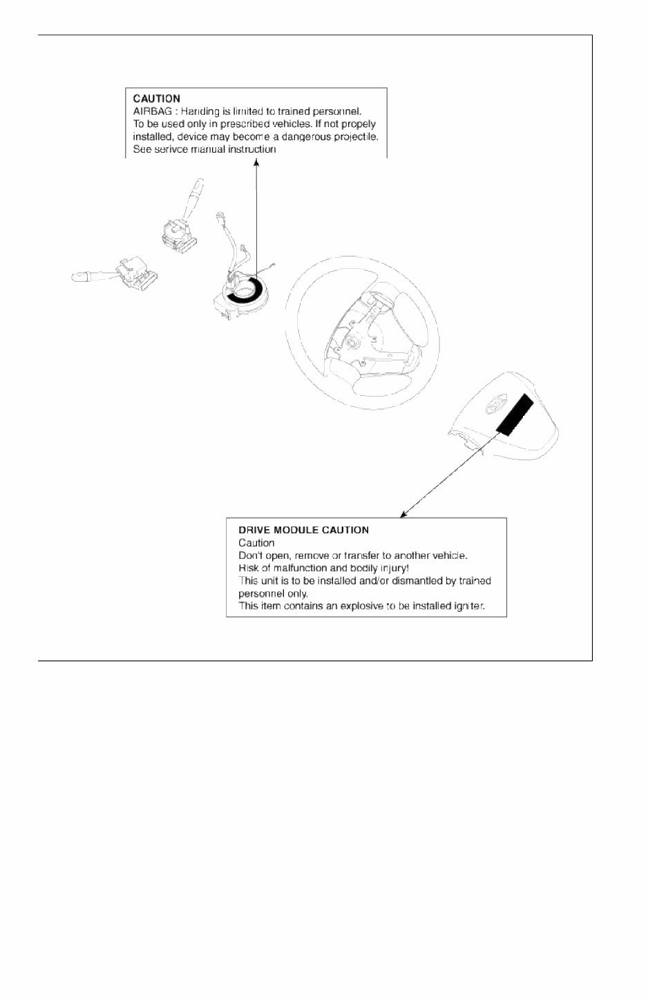
AIR BAG WARNING / CAUTION LABEL Page 4 of 24
AIR BAG WARNING / CAUTION LABEL (CONT’D) Page 5 of 24
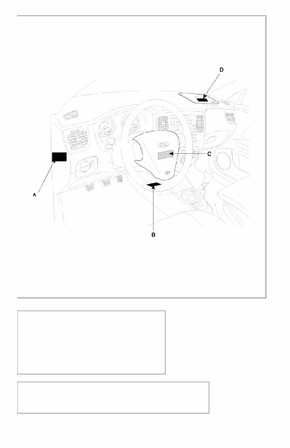
AIR BAG WARNING / CAUTION LABEL (CONT’D) A : WARNING SEE OWNER'S MANUAL. This car is equipped a side airbag for each front seat. • Do not use any accessory seat covers. • Use of other seat covers could reduce the effect of the system. • Do not install any accessories on the side or near the side airbag. • Do not use excessive force on the side of the seal. • For further information, see the owner's manual. B : CAUTION AIRBAG ESPE UNIT Detach connector before unmounting. Assemble strictly according to manual instructions. Page 6 of 24
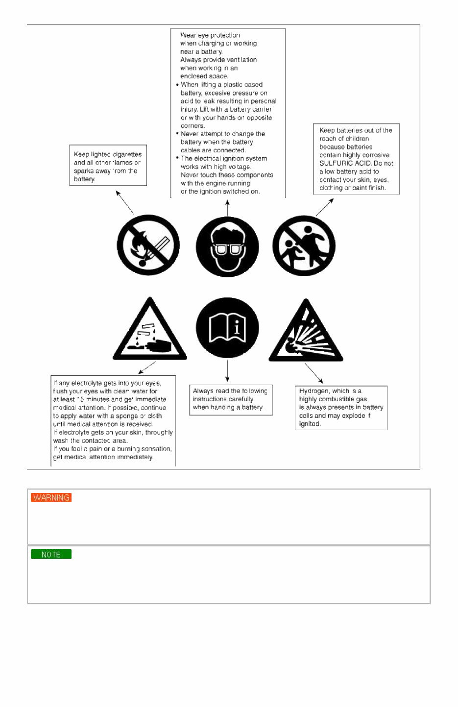
C : PASSENGER MODULE CAUTION CAUTION Don't open, remove or transfer to another vehicle. Risk of malfunction and bodily injury! This unit is to be installed and/or dismantled by trained personnel only. This item contains an explosive to be installed igniter. D : SUPPLEMENTAL RESTRAINT SYSTEM (AIRBAG) INFORMATION • The airbag is a Supplement Restraint System (SRS). You must always wear the seat belts. • The airbag system condition is normal when the "SRS" lamp in the cluster flashes approximately 6 times after the ignition key is turned on and then goes off. • If any of the following condition occur, the system must be serviced. • "SRS" lamp does not light up when the key is turned on. • "SRS" lamp stays lit or flashes continuously. • The airbag has inflated. • The airbag system must be inspected by an authorized dealer ten years after the vehicle manufacture date shown on the certification label, located on left front door opening area. WARNING Failure to the above instructions may result in injury to you or other occupants in the vehicle • See the "SRS" section in Owner's Manual for more information about airbags. BATTERY CAUTION LABEL DESCRIBTION Page 7 of 24
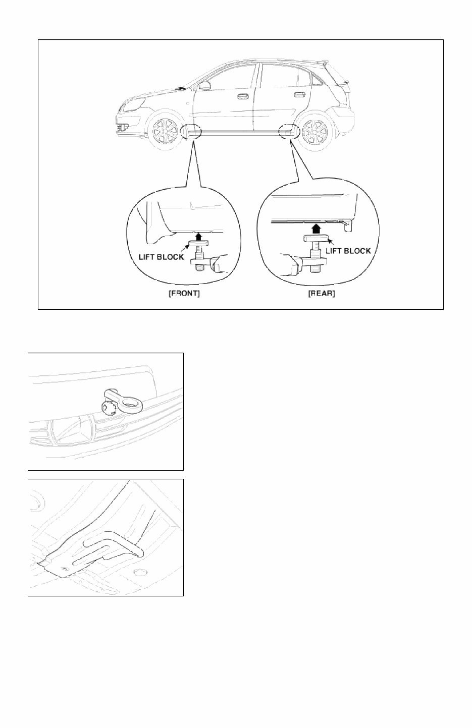
LIFT AND SUPPORT POINTS When heavy rear components such as suspension, fuel tank, spare tire, tailgate and trunk lid are to be removed, place additional weight in the luggage area before hoisting. When substantial weight is removed from the rear of the vehicle, the center of gravity may change and cam cause the vehicle to tip forward on the hoist. • Since each tire/wheel assembly weights approximately 30lbs (14kg), placing the front wheels in the luggage area can assist with the weight distribution. • Use the same support points to support the vehicle on safety stands. 1. Place the lift blocks under the support points as shown in the illustration. 2. Raise the hoist a few inches (centimeters) and rock the vehicle to be sure it is firmly supported. Page 8 of 24
3. Raise the hoist to full height to inspect the lift points for secure support. TOWING If the vehicle needs to be towed, call a professional towing service. Never tow vehicle with just a rope or chain. It is very dangerous. EMERGENCY TOWING There are three propular methods of towing a vehicle : If the vehicle cannot be transported by flat-bed, if should be towed with the front wheels off the ground. If due to damage, the vehicle must be toward with the front wheels on the ground, do not following : Manual Transmission • Release the parking brake. • Shift the transmission to neutral. Page 9 of 24
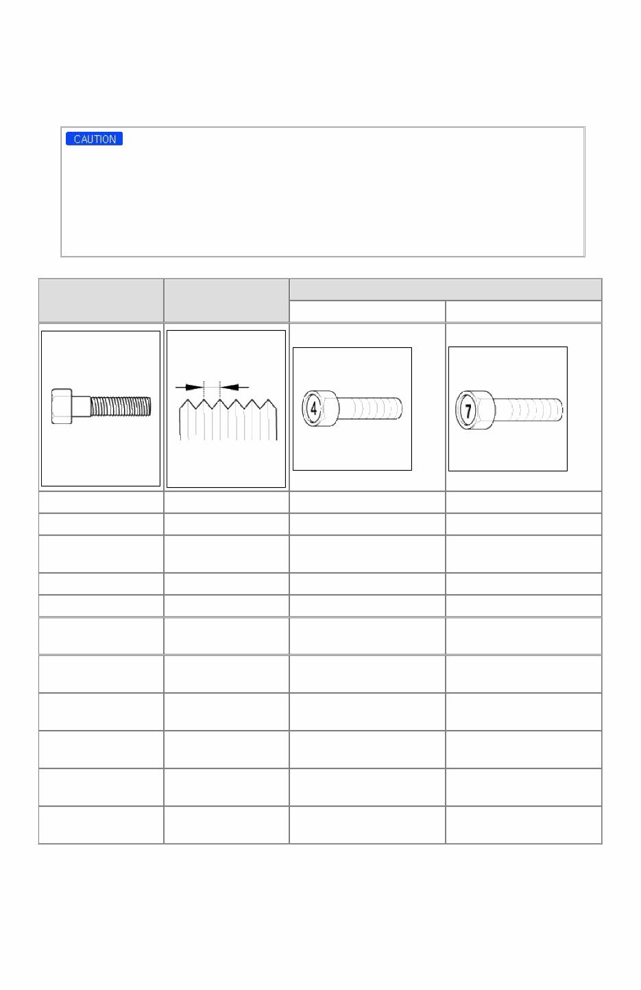
Automatic Transmission • Release the parking brake. • Start the engine. • Shift to [D] position, then [N] position. • Turn off the engine. • Improper towing preparation will damage the transmission. Follow the above procedure exactly. If you cannot shift the transmission or start the engine (automatic transmission), your vehicle must be transported on a flatbed. • It is the best to tow vehicle no farther than 19miles (30km), and keep the speed below 30mph (50km/h). • Trying to lift or tow your vehicle by the bumpers will cause serious damage. The bumpers are not designed to support the vehicle's weight. TIGHTENING TORQUE TABLE OF STANDARD PARTS Bolt nominal diameter (mm) Pitch (mm) Torque Nm (kg.cm, lb.ft) Head Mark 4 Head Mark 7 M5 0.8 3 ~ 4 (30 ~ 40, 2.2 ~ 2.9) 5 ~ 6 (50 ~ 60, 3.6 ~ 4.3) M6 1.0 5 ~ 6 (50 ~ 60, 3.6 ~ 4.3) 9 ~ 11 (90 ~ 110, 6.5 ~ 8.0) M8 1.25 12 ~ 15 (120 ~ 150, 9 ~ 11) 20 ~ 25 (200 ~ 250, 14.5 ~ 18.0 ) M10 1.25 25 ~ 30 (250 ~ 300, 18 ~ 22) 30 ~ 50 (300 ~ 500, 22 ~ 36) M12 1.25 35 ~ 45 (350 ~ 450, 25 ~ 33) 60 ~ 80 (600 ~ 800, 43 ~ 58) M14 1.5 75 ~ 85 (750 ~ 850, 54 ~ 61) 120 ~ 140 (1,200 ~ 1,400, 85 ~ 100) M16 1.5 110 ~ 130 (1,100 ~ 1,300, 80 ~ 94) 180 ~ 210 (1,800 ~ 2,100, 130 ~ 150) M18 1.5 160 ~ 180 (1,600 ~ 1,800, 116 ~ 130) 260 ~ 300 (2,600 ~ 3,000, 190 ~ 215) M20 1.5 220 ~ 250 (2,200 ~ 2,500, 160 ~ 180) 360 ~ 420 (3,600 ~ 4,200, 260 ~ 300) M22 1.5 290 ~ 330 (2,900 ~ 3,300, 210 ~ 240) 480 ~ 550 (4,800 ~ 5,500, 350 ~ 400) M24 1.5 360 ~ 420 (3,600 ~ 4,200, 260 ~ 300) 610 ~ 700 (6,100 ~ 7,000, 440 ~ 505) Page 10 of 24
Fix your car problems with the KIA RIO 2007 Service Manual. This manual provides the information needed to repair your vehicle, catering to both professional mechanics and DIY enthusiasts. It features easy-to-read text sections, high-quality diagrams, and step-by-step instructions for complete disassembly of the machine.
The service manual covers all aspects of the KIA RIO 2007, including maintenance procedures to keep the vehicle in peak operating condition. With instant access and no shipping fees, you can start your repairs immediately without any waiting time.
Product Details:
File Format: PDF
Language: English
Specifications: Full Printable
Zoom IN/OUT: YES
Delivery: Instant
Requirements: Adobe Reader & Win
Compatible: All Versions of Windows & Mac
General chapters included in the KIA RIO 2007 service manual:
Introduction
Lubrication & Maintenance
Suspension
Differential & Driveline
Brakes
Clutch
Cooling
Audio/Video
Chime/Buzzer
Electronic Control Modules
Engine Systems
Heated Systems
Horn
Ignition Control
Instrument Cluster
Lamps
Message Systems
Power Systems
Restraint
Speed Control
Vehicle Theft Security
Wipers/Washers
Navigation/Telecommunication
Wiring
Engine
Exhaust System
Frame & Bumpers
Fuel System
Steering
Transmission and Transfer Case
Tires/Wheels
Body
Heating & Air Conditioning
Component and System Index
Emissions Control
The KIA RIO 2007 Service Manual is a valuable resource for anyone looking to maintain or repair their vehicle. It is instantly accessible and requires no special software, making it convenient for all users.