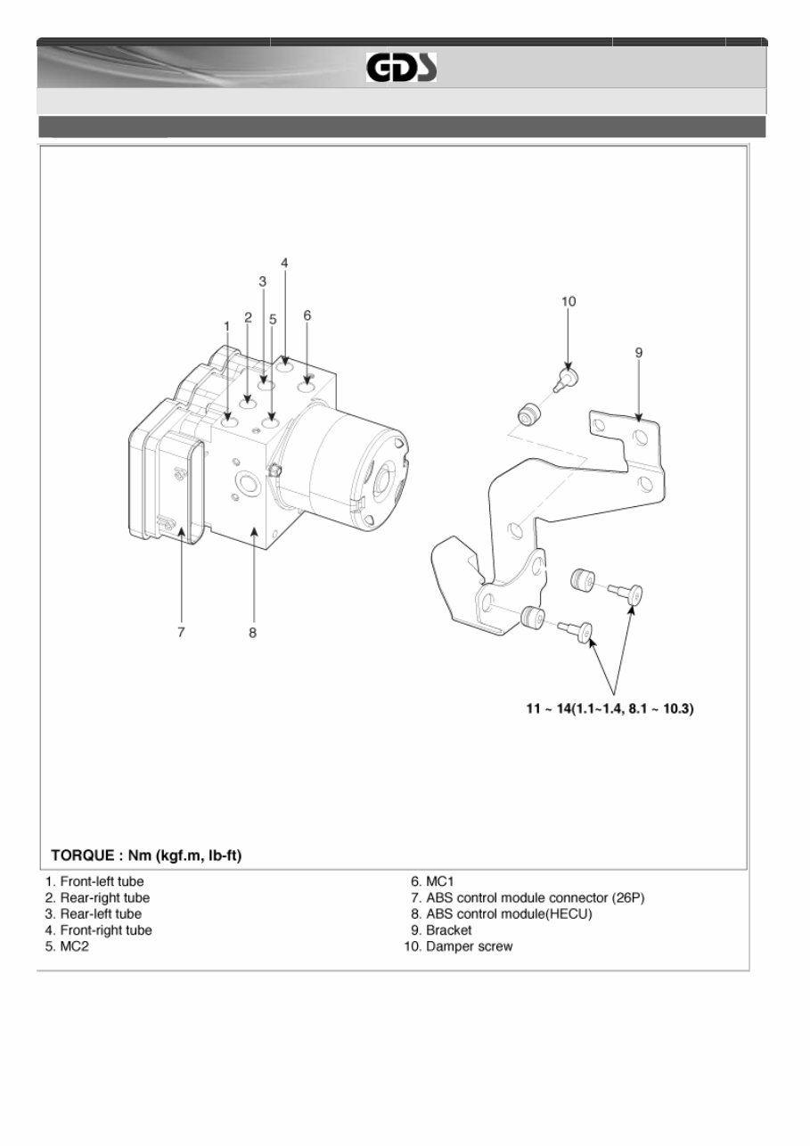
G 1.1 SOHC > Brake System (ABS/ESP(~2009.12.6)) > ABS(Anti-Lock Brake System) > ABS Control Unit > Components and Components Location COMPONENTS 1/1
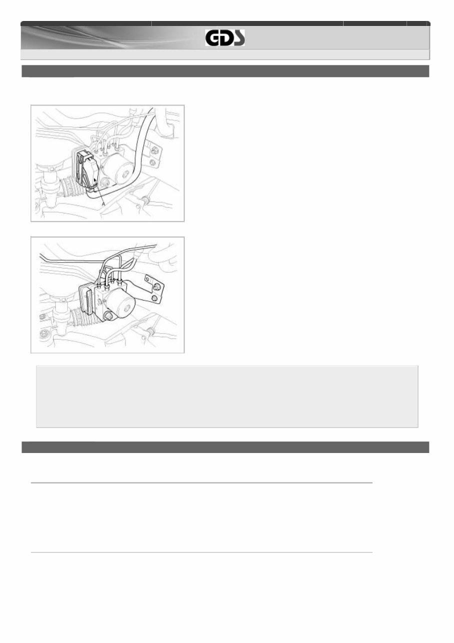
G 1.1 SOHC > Brake System (ABS/ESP(~2009.12.6)) > ABS(Anti-Lock Brake System) > ABS Control Unit > Repair procedures REMOVAL 1 . Turn the ignition switch OFF. 2 . Pull up the lock (A) of the ABS control unit 26P connector , then disconnect the connector. 3 . Disconnect the brake tubes from the HECU by unlocking the nuts counterclockwise with a spanner. 4 . Loosen the 3 ABS HECU bracket bolts, then remove HECU and bracket. 1. Never attempt to disassemble the HECU. 2. The HECU must be transported and stored in. 3. Never shock to the HECU. 5 . Remove the 3 bolts, then remove the bracket from HECU. INSTALLATION 1 . Installation is the reverse of removal. 2 . Tighten the HECU mounting bolts and nuts to the specified torque. Tightening torque HECU bracket nuts : 11 ~ 14 Nm (1.1 ~ 1.4 kgf.m, 8.1 ~ 10.3 Ib-ft) HECU bracket mounting bolt : 16.7 ~ 25.5 Nm (1.7 ~ 2.6 kgf.m, 12.3 ~ 18.8 Ib-ft) 1/1
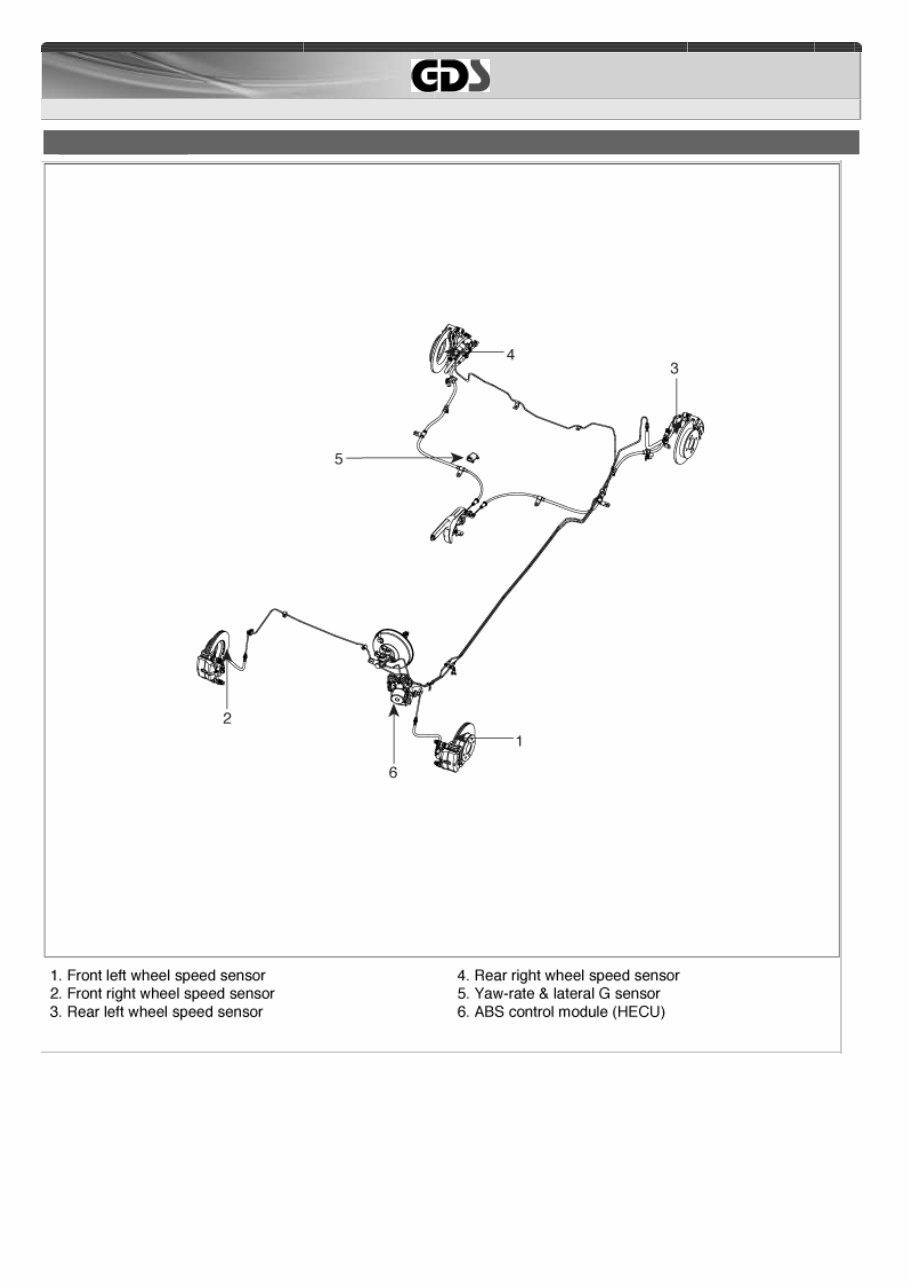
G 1.1 SOHC > Brake System (ABS/ESP(~2009.12.6)) > ABS(Anti-Lock Brake System) > Components and Components Location COMPONENTS 1/1
G 1.1 SOHC > Brake System (ABS/ESP(~2009.12.6)) > ABS(Anti-Lock Brake System) > Description and Operation DESCRIPTION This specification applies to HCU(Hydraulic Control Unit) and ECU(Electronic Control Unit) of the HECU.(Hydraulic and Electronic Control Unit) This specification is for the wiring design and installation of ABS/ESP ECU. This unit has the functions as follows. - Input of signal from Pressure sensor, Steering angle sensor, Yaw & Lateral G sensor,the wheel speed sensors attached to each wheel. - Control of braking force / traction force / yaw moment . - Failsafe function. - Self diagnosis function. - Interface with the external diagnosis tester. Installation position : engine compartment - Brake tube length from Master cylinder port to HECU inlet port should be max. 1m - The position should not be close to the engine block and not lower than the wheel. OPERAT ION The ECU shall be put into operation by switching on the operating voltage (IGN). On completion of the initialization phase, the ECU shall be ready for operation . In the operating condition , the ECU shall be ready, within the specified limits (voltage and temperature ), to process the signals offered by the various sensors and switches in accordance with the control algorithm defined by the software and to control the hydraulic and electrical actuators . Wheel Sensor signal processing The ECU shall receive wheel speed signal from the four active wheel sensors . The wheel signals are converted to voltage signal by the signal conditioning circuit after receiving current signal from active wheel sensors and given as input to the MCU. Solenoid Valve Control When one side of the valve coil is connected to the positive voltage that is provided through the valve relay and the other side is connected to the ground by the semiconductor circuit, the solenoid valve goes into operation . The electrical function of the coils are always monitored by the valve test pulse under normal operation conditions . Voltage limits - Overvoltage When overvoltage is detected (above 17 ± 0.5 V), the ECU switches off the valve relay and shuts down the system . When voltage is returned to operating range, the system goes back to the normal condition after the initialization phase. - Undervoltage In the event of undervoltage (below 10V), ABS control shall be inhibited and the warning lamp shall be turned on. When voltage is returned to operating range, the warning lamp is switched off and ECU returns to normal operating mode. Pump Motor Checking 1/7
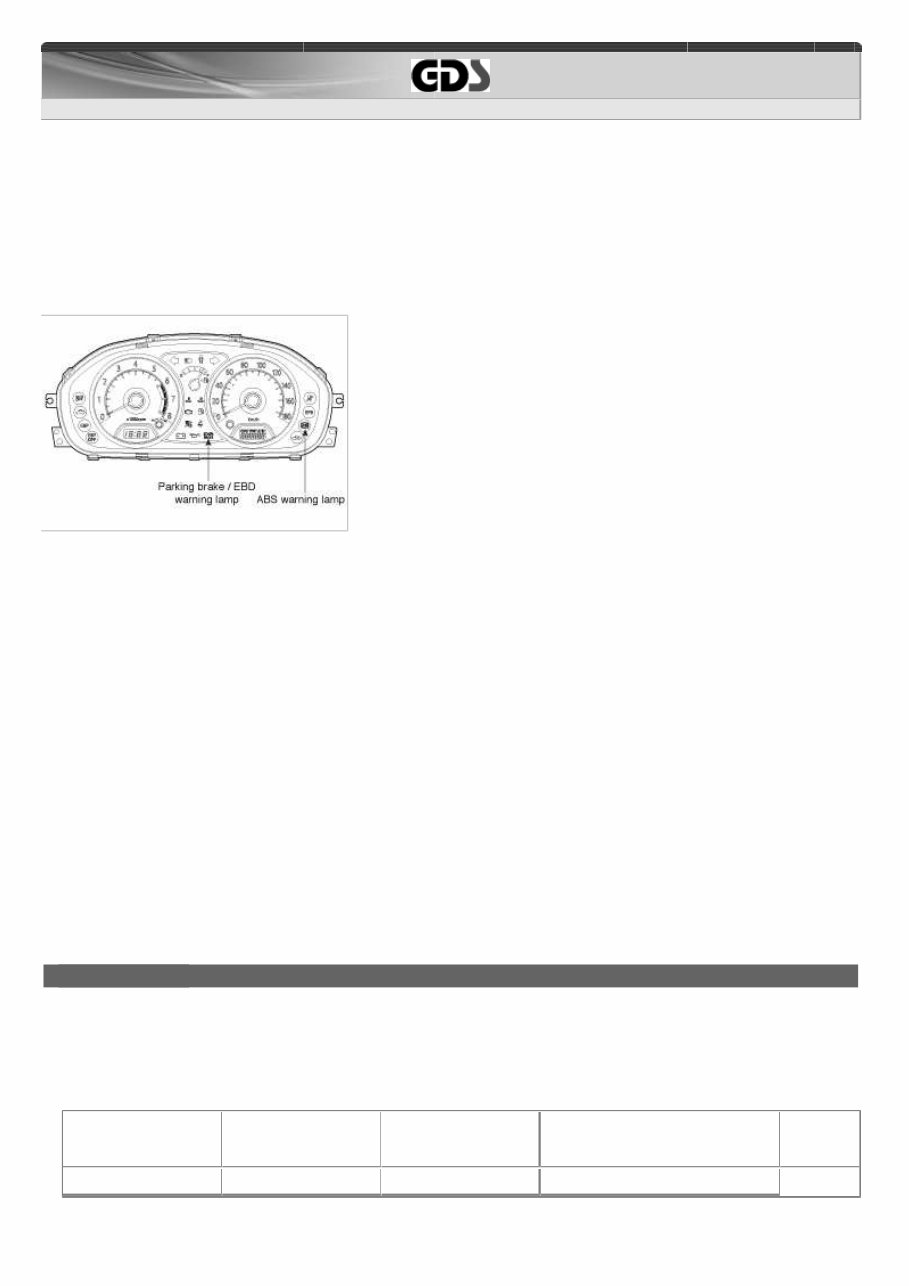
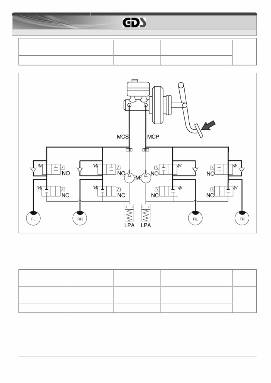
G 1.1 SOHC > Brake System (ABS/ESP(~2009.12.6)) > ABS(Anti-Lock Brake System) > Description and Operation The ECU performs a pump motor test at a speed of 12 km/h(7 MPH) once after IGN is switched on. Diagnostic Interface Failures detected by the ECU are encoded on the ECU, stored in a EEPROM and read out by diagnostic equipment when the ignition switch is turned on. The diagnosis interface can also be used for testing the ECU during production of the ECU and for actuating the HCU in the test line of manufactories (Air-bleeding line or Roll and Brake Test line). WARNING LAMP MODULE 1. ABS Warning Lamp module The active ABS warning lamp module indicates the self-test and failure status of the ABS. The ABS warning lamp shall be on: A. During the initialization phase after IGN ON. (continuously 3 seconds ). B. In the event of inhibition of ABS functions by failure. C. During diagnostic mode. D. When the ECU Connector is seperated from ECU. 2. PARKING /EBD warning lamp module The active EBD warning lamp module indicates the self-test and failure status of the EBD. However, in case the Parking Brake Switch is turned on, the EBD warning lamp is always turned on regardless of EBD functions . The EBD warning lamp shall be on: A. During the initialization phase after IGN ON. (continuously 3 seconds ). B. When the Parking Brake Switch is ON or brake fluid level is low. C. When the EBD function is out of order. D. During diagnostic mode. E. When the ECU Connector is seperated from ECU. ABS CONTROL 1. NORMAL BRAKING without ABS Under the normal braking , voltage is not supplied to solenoid valve, inlet valve is opened and outlet valve is closed .When the brake is depressed , brake fluid is supplied to the wheel cylinder via solenoid valve to activate the brake .When the brake is released , brake fluid is back to the master cylinder via inlet valve and check valve. Solenoid valve State Valve Passage Pump motor 2/7
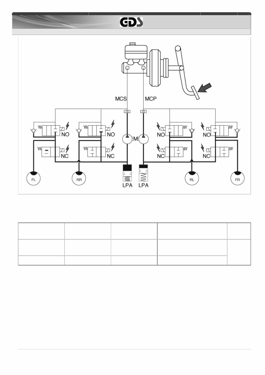
G 1.1 SOHC > Brake System (ABS/ESP(~2009.12.6)) > ABS(Anti-Lock Brake System) > Description and Operation Inlet valve (NO) Outlet valve (NC) OFF OFF Open Close Master cylinder ⇔ Wheel cylinder Wheel cylinder ⇔ Reservoir OFF 2. DUMP MODE Under the emergency braking , if the wheels start to lock up, HECU sends a signal to the solenoid valve to decrease the brake fluid, then voltage is supplied to each solenoid . At this time inlet valve is closed and brake fluid is blocked from the master cylinder. Conversely outlet valve is opened and brake fluid passes through wheel cylinder to reservoir , resulting in pressure decrease . Solenoid Inlet valve (NO) Outlet valve (NC) State ON ON Valve Close Open Passage Master cylinder ⇔ Wheel cylinder Wheel cylinder ⇔ Reservoir Pump motor ON 3/7
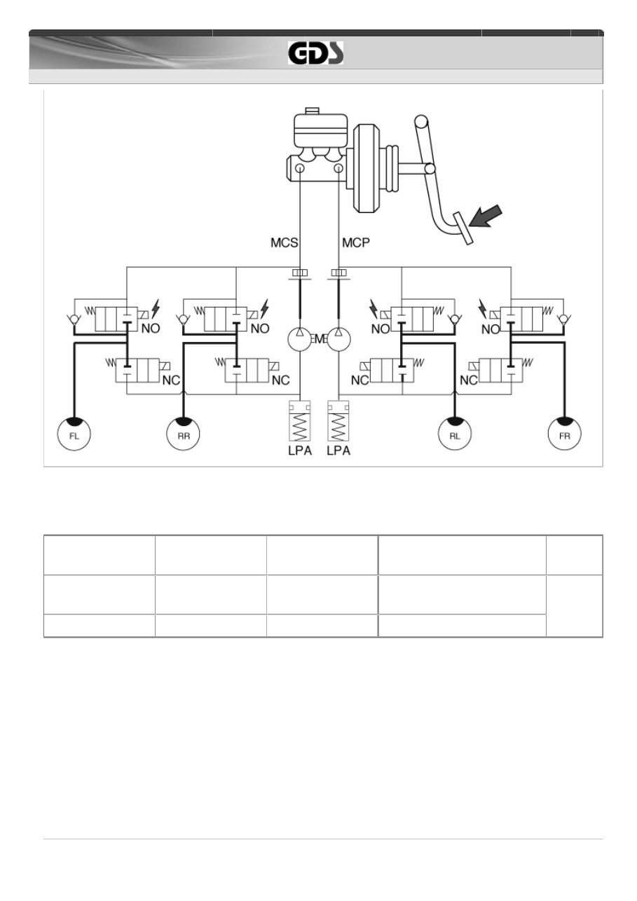
G 1.1 SOHC > Brake System (ABS/ESP(~2009.12.6)) > ABS(Anti-Lock Brake System) > Description and Operation 3. HOLD MODE When the brake fluid pressure is maximally decreased in wheel cylinder, HECU sends a signal to solenoid valve to keep the fluid pressure, voltage is supplied to inlet valve but it is not supplied to outlet valve. At this time inlet and outlet valves are closed and brake fluid is kept in wheel cylinder. Solenoid Inlet valve (NO) Outlet valve (NC) State ON OFF Valve Close Close Passage Master cylinder ⇔ Wheel cylinder Wheel cylinder ⇔ Reservoir Pump motor OFF 4/7
G 1.1 SOHC > Brake System (ABS/ESP(~2009.12.6)) > ABS(Anti-Lock Brake System) > Description and Operation 4. INCREASE MODE If HECU determines there's no lock-up in the wheel, HECU cuts voltage to solenoid valve. So voltage is not supplied to each solenoid valve, brake fluid passes through the inlet valve to wheel cylinder, resulting in pressure increase . Solenoid Inlet valve (NO) Outlet valve (NC) State OFF OFF Valve Open Close Passage Master cylinder ⇔ Wheel cylinder Wheel cylinder ⇔ Reservoir Pump motor ON 5/7
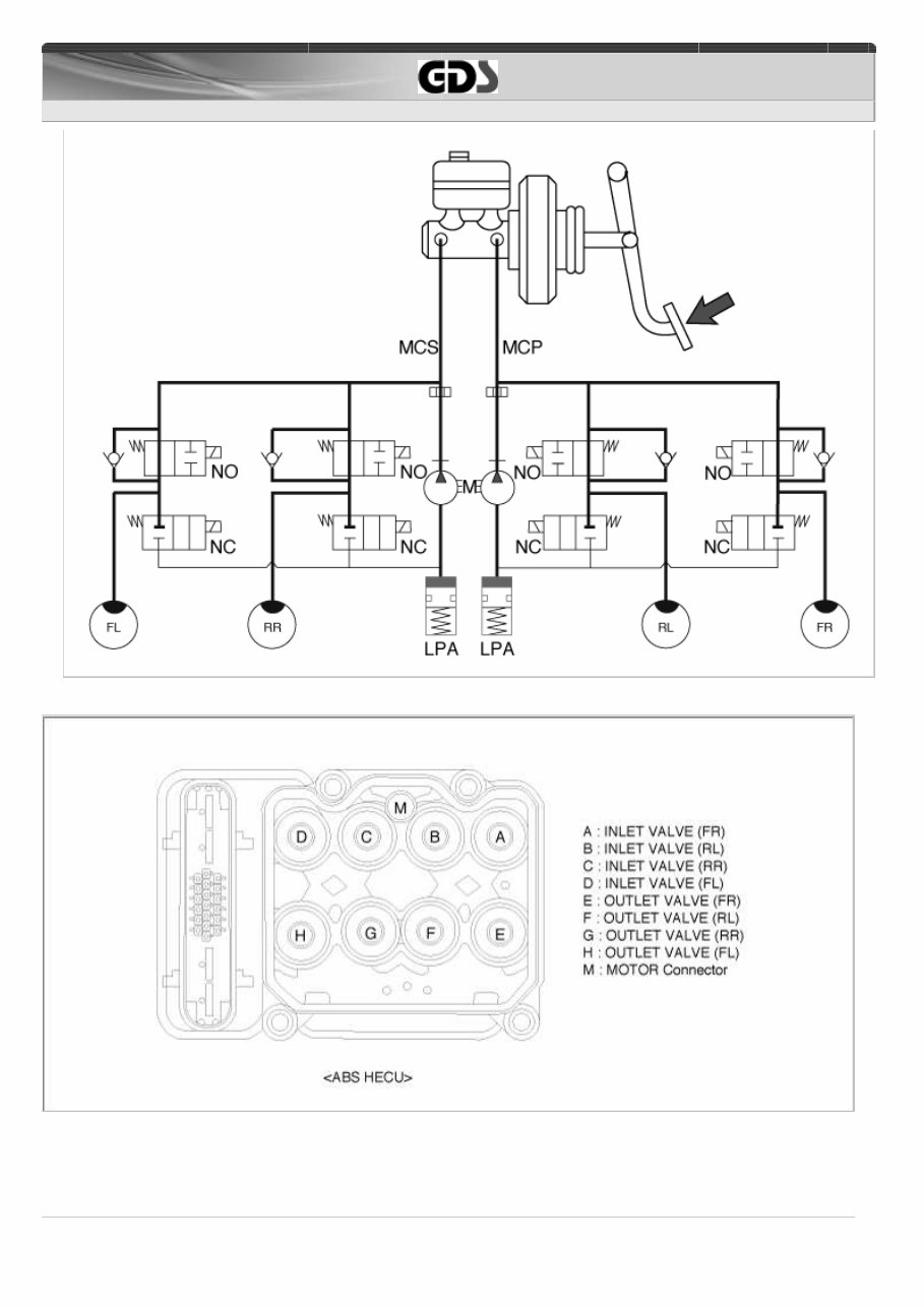
G 1.1 SOHC > Brake System (ABS/ESP(~2009.12.6)) > ABS(Anti-Lock Brake System) > Description and Operation ABS HECU EXTERNAL DIAGRAM HYDRAULIC SYSTEM DIAGRAM 6/7
This is a comprehensive repair manual / service manual for Kia Picanto, covering all models and engines. It is a valuable resource for both professional mechanics and DIY enthusiasts.
The manual allows you to zoom in to view detailed parts and then print out any pages you need, covering in detail the years listed with over 5000 pages for easy, detailed viewing.
Below are the main categories covered in this manual:
ENGINE OVERHAUL AND REBUILDING
BRAKES
SUNROOF
TIMING BELT REPLACEMENT
TROUBLE CODES
WIRING DIAGRAMS
TROUBLESHOOTING AND DIAGNOSTICS
COMPUTER DIAGNOSTIC TROUBLE TREE CHARTS
ENGINE PERFORMANCE
FRONT END AND ALIGNMENT PROCEDURES AND SPECIFICATIONS
SUSPENSION
TRANSMISSION REMOVAL AND INSTALLATION
AIR CONDITIONING SERVICE AND CAPACITIES
TRANSMISSION IN CAR SERVICING
COMPUTER DIAGNOSTIC CODES
FIRING ORDERS
DETAILED SPECIFICATIONS ON EVERY MODEL COVERED
FACTORY MAINTENANCE SCHEDULES AND CHARTS
SERPENTINE BELT ROUTINGS WITH DIAGRAMS
TIMING BELT SERVICE PROCEDURES
BRAKE SERVICING PROCEDURES
DRIVING CONCERNS
COMPLETE TORQUE SPECIFICATIONS
U-JOINT AND CV-JOINT SERVICE PROCEDURES
REPAIR PROCEDURES
COMPLETE WIRING DIAGRAMS
HUNDREDS OF ILLUSTRATIONS
VACUUM DIAGRAMS
AND MORE...
Format: PDF
Language: English
Printable: Yes
Compatible: All Versions of Windows & Mac
Requirements: Adobe Reader
We provide various Service manuals, Workshop Manuals, Repair Manuals, and Owners Manuals for various brands of cars and motorcycles.
This Repair Manual covers the same information that Professional Technicians and Mechanics have. It contains illustrations, diagrams, specifications, step-by-step instructions, pictures, procedures, and much more.
All pages are printable, allowing you to run off what you need and take it with you into the garage or workshop. Save money by doing your own repairs with these very easy to follow, step-by-step instructions!
Instant access means no shipping cost or waiting for a CD to arrive in the mail. You will receive this manual today via instant download on completion of payment via our secure payment processor. We accept all major credit/debit cards and PayPal.