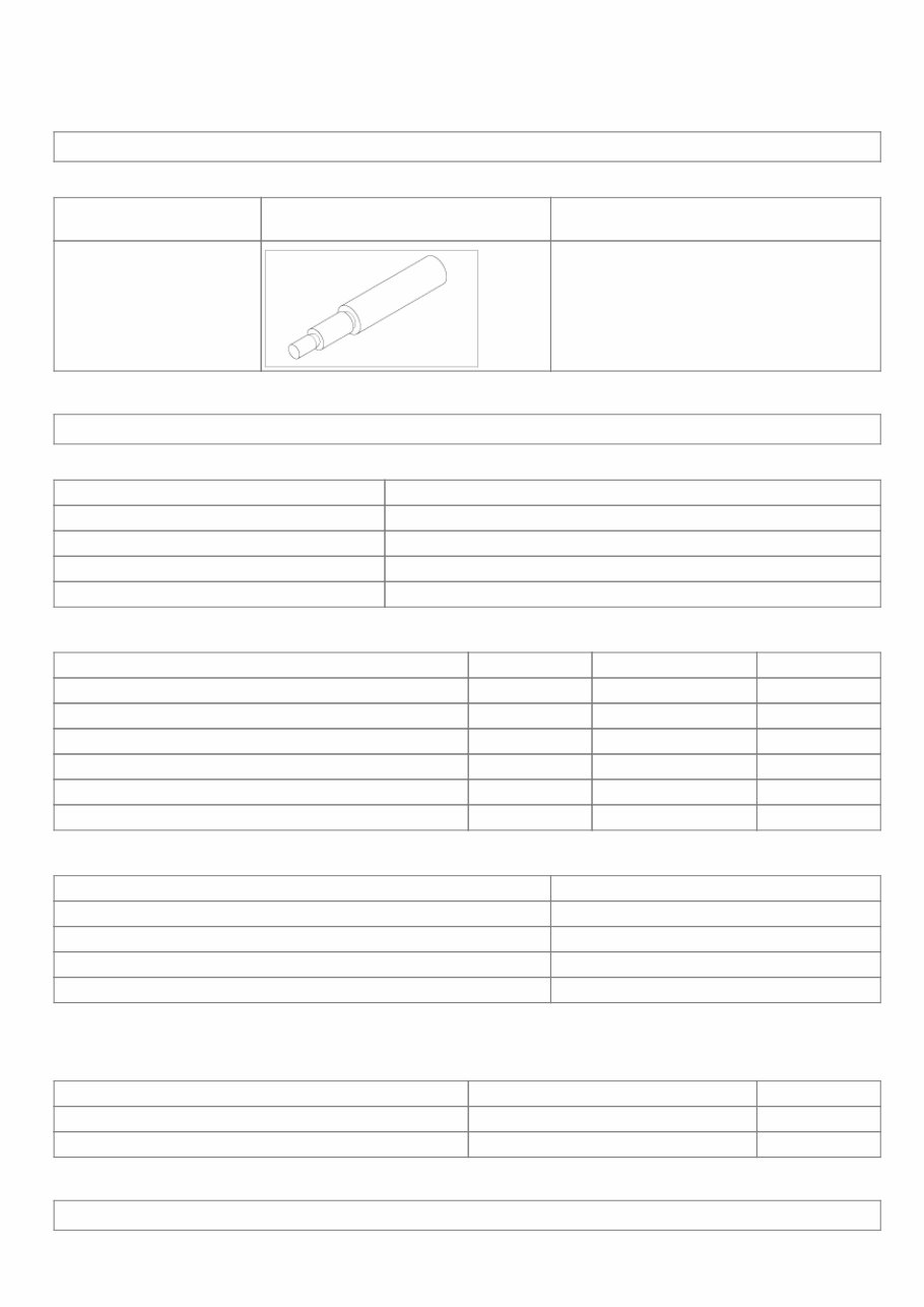
15/05/2012 https://www.kiatechinfo.com/viewer/toc_print.asp?vehicletype=Passenger&mfrcode=KM&area=KM… 1/12 https://www.kiatechinfo.com/viewer/toc_print.asp?vehicletype=Passenger&mfrcode=KM&area=KM… OPTIMA(MG) > 2007 > G 2.4 DOHC > Clutch System Clutch System > General Information > Special Service Tools SPECIAL TOOLS Tool (Number and Name) Illustration Use 09411-11000 Clutch disc guide Installation of the clutch disc Clutch System > General Information > Specifications SPECIFICATION Item SPECIFICATION Engine type 2.4L Clutch operation Hydraulic type Clutch disc Single dry plate with diaphragm spring Clutch cover assembly Self Adjusting Clutch TIGHTENING TORQUE Item Nm Kgf.cm lb-ft Clutch cover (2.4L-9EA) 11.8~14.7 120~150 8.7~10.8 Concentric slave cylinder 11.8~14.7 120~150 8.7~10.8 Stop lamp switch 7.8~9.8 80~100 5.8~7.2 Ignition lock switch 7.8~9.8 80~100 5.8~7.2 Air bleeding plug 24.5~28.4 250~290 18.1~21.0 Clutch pedal mounting 24.5~34.3 250~350 18.1~25.3 SERVICE STANDARD Item Standard value Clutch pedal stroke 145mm (5.7in) Clutch pedal free play 13mm (0.51in) or less Distance between a mat and a clutch pedal 234.7mm (9.2401in) Depth from a clutch lining surface to a rivet 0.3mm (0.0118in) LUBRICANTS Item Specified lubricants Quantity Inner surface of clutch disc spline CASMOLY L9508 0.2 gr. Clutch master cylinder tube RG 306 As required Clutch System > Clutch System > Description and Operation DESCRIPTION
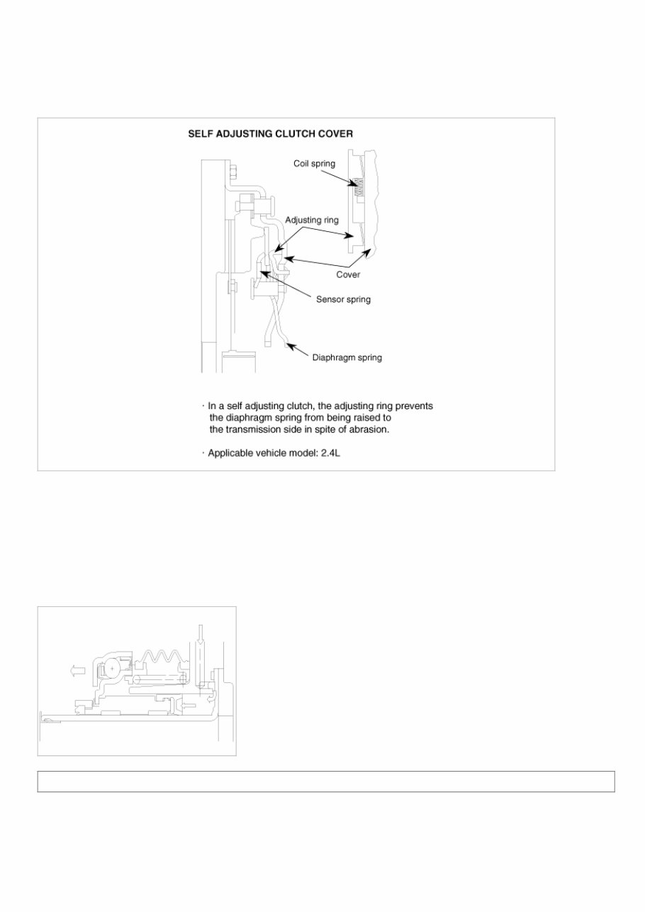
15/05/2012 https://www.kiatechinfo.com/viewer/toc_print.asp?vehicletype=Passenger&mfrcode=KM&area=KM… 2/12 https://www.kiatechinfo.com/viewer/toc_print.asp?vehicletype=Passenger&mfrcode=KM&area=KM… SELF ADJUSTING CLUTCH(S.A.C.) COVER • A self-adjusting clutch cover is used to increase durability, a cover weight is increasing and a clutch pedal pressure can be more needed. • To make up for this defect, the self adjusting clutch system makes the requsted pedal pressure minimized so that makes the maintenance cycle longer. • Applied only in 2.4L gasoline engine vehicles. CONCENTRIC SLAVE CYLINDER-C.S.C. It improves working efficiency and lowers the number and the weight of part by unifing clutch release control parts(clutch release bearing ~ clutch release cylinder) in a manual transaxle. OPERATION CONCENTRIC SLAVE CYLINDER-C.S.C When the clutch pedal is pressed, oil pressure is transmitted along the arrow directions shown below and that moves the clutch slave cylinder and the diaphragm spring of the clutch cover. Clutch System > Clutch System > Repair procedures SERVICE ADJUSTMENT PROCEDURE STOP LAMP SWITCH 1. Disconnect the 2P connector from the stop lamp switch. 2. Remove the stop lamp switch. 3. Check for continuity between the terminals according to the table.
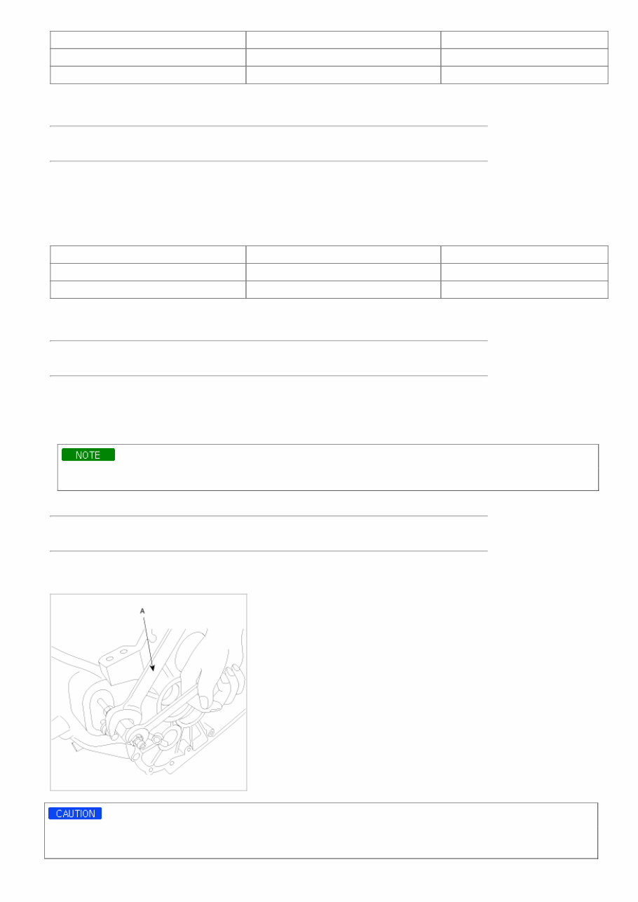
15/05/2012 https://www.kiatechinfo.com/viewer/toc_print.asp?vehicletype=Passenger&mfrcode=KM&area=KM… 3/12 https://www.kiatechinfo.com/viewer/toc_print.asp?vehicletype=Passenger&mfrcode=KM&area=KM… Clutch pedal position Stop lamp switch Continuity Released Pressed YES Pressed Released NO If the continuity is not as specified, replace the stop lamp switch. If OK, install the stop lamp switch and adjust the pedal height. TORQUE : 7.8~9.8Nm (80~100Kgf.cm, 5.8~7.2lb-ft) IGNITION LOCK SWITCH 1. Disconnect 2P-connector from a ignition lock switch. 2. Disconnect the ignition lock switch. (if you can install a tester with the switch fixed, this step can be omissible) 3. Check for continuity between terminals. (refer to the table below) Clutch pedal position Ignition lock switch Continuity Released Released NO Pressed Pressed YES If there is difference between what tested and the table above, replace the ignition lock switch with a new one. If not, install the ignition lock switch and adjust the clutch pedal. TORQUE : 7.8~9.8Nm (80~100Kgf.cm, 5.8~7.2lb-ft) CONCENTRIC SLAVE CYLINDER AIR BLEEDING PROCEDURE 1. After disconnecting a cap from the concentric slave cylinder air bleeder, insert a vinyl hose in the plug. 2. Loosening the plug screw, press and release the clutch pedal about 10 times. Hold the air bleeder body not to rotate with a spanner(A). The holding is needed when the plug loosened or tightened. 3. Tighten the plug during the clutch pedal pressed. Afterwards, raise the pedal with a hand. TORQUE : 24.5~28.4Nm (80~100Kgf.cm, 18.1~21.0lb-ft) 4. After pressing the clutch pedal 3 times more, loosen the plug and retighten it with the pedal pressed. Raise it again, then. 5. Repeat the step 4 two or three times. (until there is no bubble in the fluid) 1. Do not clamp the pipe of a concentric slave cylinder. 2. Be careful not to damage O-rings.
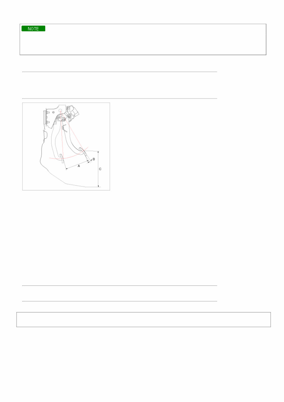
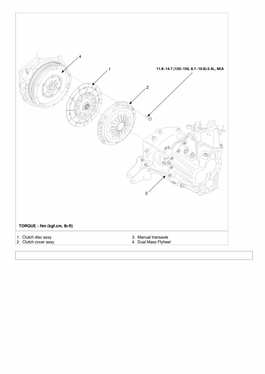
15/05/2012 https://www.kiatechinfo.com/viewer/toc_print.asp?vehicletype=Passenger&mfrcode=KM&area=KM… 4/12 https://www.kiatechinfo.com/viewer/toc_print.asp?vehicletype=Passenger&mfrcode=KM&area=KM… Clutch pedal and Ignition lock switch • Inspect a ignition lock switch. • Remove the driver's seat mat to adjust a clutch pedal. • No gap between a clutch master cylinder pistion and push rod can cause clutch slip. 1. Loosen and draw out the bolt until it is off the pedal surface. 2. Push and pull a clutch master cylinder push rod to satisfy the specification below. Specification: Clutch pedal stroke(A) - 145mm(5.7087in) Clutch pedal free play(B) - 13mm(0.5118in) Clutch pedal distance(C) - 234.7mm(9.2401in) 3. With no pressure on a clutch pedal, tighten the bolt until it contacts on the pedal. 4. Tighten the retaining nut. 5. Press the clutch pedal to the floor. 6. Adjust the ignition lock switch position with the pedal raised(3~5mm). 7. Install the ignition lock switch firmly. TORQUE: 7.8~9.8Nm (80~100Kgf.cm, 5.8~7.2lb-ft) Clutch System > Clutch System > Clutch Cover And Dinode > Components and Components Location COMPONENTS
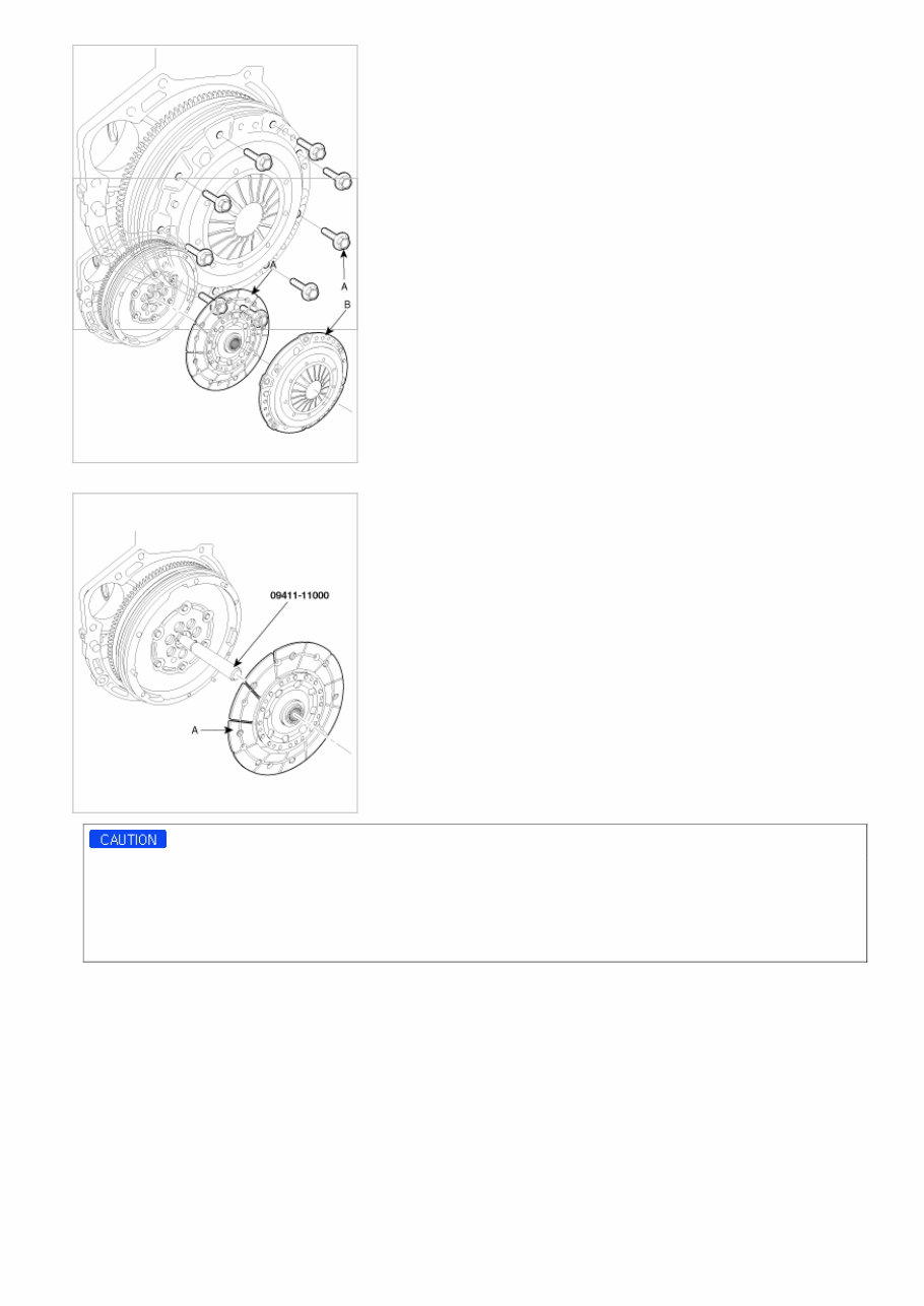
15/05/2012 https://www.kiatechinfo.com/viewer/toc_print.asp?vehicletype=Passenger&mfrcode=KM&area=KM… 5/12 https://www.kiatechinfo.com/viewer/toc_print.asp?vehicletype=Passenger&mfrcode=KM&area=KM… Clutch System > Clutch System > Clutch Cover And Dinode > Repair procedures REPLACEMENT 1. Remove a transaxle assembly (refer to 'MT'-group). 2. Remove the clutch cover bolts(A). Not to be bent or twisted, loosen the bolts in the specified order.
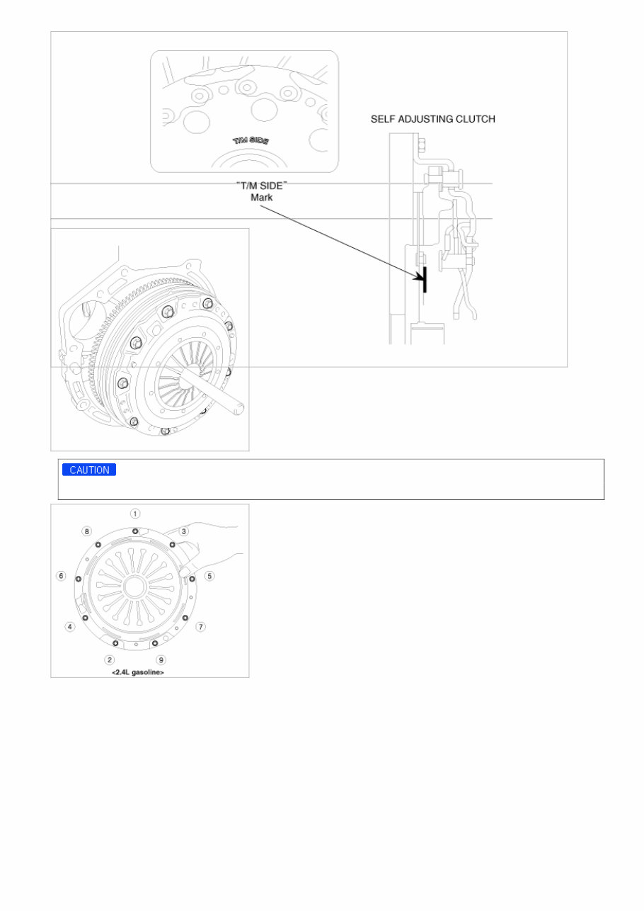
15/05/2012 https://www.kiatechinfo.com/viewer/toc_print.asp?vehicletype=Passenger&mfrcode=KM&area=KM… 6/12 https://www.kiatechinfo.com/viewer/toc_print.asp?vehicletype=Passenger&mfrcode=KM&area=KM… 3. Remove the clutch cover(A) and disc(B). 4. Using the SST(09411-11000), install a disc(A). • On vehicles with 2.4L gasoline engines, replace a clutch cover and disc as a set. • Apply grease on a disc spline part and transmission input shaft spline part as required. → How to do: apply grease(CASMOLY L9508) 0.2gr. on the transmission input shaft spline part. • The 'T/M SIDE' marked surface should face the transaxle. → If the surface face the opposite side, there can be an interference between a disc and a flywheel surface.
15/05/2012 https://www.kiatechinfo.com/viewer/toc_print.asp?vehicletype=Passenger&mfrcode=KM&area=KM… 7/12 https://www.kiatechinfo.com/viewer/toc_print.asp?vehicletype=Passenger&mfrcode=KM&area=KM… 5. Tighten the clutch cover. TORQUE: 11.8~14.7Nm (120~150kgf.cm, 8.7~10.8lb-ft) (2.4L-9EA) When installing the clutch cover, tighen the bolts. INSPECTION 1. Inspect diaphragm spring wear which is in contact with a concentric slave cylinder bearing.
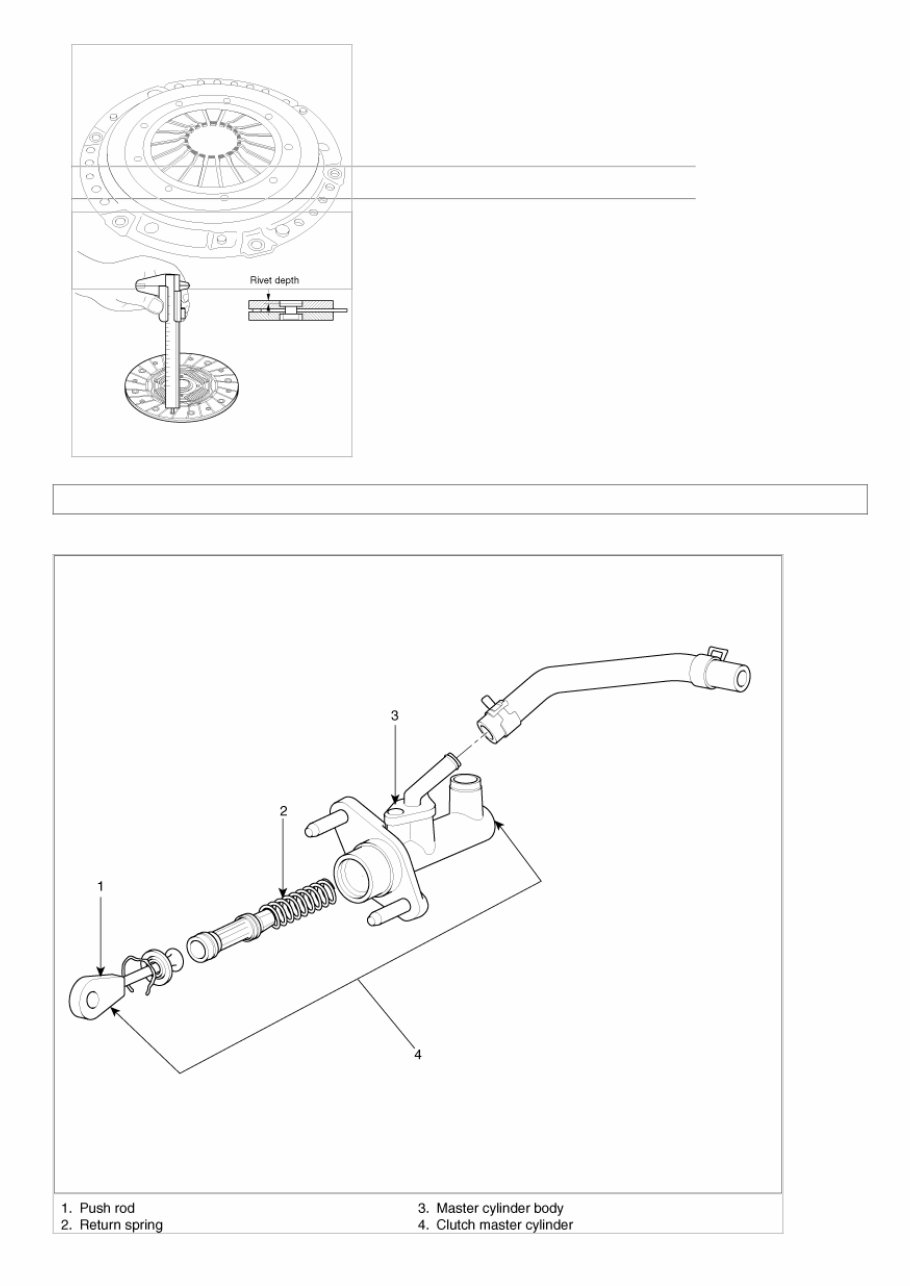
15/05/2012 https://www.kiatechinfo.com/viewer/toc_print.asp?vehicletype=Passenger&mfrcode=KM&area=KM… 8/12 https://www.kiatechinfo.com/viewer/toc_print.asp?vehicletype=Passenger&mfrcode=KM&area=KM… 2. Check the clutch cover and disc surface for wear or crack. 3. Check the clutch disc lining for slipping or oil mark. 4. Measure the depth from a clutch lining surface to a rivet. If the measured value is less than the specification below, replace it. Specification: 0.3mm(0.0118in) Clutch System > Clutch System > Clutch Master Cylinder > Components and Components Location COMPONENETS
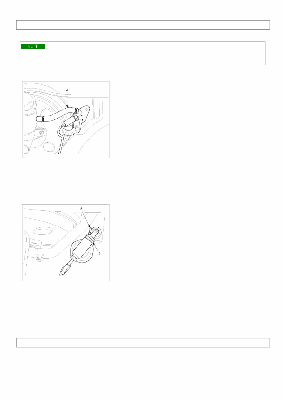
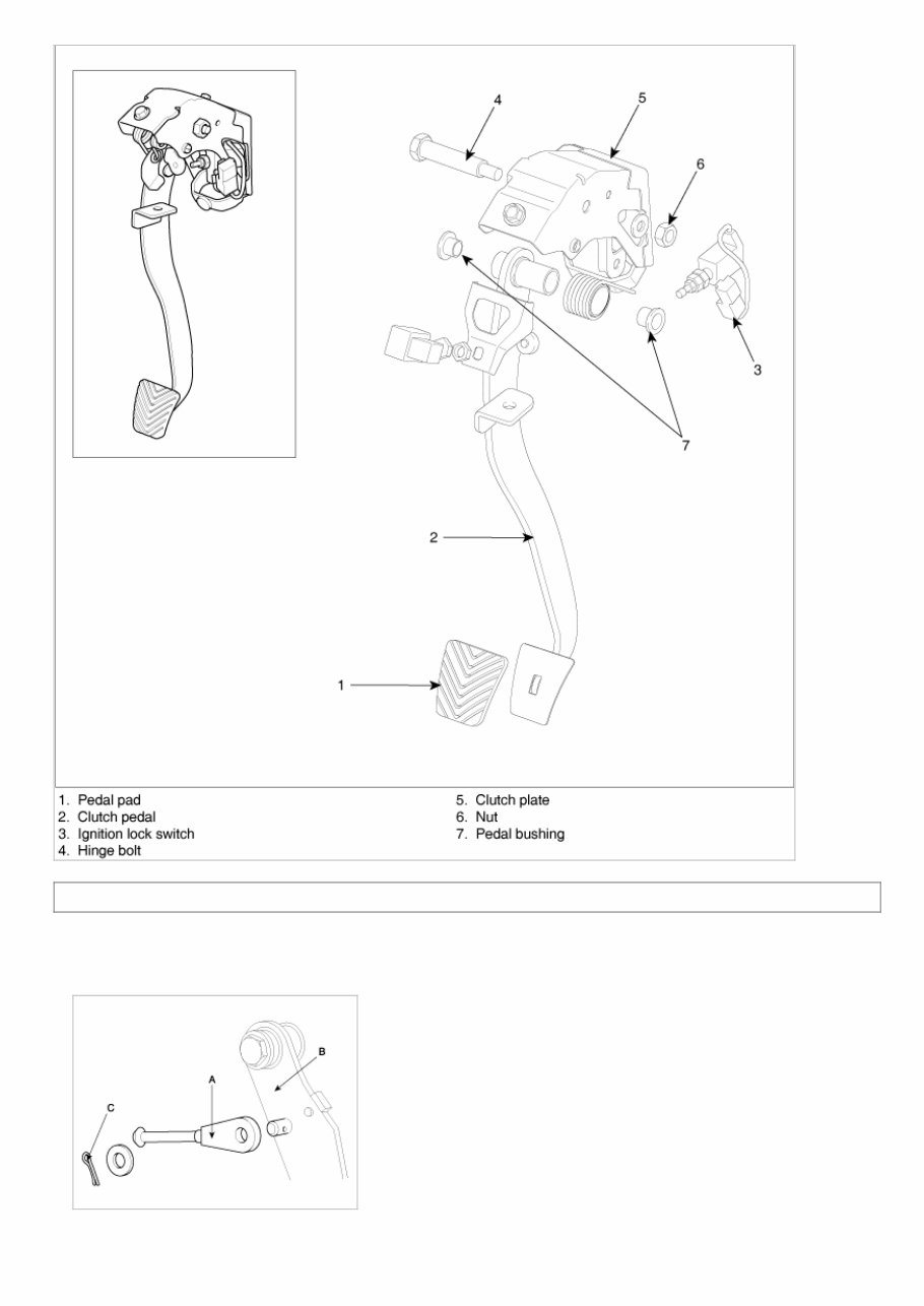
15/05/2012 https://www.kiatechinfo.com/viewer/toc_print.asp?vehicletype=Passenger&mfrcode=KM&area=KM… 9/12 https://www.kiatechinfo.com/viewer/toc_print.asp?vehicletype=Passenger&mfrcode=KM&area=KM… Clutch System > Clutch System > Clutch Master Cylinder > Repair procedures REMOVAL Do not spill brake fluid on the vehicle it may damage the paint, if brake fluid does contact the paint, wash it off immediately with water. 1. Remove the brake fluid from the clutch master cylinder reservoir with a syringe. 2. Clamp the clutch master cylinder hose(A). 3. Disconnect the hose from the cylinder by releasing the clutch master cylinder clamp. 4. Remove the clip(A) and disconnect the clutch tube(B). 5. Remove the pin and washer which connect the clutch pedal with the clutch master cylinder. 6. After loosening the clutch master cylinder assembly mounting bolts under the driver's seat, remove the clutch master cylinder. It can be helpful to do this step after removing the clutch pedal mounting bracket. INSTALLATION Installation is in the reverse order of removal. After installation, bleed the clutch hydaulic system. Clutch System > Clutch System > Clutch Pedal > Components and Components Location COMPONENTS
15/05/2012 https://www.kiatechinfo.com/viewer/toc_print.asp?vehicletype=Passenger&mfrcode=KM&area=KM… 10/12 https://www.kiatechinfo.com/viewer/toc_print.asp?vehicletype=Passenger&mfrcode=KM&area=KM… Clutch System > Clutch System > Clutch Pedal > Repair procedures REPLACEMENT 1. Disconnect the connector of the ignition lock switch. 2. Remove the split pin (C) connecting the mater cylinder's push rod (A) and the clutch pedal's arm (B).
This comprehensive Kia Magentis 2009 Service & Repair Manual contains professional service, maintenance, and troubleshooting information for all models, engines, trims, and transmission types of the 2009 Kia Magentis. It is an invaluable resource for both professional mechanics and DIY enthusiasts.
The manual includes detailed diagrams and specific repair information provided by the manufacturers. It covers general maintenance, troubleshooting, engine and transmission service/repair, brake system, wiring diagrams, electrical system, suspension, periodic lubrication, steering, cooling system, fuel injection/fuel system, emission system, heater/air conditioning, engine control system, chassis/body, restraint system, interior, differential/drive, axle, and much more.
Key features of this manual include:
Detailed substeps that expand on repair procedure information
Notes, cautions, and warnings throughout each chapter to pinpoint critical information
Numbered instructions to guide you through every repair procedure step by step
Bold figure numbers to quickly match illustrations with instructions
Detailed illustrations, drawings, and photos to guide you through every procedure
Enlarged insets to help you identify and examine parts in detail
Numbered table of contents for easy access to the required information
Troubleshooting and electrical service procedures combined with detailed wiring diagrams for ease of use
This manual is provided in a file format that allows for full printing and zooming in/out. It is compatible with all versions of Windows and Mac, and can be instantly accessed without any shipping costs or waiting time. The electronic format also allows for quick information searches, making it a convenient resource for all repair and maintenance needs.
With this professional quality and highly detailed Kia Magentis 2009 Service & Repair Manual, you will have the best resources available to work on your vehicle, saving both time and money on repair costs.