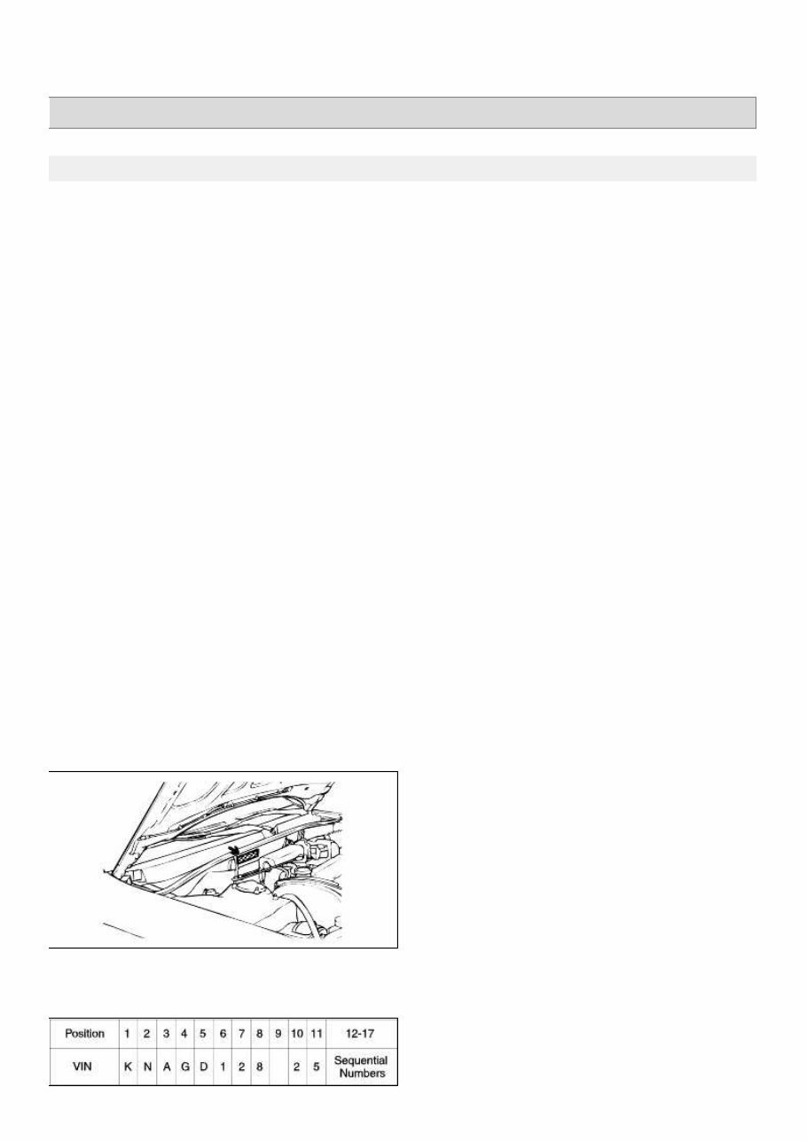
OPTIMA(MS) > 2005 > G 2.4 DOHC > General Information General Information > General Information > General Information GENERAL INFORMATION HOW TO USE THIS MANUAL This manual is divided into 21 sections. This first page of each section is marked with a black tab at the edge of the page. You can quickly find the first page of each section without looking through a full table of contents. Each section includes the essential removal, installation, adjustment and maintenance procedures for servicing all body styles. This information is current as of time of publication. An INDEX is provided on the first page of each section to guide you to the item to be replaced. TROUBLESHOOTING tables are included for each system to help you diagnose the system problem and find the cause. The repair for each possible cause is referenced in the remedy column to quickly lead you to the solution. DEFINITION OF TERMS Standard Value (Service standard) Indicates the value used as the standard for judging the quality of a part or assembly on inspection or the value to which the part or assembly is corrected and adjusted. It is given by a tolerance. Service Limit Shows the standard for judging the quality of a part or assembly on inspection and means the maximum or minimum value within which the part or assembly must be kept functionally or in strength. It is a value established outside the range ofstandard value WARNING , CAUTION, NOTE, ABBREVIATION • WARNING Information about an activity that could cause serious or severe personal injury or death to the driver, occupants or service technician. • CAUTION Information about an activity that could cause damage to the vehicle, or cause some personal injury. • NOTE A point of information. • ABBREVIATIONS DOHC : Double Over Head Camshaft V-6 : V-typed 6 Cylinder VEHICLE IDENTIFICATION NUMBER LOCATION The vehicle identification number (VIN) is on the top of the firewall and on the lower side of the left front door pillar. VEHICLE IDENTIFICATION NUMBER Vehicle identification number consists of 17 digit. Page 1 of 26 tomsn048@gmail.com
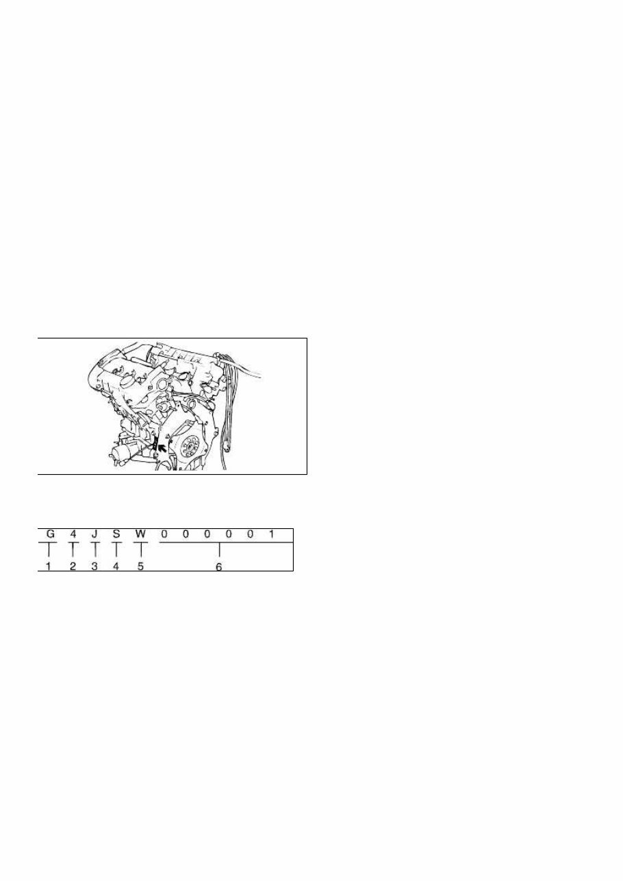
1 to 3 (Make / Vehicle Type): KNA - Kia Passenger Car 4 to 5 (Vehicle Line / Series): GD - OPTIMA 6 to 7 (Body Type): 12 - 4Door Seden 8 (Engine / Restraint): 6-Sirius II 2.4 8 - δ2.7 Gasoline & Air Bags (Manual Belts) 9 (Check Digit): To be calculated 10 (Model Year): 2 - 2002MY, 3 - 2003MY, 4 - 2004MY 11 (Plant): 5 - Hwasung Plant 12 to 17 (Sequential Numbers)) ENGINE IDENTIFICATION NUMBER LOCATION The engine identification number is stamped at the right front side on the top edge of the cylinder block. ENGINE IDENTIFICATION NUMBER Engine identification number consists of 11 digits. 1. Engine fuel G - Gasoline L - LPG D - Diesel 2. Engine range 4 - In line 4 cycle 4 cylinder 6 - V type 4 cycle 6 cylinder 3. Engine development order B - V6 Engine J - SIRIUS II DOHC Engine 4. Engine capacity N - 1836 cc P - 1997 cc, 1998 cc S - 2351 cc V - 2493 cc, 2497 cc 5. Product year 2 - 2002, 3 - 2003, 4 - 2004 Page 2 of 26
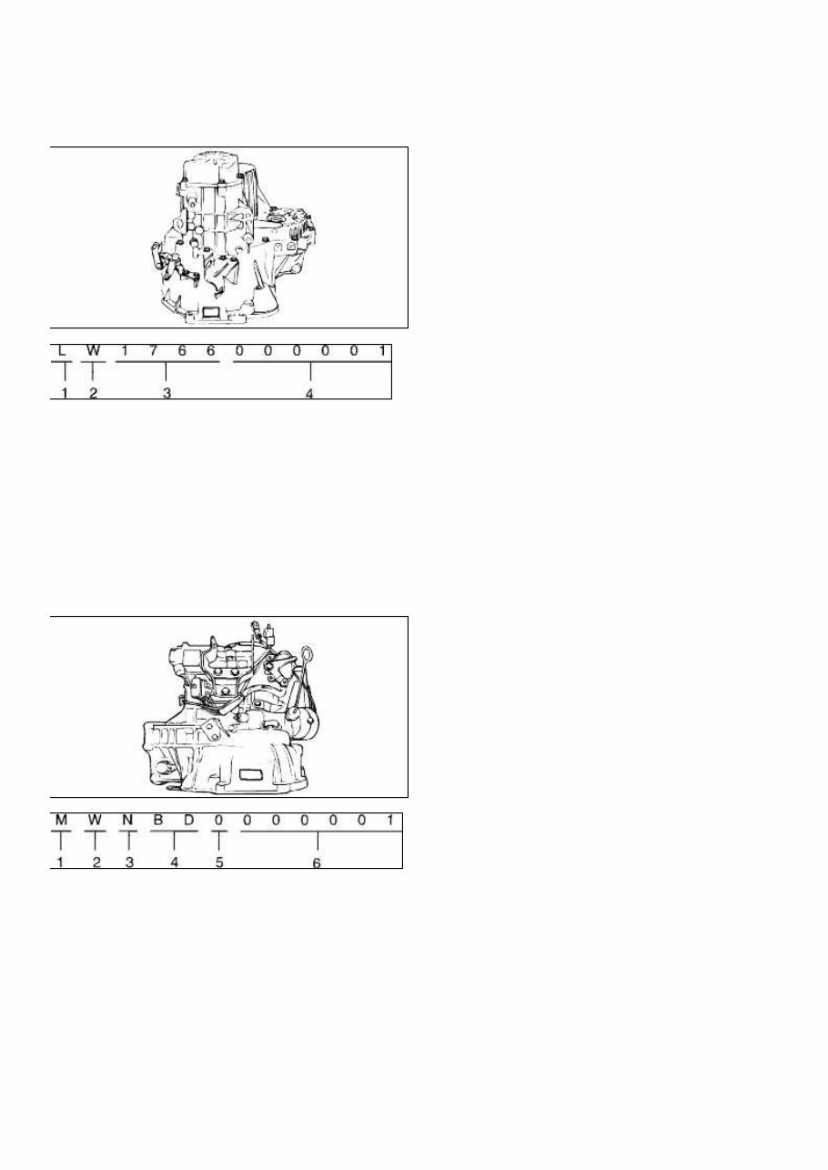
6. Engine production sequence number 000001 - 999999 TRANSAXLE IDENTIFICATION NUMBER LOCATION DESCRIPTION (MANUAL TRANSAXLE) 1. Model L : M5G Series 2. Product year 2 : 2002, 3 : 2003, 4 : 2004 3. Final gear ratio 1766 : 3,882 1665 : 4,063 4. Serial No. DESCRIPTION (AUTOMATIC TRANSAXLE) 1. Model C : KM 175-5 D : KM 175-6 H : F4A33 2. Product year 2 : 2002, 3 : 2003, 4 : 2004 3. Final gear ration F : 4.350 (KM 175-6) A : 3.958 (F4A33) 4. Classification of detail AD : 2.4 Liter Engine BD 2.0/ 2.5 Liter Engine 5. Spare 6. Serial No. PROTECTION OF THE VEHICLE Page 3 of 26 tomsn048@gmail.com
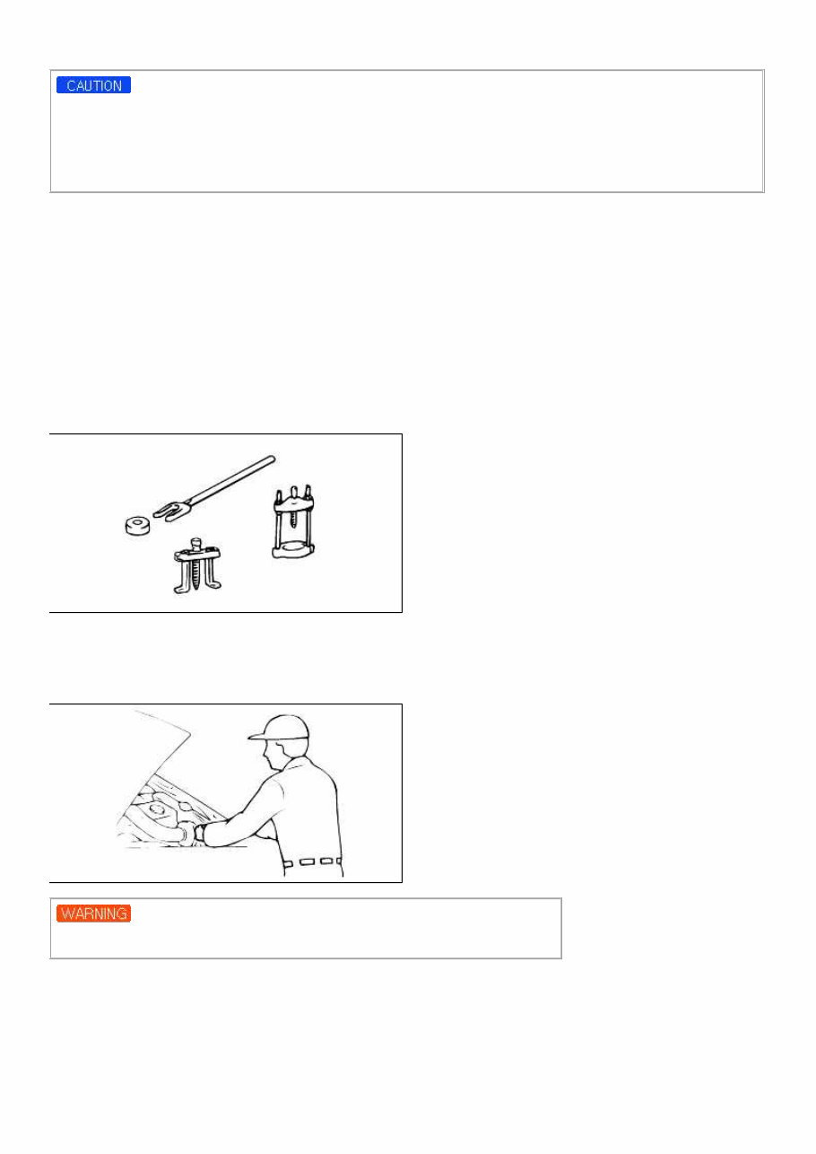
Always be sure to fenders, seats, and floor areas before starting work. The support rod must be inserted into the hole near the edge of the hood whenever you inspect the engine compartment to prevent the hood from falling and possibly injuring you. Assure that the support rod has been released prior to closing the hood. Always double check to be sure the hood is firmly latched before driving away. BASIC SAFETY WARNINGS WHEN WORKING ON THE VEHICLE The following precautions must be followed when jacking up the vehicle 1. Block wheels. 2. Use only specified jacking positions. 3. Support vehicle with safety stands (jack stands) 4. Never start the engine until you personally make certain the engine compartment is clear of tools and people. Never relyon another person to make the inspection-make the inspection yourself. PREPARATION OF TOOLS AND MEASURING EQUIPMENT Be sure that all necessary tools and measuring equipment are available before starting work activity. SPECIAL TOOLS Use special tools when they are required. REMOVAL OF PARTS First find the cause of trouble and then make sure whether removing or disassembling is required before starting the job. The failure to follow these instructions can lead to serious personal injury or death. DISASSEMBLY If the disassembly procedure is complex, requiring many parts to be disassembled, all parts should be disassembled in a way that will not affect their performance or external appearance. Page 4 of 26
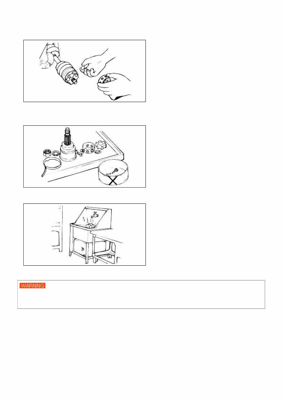
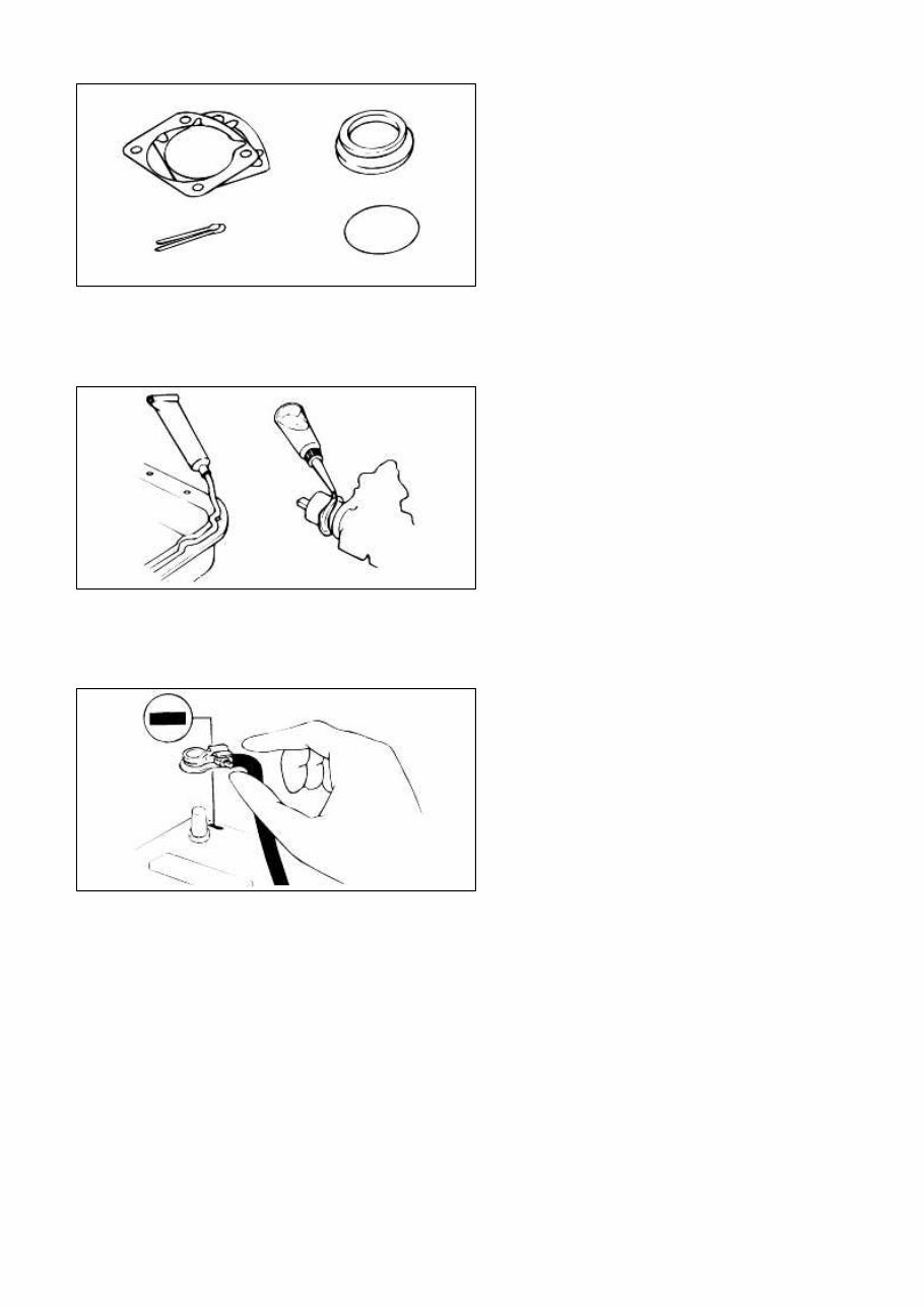
1. Inspection of parts Each part when removed should be carefully inspected for malfunction, deformation, damage, and other problems. 2. Arrangement of parts All disassembled parts should be carefully arranged for reassembly. Be sure to separate or otherwise identify the parts to be replaced from those that will be reused. 3. Cleaning parts for reuse All parts to be reused should be carefully and thoroughly clean-ed by the appropriate method. PARTS When replacing factory parts, use genuine parts. If using non-factory parts, you must ensure that such parts are the equivalent quality of genuine factory parts to avoid exposing customers to the risk of severe injury or death. REASSEMBLY Standard values, such as torques and certa in adjustments, must be strictly observed in the reassembly of all parts. If removed, these parts should be replaced with new ones. 1. Oil seals 2. Gaskets 3. 3. O-rings 4. Lock washers 5. Cotter pins (split pins) Page 5 of 26 tomsn048@gmail.com
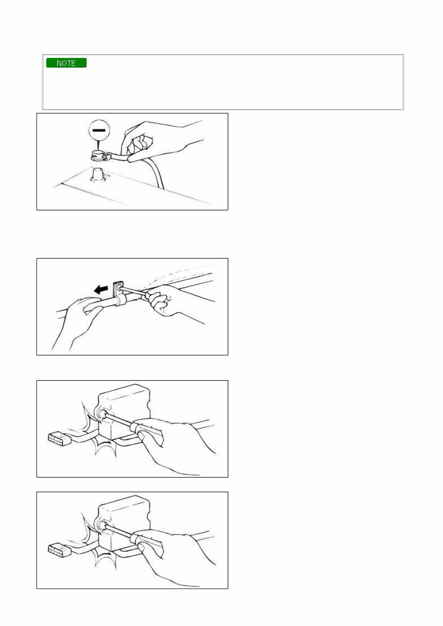
6. Plastic nuts Depending on where they are 1. Sealant should be applied to gaskets. 2. Oil should be applied to moving components of parts. 3. Specified oil or grease should be applied at the prescribed locations (oil seals, etc.) before assembly. ADJUSTMENT Use gauges and testers to correct adjustments to standard values. ELECTRICAL SYSTEM 1. Be sure to disconnect the battery cable from the negative (-) terminal of the battery. 2. Never pull on the wiring when disconnecting connectors. 3. Locking connectors will click when the connector is secure. 4. Handle sensors and relays carefully. Be careful not to drop them or hit them against other parts. RUBBER PARTS AND TUBING Always prevent gasoline or oil from touching rubber parts or tubing. Page 6 of 26
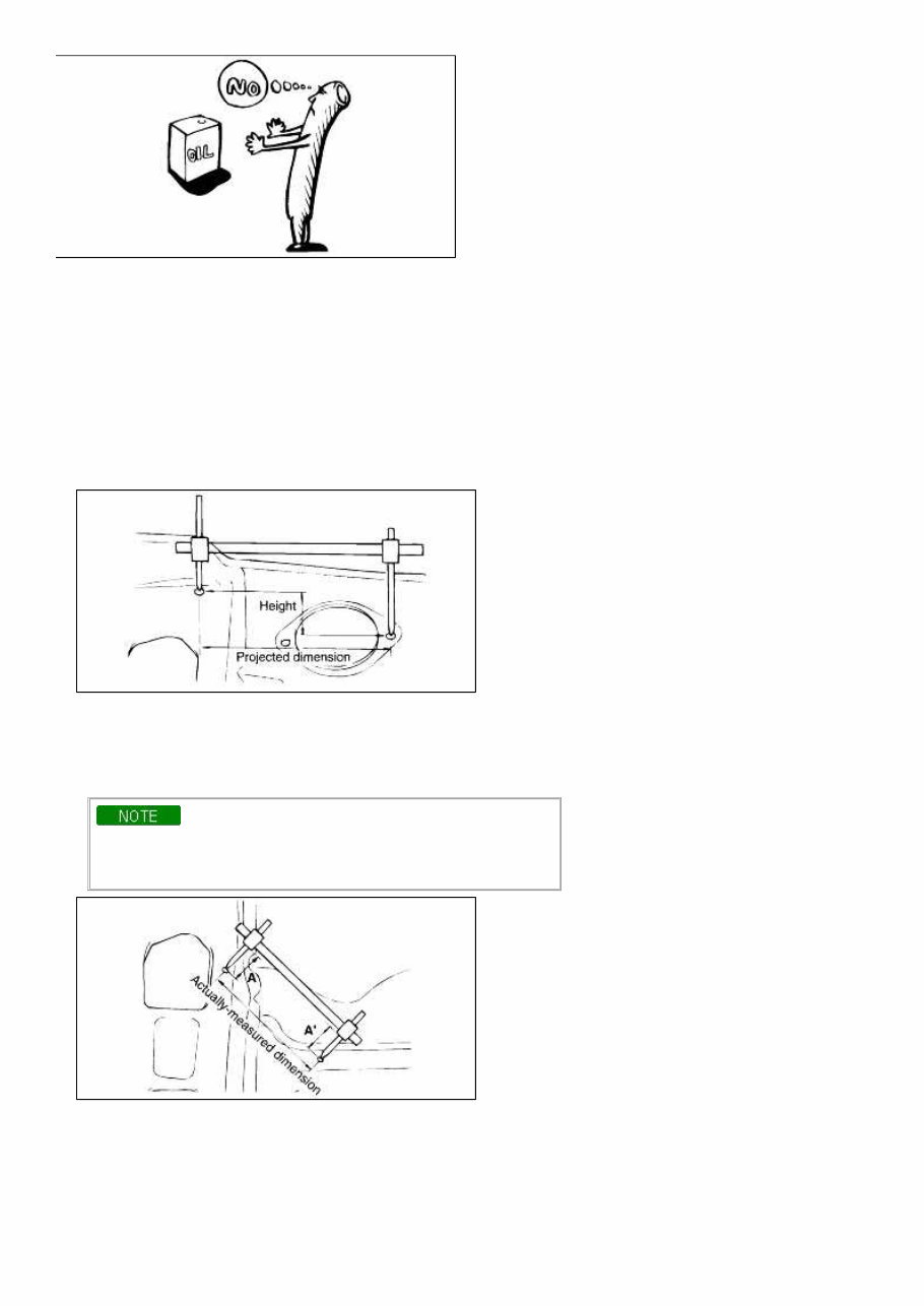
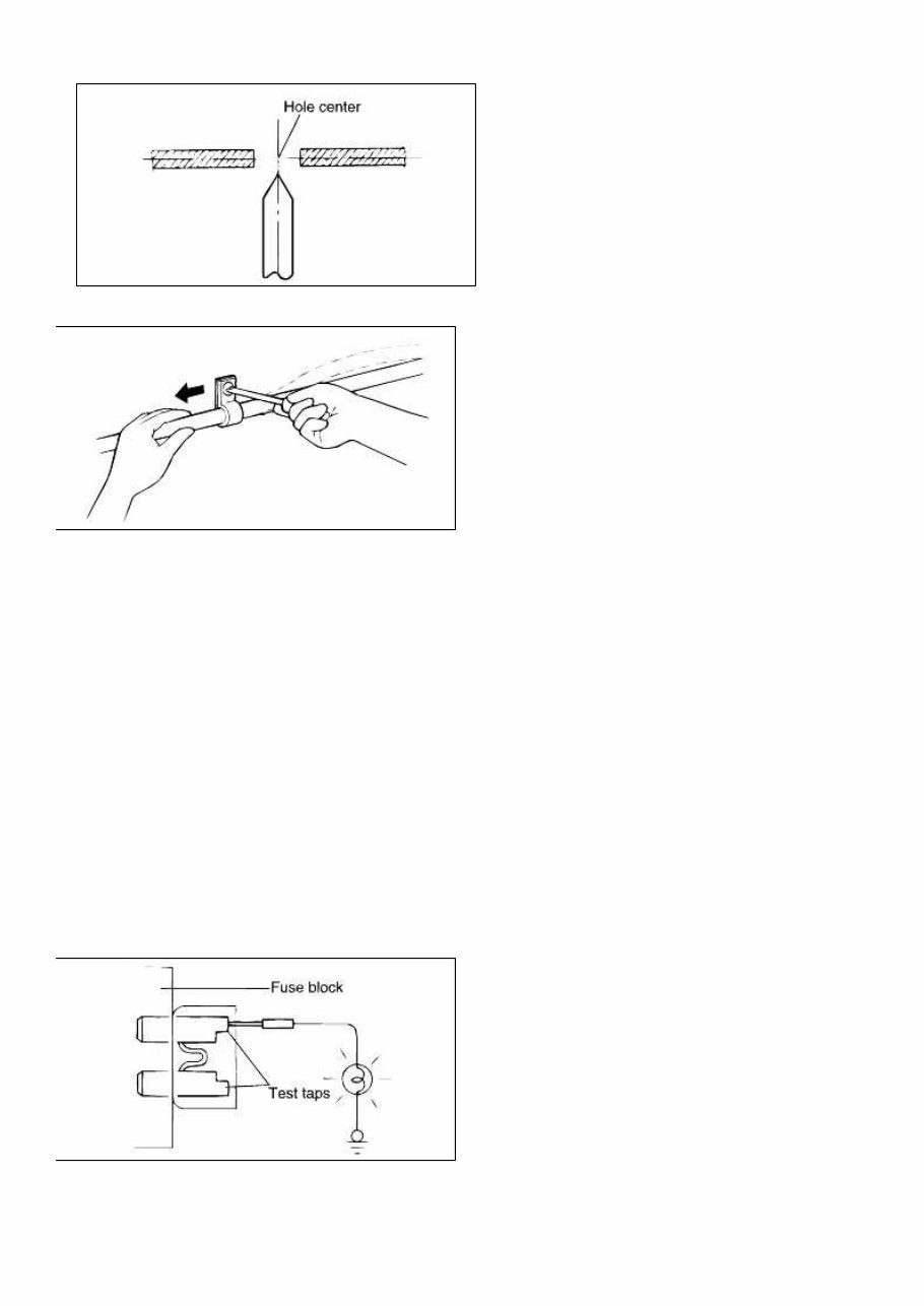
BODY DIMENSION MEASUREMENT 1. Basically, all measurements in this manual are taken with a tracking gauge. 2. When a measuring tape is used, check to be sure there is no elongation, twisting or bending. 3. For measuring dimensions, both projected dimension and actual-measurement dimension are used in this manual. PROJECTED DIMENSIONS 1. These are the dimensions measured when the measurement points are projected into the reference plane, and are the reference dimensions used for body alterations. 2. If the length of the tracking gauge probes are adjustable, make the measurement by lengthening one probe by the amount equivalent to the difference in height of the two surfaces. ACTUAL-MEASUREMENT DIMENSIONS 1. These dimensions indicate the actual linear distance between measurement points, and are the reference dimensions for use if a tracking gauge is used for measurement. 2. Measure by first adjusting both probes to the same length (A=A') Check the probes and gauge itself to make sure there is no free play. MEASUREMENT POINT Page 7 of 26 tomsn048@gmail.com
1. Measurements should be taken at the center of hole. CHECKING CABLES AND WIRES 1. Check the terminal for tightness. 2. Check terminals and wires for corrosion by battery electrolyte, etc. 3. Check terminals and wires for open circuit or potential open circuit. 4. Check wire insulation and coating for damage, cracks and degrading. 5. Check conductive parts of terminals for contact with other metallic parts (vehicle body and other parts). 6. Check grounding parts to verify that there is complete continuity between attaching bolt(s) and vehicle body. 7. Check for incorrect wiring. 8. Check that wires are clamped so as to prevent contact with sharp corners of the vehicle body, etc. or hot parts (exhaust manifold, pipe, etc.) 9. Check that wires are clamped firmly to secure enough clearance from the fan pulley, fan belt and other rotating or moving parts. 10. Check that the wires between the fixed parts such as the vehicle body and the vibrating parts such as the engine are made with adequate allowance for vehicle vibrations. CHECKING FUSES A blade type fuse has test taps provided to allow checking of the fuse itself without removing it from the fuse block. The fuse is okay if the test lamp comes on when its one lead is connected to the test taps (one at a time) and the other lead is grounded. (Change the ignition switch position adequately so that the fuse circuit becomes live.) SERVICING THE ELECTRICAL SYSTEM Page 8 of 26
1. Prior to servicing the electrical system, be sure to turn off the ignition switch and disconnect the battery ground cable. In the course of MFI or ELC system diagnosis, when the battery cable is removed, any diagnostic code retained by the computer will be cleared. Therefore, if necessary, read the diagnostic codes before removing the battery cable. 2. Secure the wiring harnesses by using clamps so that there is no slack. However, for any harness which passes to the engine or other vibrating parts of the vehicle, allow some slack within a range that does not allow the engine vibrations to ause the harness to come into contact with any of the surrounding parts, and then secure the harness by using a clamp. 3. If any section of a wiring harness interferes with the edge of a part, or a corner, wrap the section of the harness withtape or something similar in order to protect it from damage. 4. When installing any of the vehicle parts, be careful not to pinch or damage any of the wiring harnesses. Page 9 of 26 tomsn048@gmail.com
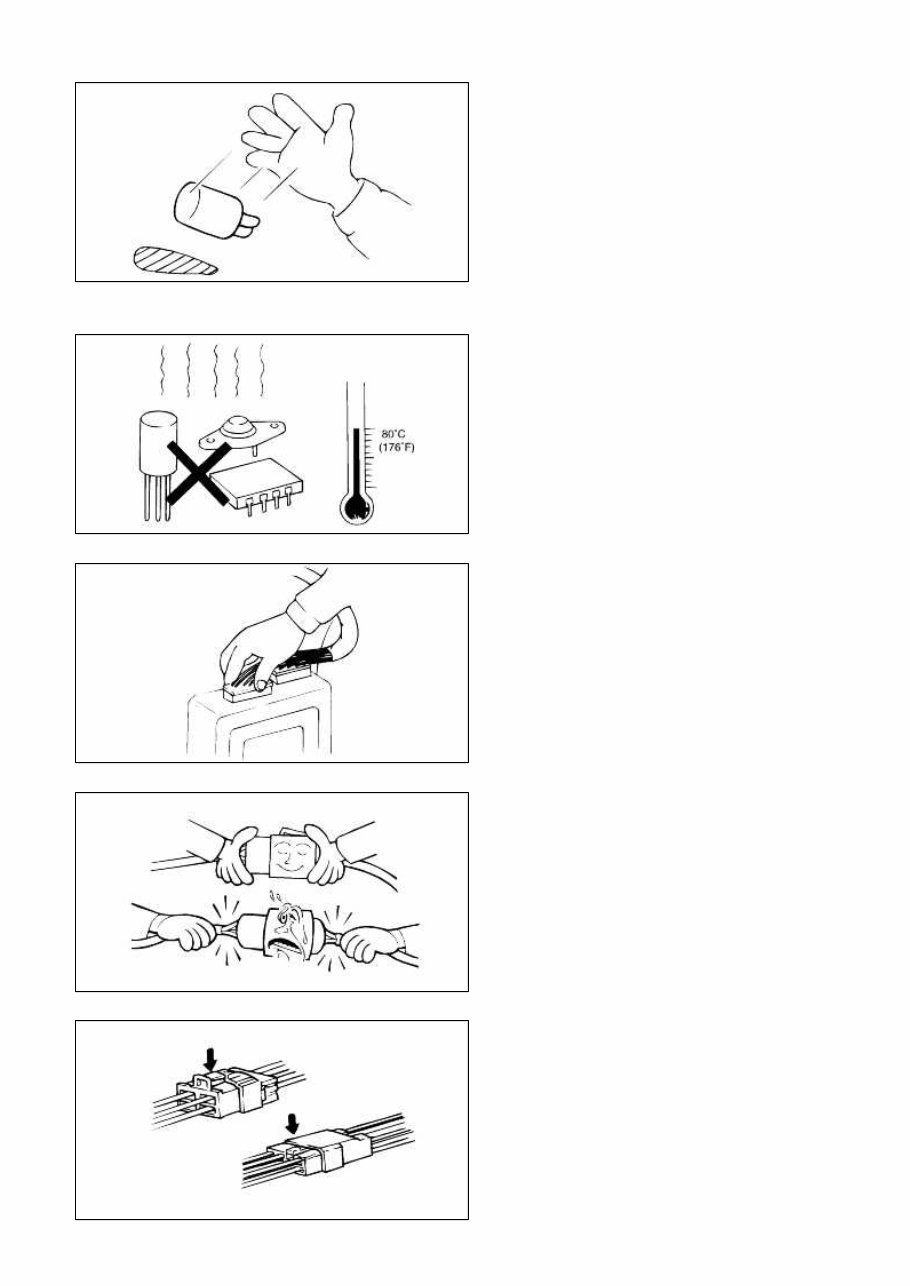
5. Never throw the relays, sensors and electrical parts, or expose them to strong shocks. 6. The electronic parts used in the computer, relays, etc. are easily damaged by heat. If there is a need for service operations that may cause the temperature to exceed 80°C (176°F), remove the electronic parts beforehand. 7. Loose connectors could troubles. Make sure that the connec-tors are connected securely. 8. When disconnecting a connector, be sure to pull only the connector, not the harness. 9. Disconnect connectors which have catches by pressing in the direction indicated by the arrows in the illustration. Page 10 of 26
This comprehensive Kia Magentis 2005 Workshop Repair Service Manual contains essential service, maintenance, and troubleshooting information for all models, engines, trims, and transmission types. It is a top-quality manual used by professional technicians in local service/repair shops and is equally beneficial for both professional mechanics and DIY enthusiasts.
Written by the manufacturers, this original workshop manual comprises hundreds of pages of diagrams and detailed information for specific vehicle or equipment repair. It includes detailed instructions, diagrams, and pictures for various repair procedures, making it easy to follow and perform repairs.
The manual covers general maintenance, troubleshooting, engine service/repair, transmission service/repair, brake system, wiring diagrams, electrical system, suspension, periodic lubrication, steering, cooling system, fuel injection/fuel system, emission system, heater/air conditioning, engine control system, chassis/body, restraint system, interior, differential/drive, axle, and much more.
Key features of this manual include detailed substeps, notes, cautions, warnings, numbered instructions, bold figure numbers, detailed illustrations, enlarged insets, and a numbered table of contents for easy navigation. It also facilitates diagnosing and repairing electrical system problems with detailed wiring diagrams.
This manual is available in a digital format, allowing for easy access and printing of specific sections for use during repairs or services. It is compatible with all versions of Windows and Mac, and can be instantly accessed without any shipping costs or waiting time.
With this professional quality and highly detailed Kia Magentis 2005 Service Repair Workshop Manual, you will have the best resources available to work on your vehicle, saving both time and money on repair costs.
Product Details:
File Format: .PDF (Portable Document Format)
Language: English
Specifications: Full Printable
Zoom IN/OUT: Yes
Delivery: Instant
Requirements: Adobe Reader & WinZip
Get your hands on this comprehensive manual to ensure your Kia Magentis 2005 remains in top condition and to handle any maintenance or repairs with confidence.