2004 > Alpha 1.6L DOHC > Fundamental procedures NOTICES, CAUTIONS AND WARNINGS As you read through the various procedures, you will encounter Notices, Cautions and Warnings. Each one is there for a specific purpose. Notices give you added information that will assist you in completing a particular procedure.Cautions prevent you from making an error that could damage the vehicle.Warnings remind you to be especially careful in specific areas where carelessness can cause personal injury. The following items contain general procedures you should always follow when working on a vehicle: PROTECTION OF VEHICLE Always cover fenders, seats, and floor areas before starting work. Operate the engine only in a well-ventilated area to avoid carbon monoxide poisoning. A WORD ABOUT SAFETY The following precautions must be followed when jacking up the vehicle: 1. Block the wheels. 2. Use only the specified jacking positions. 3. Support the vehicle with safety stands. The engine compartment must be clear of tools and people before starting the engine. PREPARATION OF TOOLS AND MEASURING EQUIPMENT All necessary tools and measuring equipment should be available before starting any work. SPECIAL SERVICE TOOLS (SST'S) Use special service tools when they are required. SST's can be found under"preparation"prior to any procedure requiring them.
REMOVAL OF PARTS Begin work only after first learning which parts and subassemblies must be removed and disassembled for replacement or repair. DISASSEMBLY If the disassembly procedure is complex, requiring many parts to be disassembled, all parts should be disassembled in a way that will not affect their performance or external appearance. Additionally, these parts should be identified so that reassembly can be done easily and efficiently. INSPECTION OF PARTS When removed, each part should be carefully inspected for malfunction, deformations, damage, or other problems. Arrangement of parts All disassembled parts should be carefully arranged for reassembly. Separate or otherwise identify the parts to be replaced from those that will be reused. CLEANING PARTS FOR REUSE
All parts that will be reused should be carefully and thoroughly cleaned using appropriate methods. REASSEMBLY Standard values, such as torques and certain adjustments, must be strictly observed in the reassembly of all parts. If removed, the following parts should be replaced with new ones: 1. Oil seals 2. O-rings 3. Cotter pins 4. Gaskets 5. Lock washers 6. Nylon nuts DEPENDING ON LOCATION: 1. Sealant should be applied or new gaskets installed. 2. Oil should be applied to the moving components of parts. 3. Specified oil or grease should be applied at the appropriate locations (such as oil seals) before reassembly. Adjustments Use appropriate gauges and/or testers when making adjustments. Rubber parts and tubing Prevent gasoline or oil from contacting rubber parts or tubing.
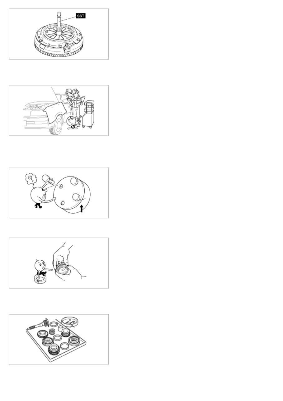
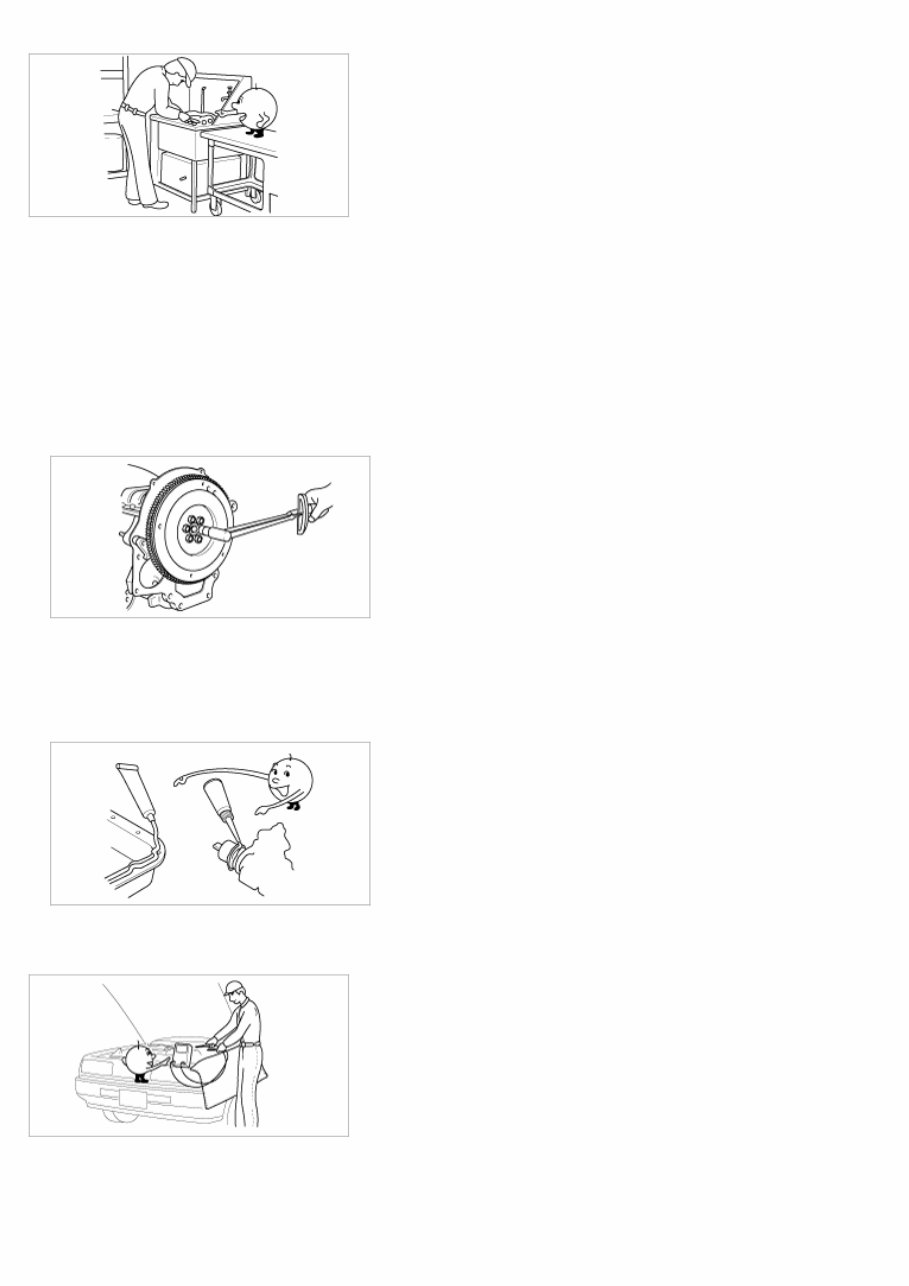
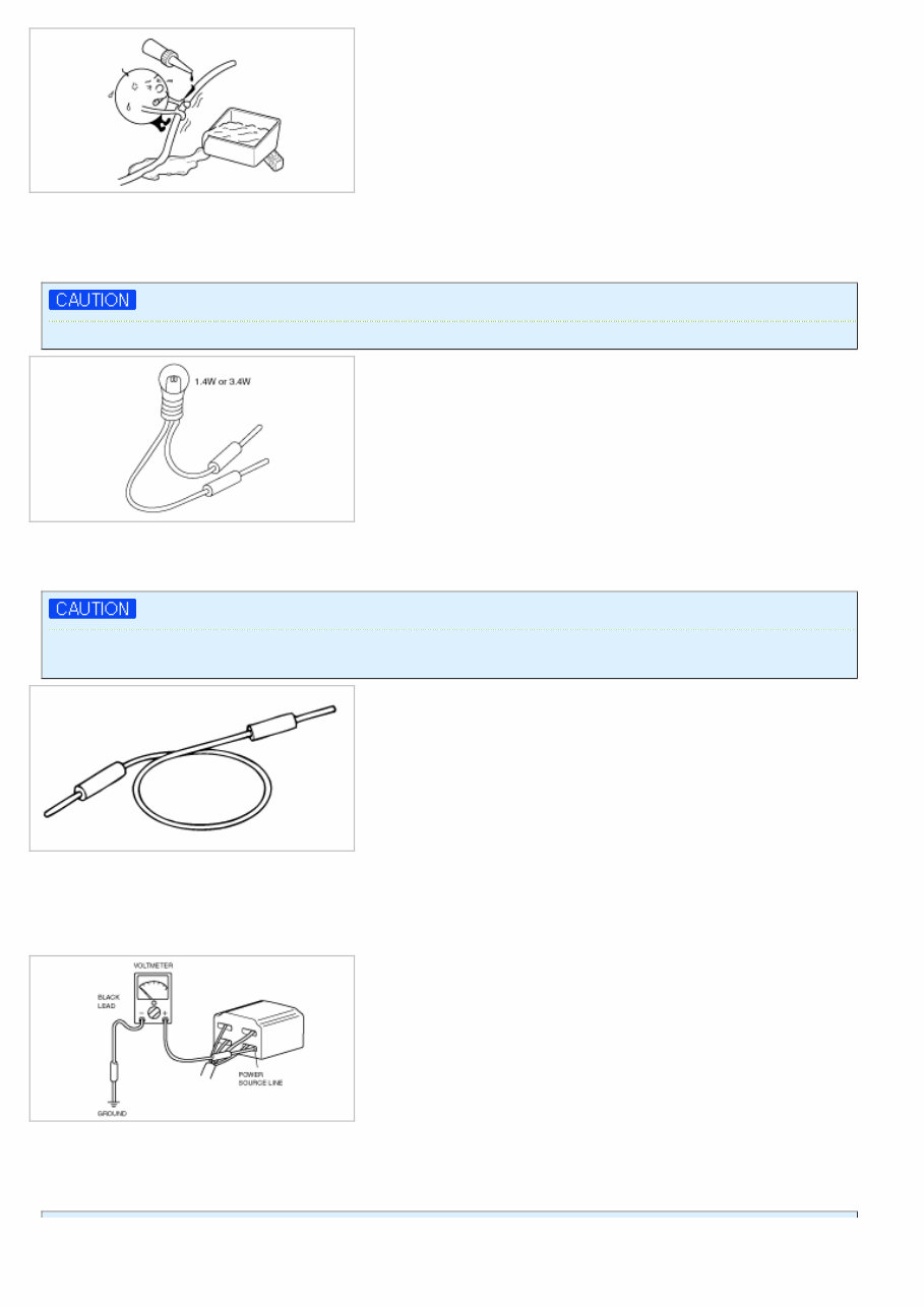
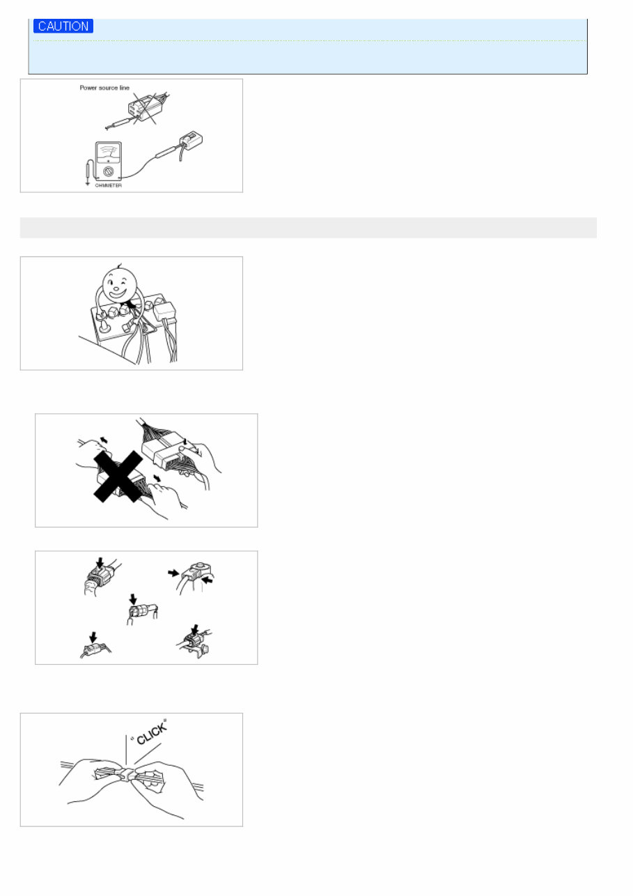
Electrical troubleshooting tools (Test Light) The test light, as shown in figure, uses a 12V bulb. The two lead wires should be connected to probes. The test light is used for simple voltage checks and in checking for short circuits. When checking the engine control module (ECM), never use a bulb exceeding 3.4W. Electrical troubleshooting tools(Jumper wire) The jumper wire is used for testing by shorting across switch terminals ground connections. Do not connect a jumper wire from the power source line to a body ground. Such a connection may cause damage to harnesses or electronic components. VOLTMETER The DC voltmeter measures circuit voltage. A voltmeter with a range of 15V or more is used by connecting the positive (+) probe (red lead wire) to the point where voltage is be measured, and the negative (-) probe (black lead wire)to a bodyground. OHMMETER The ohmmeter is used to measure the resistance between two points in circuit and also to check for continuity and the diagnosis of short circuits.
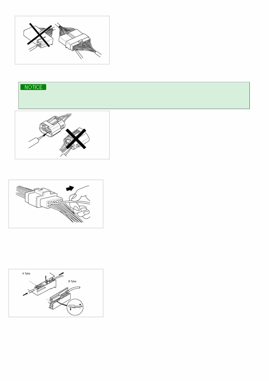
Do not attempt to connect the ohmmeter to any circuit in which voltage is applied. Such a connection may damage the ohmmeter. Electrical parts Battery cable Before disconnecting connectors or replacing electrical parts, disconnect the negative battery cable. Connectors(Removal of connector) 1. Never pull on the wiring harness when disconnecting connectors. 2. Connectors can be removed by pressing or pulling lock lever. Connectors(Locking a connector) Listen for a click when locking connectors. This sound indicates that they are securely locked. Connectors(Inspection)
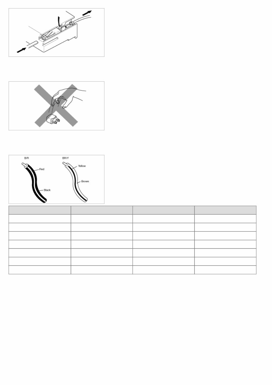
1. When a tester is used to check for continuity or to measure voltage, insert tester probe from wire harness side. 2. Check terminals of waterproof connectors from connector side because they cannot be accessed from harness side. a. Use a fine wire to prevent damage to the terminal. b. Do not damage the terminal when inserting the tester lead. Terminals(Inspection) Pull lightly on individual wires to ensure that they are secured in the terminal. REPLACEMENT OF TERMINALS Use appropriate tools to remove terminal as shown. When installing the terminal, insert it until it locks securely. FEMALE Insert a thin piece of metal from the terminal side of the connector, and then, with the terminal locking tab pressed down, pull the terminal out of the connector. MALE Follow the same procedure as female-type terminal.
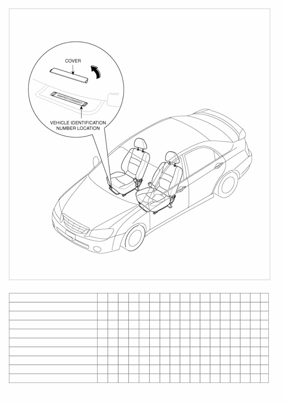
SENSORS, SWITCHES, AND RELAYS Always handle sensors, switches and relays carefully. Do not drop them or accidentally strike them against other parts. WIRING COLOR CODES Two-color wires are indicated by a two-color code symbol. The firstcolor indicates the base color of the wire; the second color indicates the color of the stripe. CODE COLOR CODE COLOR B BLACK P PINK BR BROWN R RED G GREEN S SILVER(LIGHT BLUE) GY GRAY T TAWNY L BLUE V VIOLET LG LIGHT GREEN W WHITE O ORANGE Y YELLOW VEHICLE IDENTIFICATION NUMBER LOCATION
VEHICLE IDENTIFICATION NUMBER DESCRIPTION EXCEPT EUROPE VEHICLE 1 2 3 4 5 6 7 8 9 10 11 12 13 14 15 16 17 4 N/B 1.6 GASOLINE M/T K N A F E 2 2 2 2 4 5 0 0 0 0 0 1 4 N/B 1.6 GASOLINE A/T K N A F E 2 2 2 3 4 5 0 0 0 0 0 1 4 N/B 2.0 GASOLINE M/T K N A F E 2 2 3 2 4 5 0 0 0 0 0 1 4 N/B 2.0 GASOLINE A/T K N A F E 2 2 3 3 4 5 0 0 0 0 0 1 5 H/B 1.6 GASOLINE M/T K N A F E 2 4 2 2 4 5 0 0 0 0 0 1 5 H/B 1.6 GASOLINE A/T K N A F E 2 4 2 3 4 5 0 0 0 0 0 1 5 H/B 2.0 GASOLINE M/T K N A F E 2 4 3 2 4 5 0 0 0 0 0 1 5 H/B 2.0 GASOLINE A/T K N A F E 2 4 3 3 4 5 0 0 0 0 0 1 5 H/B 2.0 DIESEL M/T K N A F E 2 4 4 2 4 5 0 0 0 0 0 1
1 - 3 : Make / Vehicle type - KNA = Kia Passenger Car 4 - 5 : Vehicle Line / Series - FE = LD (SPECTRA) 6 - 7 : Body type - 22 = 4Door Notchback (Sedan) - 24 = 5Door Hatchback 8 : Engine type - 2 = 1.6 Gasoline - 3 = 2.0 Gasoline - 4 = 2.0 Diesel 9 : Transmission type or Check digit - 2 = 5 speed manual - 3 = Automatic - To be calculated 10 : Model year - 4 = 2004, 5 = 2005 11 : Plant location - 5 = Hwasung plant 12 - 17 : Sequential number - 000001 ~ 999999 VEHICLE IDENTIFICATION NUMBER DESCRIPTION FOR EUROPE VEHICLE 0 1 2 3 4 5 6 7 8 9 10 11 12 13 14 15 16 17 0 4 N/B 1.6 GASOLINE M/T - K N E F E 2 2 2 2 4 5 0 0 0 0 0 1 - 4 N/B 1.6 GASOLINE A/T - K N E F E 2 2 2 3 4 5 0 0 0 0 0 1 - 4 N/B 2.0 GASOLINE M/T - K N E F E 2 2 3 2 4 5 0 0 0 0 0 1 - 4 N/B 2.0 GASOLINE A/T - K N E F E 2 2 3 3 4 5 0 0 0 0 0 1 - 4 N/B 2.0 DIESEL M/T - K N E F E 2 2 4 2 4 5 0 0 0 0 0 1 - 5 H/B 1.6 GASOLINE M/T - K N E F E 2 4 2 2 4 5 0 0 0 0 0 1 - 5 H/B 1.6 GASOLINE A/T - K N E F E 2 4 2 3 4 5 0 0 0 0 0 1 - 5 H/B 2.0 GASOLINE M/T - K N E F E 2 4 3 2 4 5 0 0 0 0 0 1 - 5 H/B 2.0 GASOLINE A/T - K N E F E 2 4 3 3 4 5 0 0 0 0 0 1 - 5 H/B 2.0 DIESEL M/T - K N E F E 2 4 4 2 4 5 0 0 0 0 0 1 - 1 - 3 : Make / Vehicle type - KNE = Kia Passenger Car 4 - 5 : Vehicle Line / Series - FE = LD (SPECTRA) 6 - 7 : Body type - 22 = 4Door Notchback (Sedan) - 24 = 5Door Hatchback 8 : Engine type - 2 = 1.6 Gasoline - 3 = 2.0 Gasoline - 4 = 2.0 Diesel 9 : Transmission type - 2 = 5 speed manual - 3 = Automatic 10 : Model year - 4 = 2004, 5 = 2005 11 : Plant location - 5 = Hwasung plant
Fixing problems on your vehicle is a Do-It-Yourself approach with this repair manual as it contains every troubleshooting and replacement procedure provided by the manufacturer, including step-by-step instructions, clear images, and exploded-view illustrations.
The durability of your vehicle is unquestionable, but you also know that no matter how tough it is, regular maintenance is definitely required. And even when properly maintained, with time, some parts will eventually wear out and will need to be replaced.
Luckily, that's where a good repair manual will come in handy, providing you with the manufacturer's recommended troubleshooting charts and replacement procedures; basically, everything you need to fix your vehicle. As a result, you’ll be able to save on repairs, increase your vehicle’s reliability, and keep the repair shop at bay — what’s not to like, right?
The manual contains every troubleshooting and replacement procedure provided by the manufacturer, including step-by-step instructions, exploded-view illustrations, and clear images.
No need to flip through hundreds of pages to find specific information; no more greasy, torn, or lost pages anymore! Carry them around, search them, screenshot them, bookmark them — much better than a traditional bound manual if you ask me.
Of course, if you prefer to have a physical copy, nothing prevents you from printing it out too.
Format: .pdf Printable: Yes Language: English Compatibility: Pretty much any electronic device, incl. PC & Mac computers, Android and Apple smartphones & tablet, etc. Requirements: Adobe Reader (free)