2009-10 BRAKES ABS (Anti-Lock Brake System) - Borrego + 2010 Canadian COMPONENTS AND COMPONENT LOCATIONS COMPONENTS 2009 Kia Borrego LX 2009-10 BRAKES ABS (Anti-Lock Brake System) - Borrego + 2010 Canadian
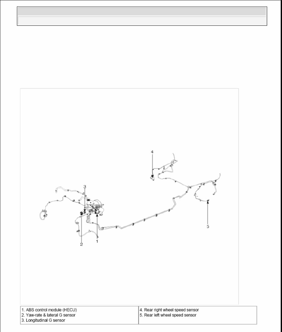
Fig. 1: Locating Brake System Components Courtesy of KIA MOTORS AMERICA, INC. DESCRIPTION AND OPERATION DESCRIPTION This specification applies to HCU (Hydraulic Control Unit) and ECU (Electronic Control Unit) of the HECU. (Hydraulic and Electronic Control Unit) This specification is for the wiring design and installation of ABS/ESC ECU. This unit has the functions as follows. Input of signal from Pressure sensor, Steering angle sensor, Yaw & Lateral G sensor, the wheel speed sensors attached to each wheel. Control of braking force/traction force/yaw moment. Failsafe function. Self diagnosis function. Interface with the external diagnosis tester. Installation position : engine compartment Brake tube length from Master cylinder port to HECU inlet port should be max. 1m The position should not be close to the engine block and not lower than the wheel. Operation The ECU shall be put into operation by switching on the operating voltage (IGN). On completion of the initialization phase, the ECU shall be ready for operation. In the operating condition, the ECU shall be ready, within the specified limits (voltage and temperature), to process the signals offered by the various sensors and switches in accordance with the control algorithm defined by the software and to control the hydraulic and electrical actuators. Wheel Sensor Signal Processing The ECU shall receive wheel speed signal from the four active wheel sensors. The wheel signals are converted to voltage signal by the signal conditioning circuit after receiving current signal from active wheel sensors and given as input to the MCU. Solenoid Valve Control When one side of the valve coil is connected to the positive voltage that is provided through the valve relay and 2009 Kia Borrego LX 2009-10 BRAKES ABS (Anti-Lock Brake System) - Borrego + 2010 Canadian
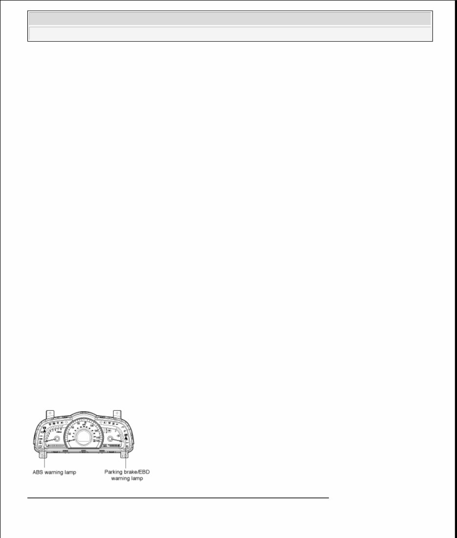
the other side is connected to the ground by the semiconductor circuit, the solenoid valve goes into operation. The electrical function of the coils are always monitored by the valve test pulse under normal operation conditions. Voltage Limits Overvoltage When overvoltage is detected (above 17 ± 0.5 V), the ECU switches off the valve relay and shuts down the system. When voltage is returned to operating range, the system goes back to the normal condition after the initialization phase. Undervoltage In the event of undervoltage (below 10V), ABS control shall be inhibited and the warning lamp shall be turned on. When voltage is returned to operating range, the warning lamp is switched off and ECU returns to normal operating mode. Pump Motor Checking The ECU performs a pump motor test at a speed of 15 km/h (9 MPH) once after IGN is switched on. Diagnostic Interface Failures detected by the ECU are encoded on the ECU, stored in a EEPROM and read out by diagnostic equipment when the ignition switch is turned on. The diagnosis interface can also be used for testing the ECU during production of the ECU and for actuating the HCU in the test line of manufacturer (Air-bleeding line or Roll and Brake Test line). Warning Lamp Module Fig. 2: Identifying ABS Warning Lamp & Parking Brake/EBD Warning Lamp Courtesy of KIA MOTORS AMERICA, INC. 1. ABS Warning Lamp module 2009 Kia Borrego LX 2009-10 BRAKES ABS (Anti-Lock Brake System) - Borrego + 2010 Canadian
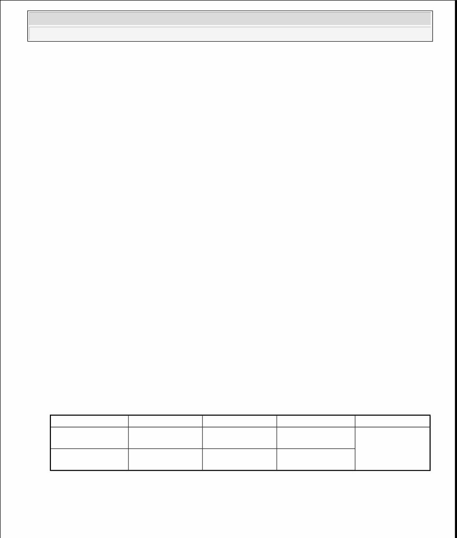
The active ABS warning lamp module indicates the self-test and failure status of the ABS. The ABS warning lamp shall be on: A. During the initialization phase after IGN ON. (continuously 3 seconds). B. In the event of inhibition of ABS functions by failure. C. During diagnostic mode. D. When the ECU Connector is separated from ECU. 2. PARKING/EBD warning lamp module The active EBD warning lamp module indicates the self-test and failure status of the EBD. However, in case the Parking Brake Switch is turned on, the EBD warning lamp is always turned on regardless of EBD functions. The EBD warning lamp shall be on: A. During the initialization phase after IGN ON. (continuously 3 seconds). B. When the Parking Brake Switch is ON or brake fluid level is low. C. When the EBD function is out of order. D. During diagnostic mode. E. When the ECU Connector is separated from ECU. ABS Control 1. NORMAL BRAKING without ABS Under the normal braking, voltage is not supplied to solenoid valve, inlet valve is opened and outlet valve is closed. When the brake is depressed, brake fluid is supplied to the wheel cylinder via solenoid valve to activate the brake. When the brake is released, brake fluid goes back to the master cylinder via inlet valve and check valve. ABS CONTROL - NORMAL BRAKING WITHOUT ABS Solenoid valve State Valve Passage Pump motor Inlet valve (NO) OFF Open Master cylinder <=> Wheel cylinder OFF Outlet valve (NC) OFF Close Wheel cylinder <=> Reservoir 2009 Kia Borrego LX 2009-10 BRAKES ABS (Anti-Lock Brake System) - Borrego + 2010 Canadian
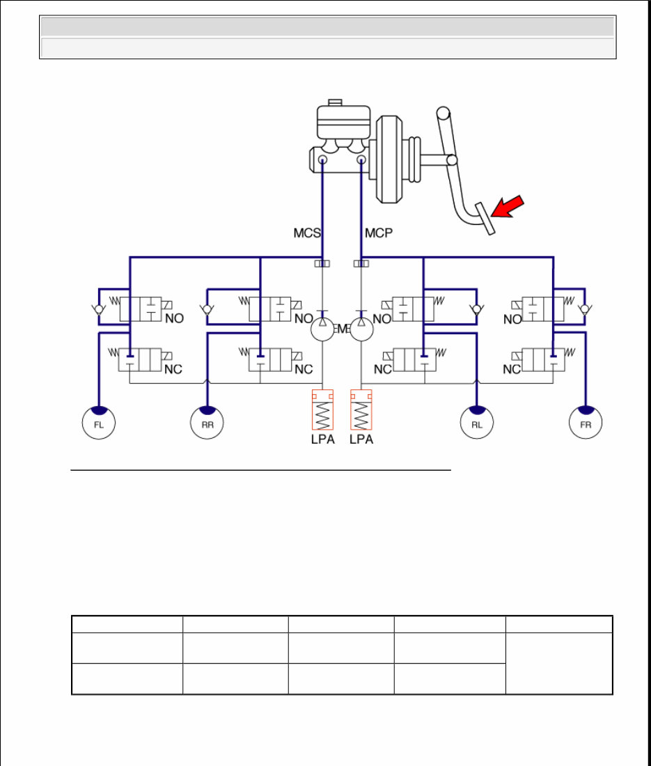
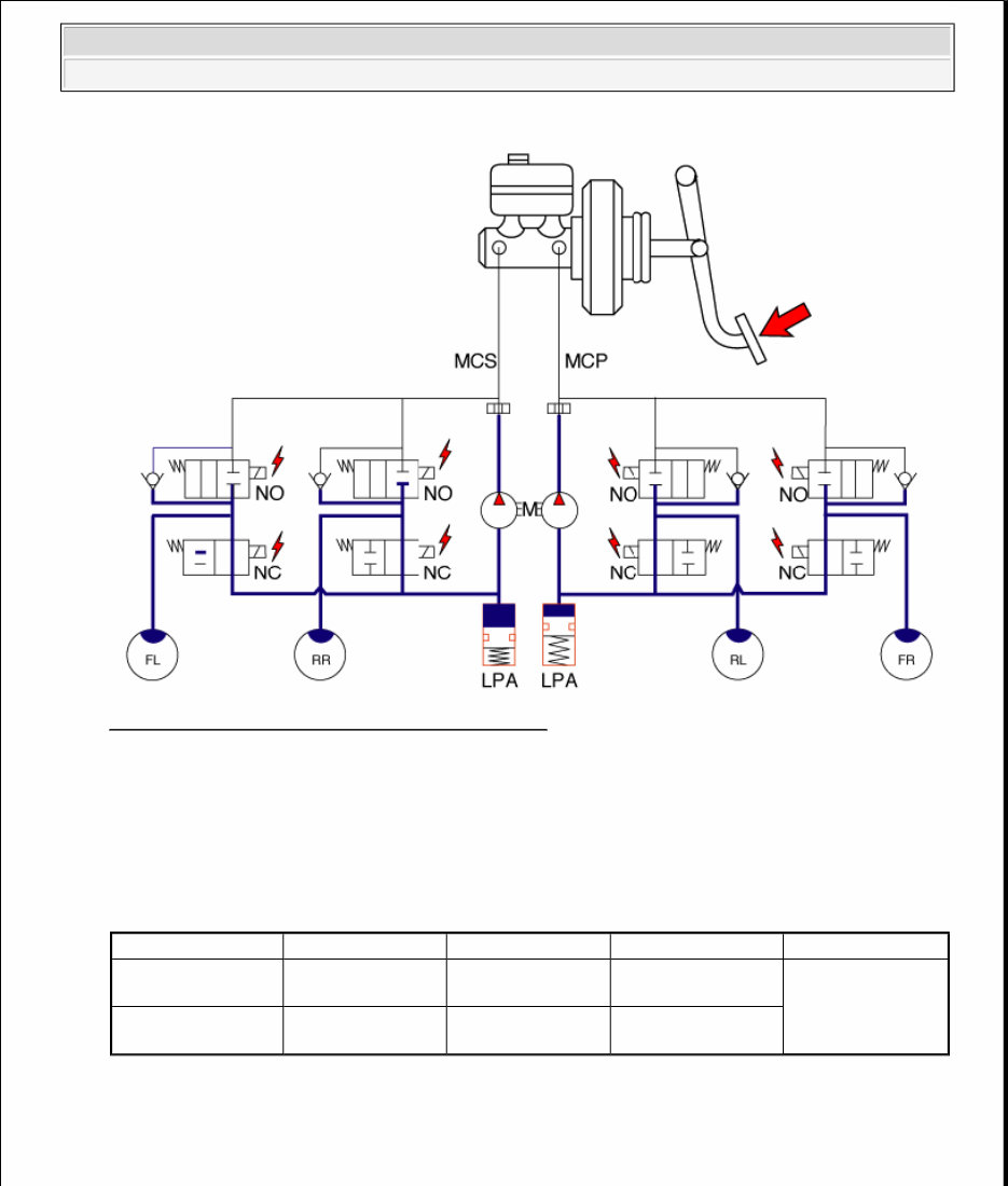
Fig. 3: ABS Control System Diagram (Normal Braking Without ABS) Courtesy of KIA MOTORS AMERICA, INC. 2. Dump Mode Under the emergency braking, if the wheels start to lock up, HECU sends a signal to the solenoid valve to decrease the brake fluid, then voltage is supplied to each solenoid. At this time inlet valve is closed and brake fluid is blocked from the master cylinder. Conversely outlet valve is opened and brake fluid passes through wheel cylinder to reservoir, resulting in pressure decrease. ABS CONTROL - DUMP MODE Solenoid State Valve Passage Pump motor Inlet valve (NO) ON Close Master cylinder <=> Wheel cylinder ON Outlet valve (NC) ON Open Wheel cylinder <=> Reservoir 2009 Kia Borrego LX 2009-10 BRAKES ABS (Anti-Lock Brake System) - Borrego + 2010 Canadian
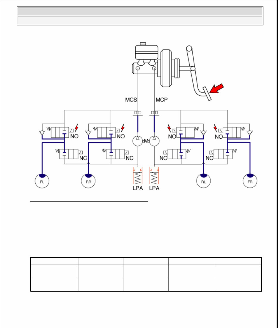
Fig. 4: ABS Control System Diagram (Dump Mode) Courtesy of KIA MOTORS AMERICA, INC. 3. Hold Mode When the brake fluid pressure is maximally decreased in wheel cylinder, HECU sends a signal to solenoid valve to keep the fluid pressure, voltage is supplied to inlet valve but it is not supplied to outlet valve. At this time inlet and outlet valves are closed and brake fluid is kept in wheel cylinder. ABS CONTROL - HOLD MODE Solenoid State Valve Passage Pump motor Inlet valve (NO) ON Close Master cylinder <=> Wheel cylinder OFF Outlet valve (NC) OFF Close Wheel cylinder <=> Reservoir 2009 Kia Borrego LX 2009-10 BRAKES ABS (Anti-Lock Brake System) - Borrego + 2010 Canadian
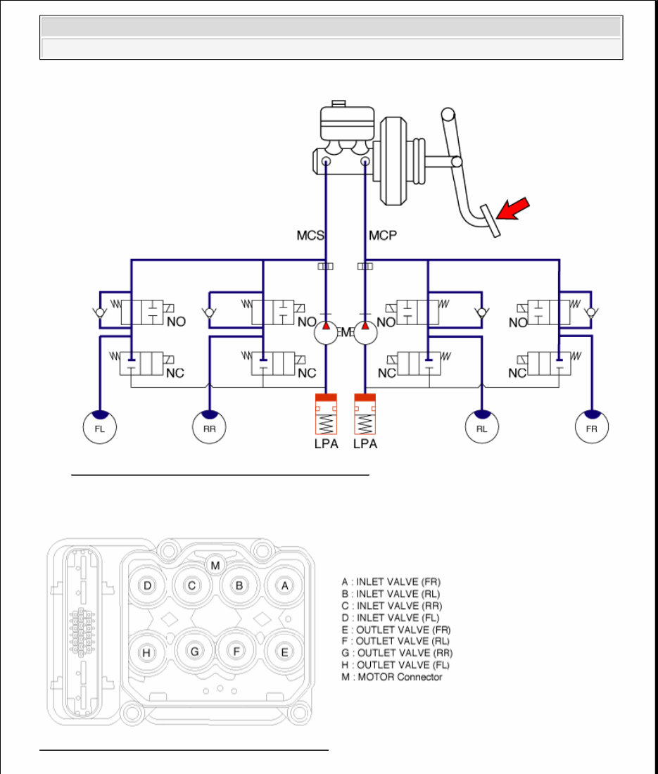
Fig. 5: ABS Control System Diagram (Hold Mode) Courtesy of KIA MOTORS AMERICA, INC. 4. Increase Mode If HECU determines there's no lock-up in the wheel, HECU cuts voltage to solenoid valve. So voltage is not supplied to each solenoid valve, brake fluid passes through the inlet valve to wheel cylinder, resulting in pressure increase. ABS CONTROL - INCREASE MODE Solenoid State Valve Passage Pump motor Inlet valve (NO) OFF Open Master cylinder <=> Wheel cylinder ON Outlet valve (NC) OFF Close Wheel cylinder <=> Reservoir 2009 Kia Borrego LX 2009-10 BRAKES ABS (Anti-Lock Brake System) - Borrego + 2010 Canadian
Fig. 6: ABS Control System Diagram (Increase Mode) Courtesy of KIA MOTORS AMERICA, INC. ABS HECU External Diagram Fig. 7: Identifying ABS HECU Connector Terminals Courtesy of KIA MOTORS AMERICA, INC. 2009 Kia Borrego LX 2009-10 BRAKES ABS (Anti-Lock Brake System) - Borrego + 2010 Canadian
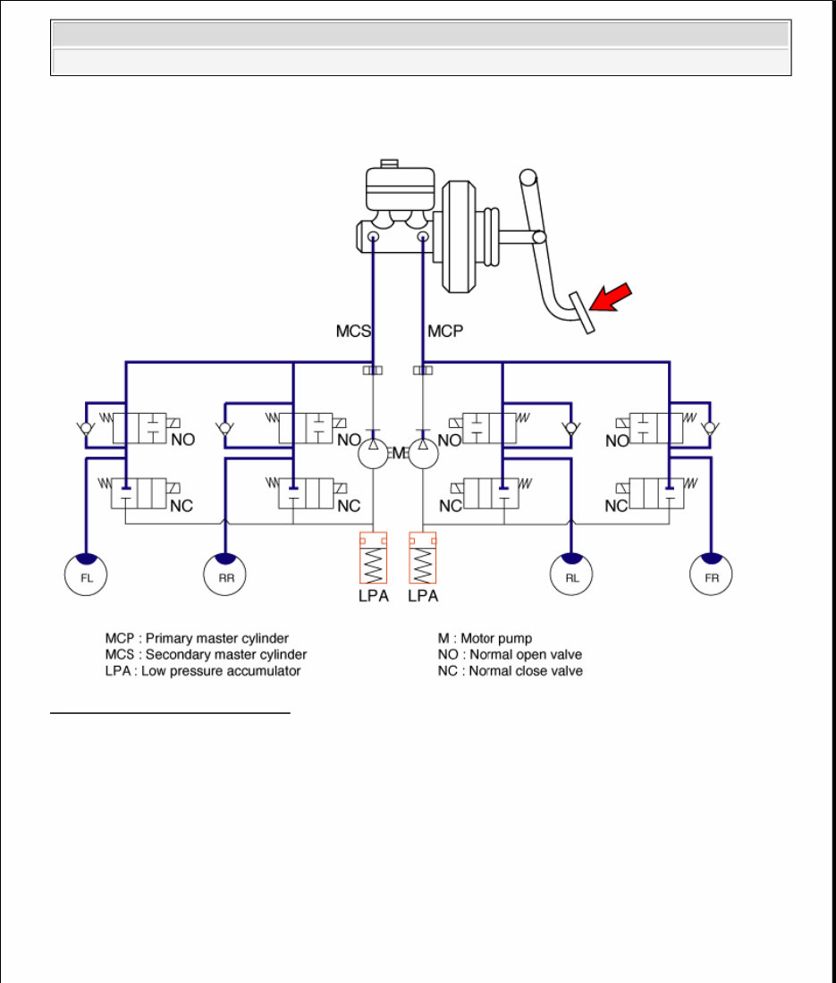
Hydraulic System Diagram Fig. 8: Hydraulic System Diagram Courtesy of KIA MOTORS AMERICA, INC. SCHEMATIC DIAGRAMS CIRCUIT DIAGRAM - ABS (1) 2009 Kia Borrego LX 2009-10 BRAKES ABS (Anti-Lock Brake System) - Borrego + 2010 Canadian
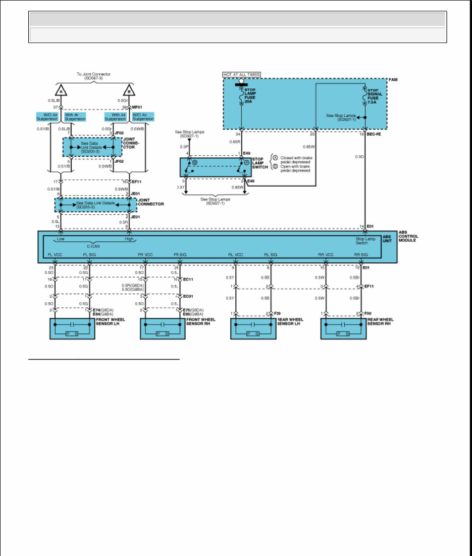
Fig. 9: ABS - Circuit Diagram (1 Of 3) Courtesy of KIA MOTORS AMERICA, INC. CIRCUIT DIAGRAM - ABS (2) 2009 Kia Borrego LX 2009-10 BRAKES ABS (Anti-Lock Brake System) - Borrego + 2010 Canadian
The repair service manual for Kia Borrego 2009 2010 is an essential resource for both professional technicians and do-it-yourself mechanics. It is designed to provide comprehensive guidance for maintaining and repairing the vehicle or engine. This manual is particularly suitable for individuals with basic knowledge in electrical and mechanical concepts.
It covers a wide range of topics including engine removal, wiring diagrams, general information, specifications, lubrication points, oil types, periodic maintenance, tune-up procedures, disassembly, reassembly, fuel and lubrication systems, electrical system, ignition, chassis, charging, starter, battery, switches, wheels, brakes, steering, suspension, axles, chassis assembly, servicing information, service data, wire/cable/hose routing, tools, tightening torques, complete engine service, fuel system service, gearbox, exhaust system, fault finding, clutch removal and installation, transmission, front suspension, bodywork, gearbox service, gearbox removal and installation, cooling system, detailed specifications, factory maintenance schedules, electrics, engine firing order, brake servicing procedures, U-joint service procedures, CV joint service procedures, timing chain service, exhaust service, and more.
The manual is available in PDF format, making it accessible for instant delivery and compatible with all versions of Windows and Mac. It provides full printable specifications and allows zoom in/out functionality. It is a valuable reference for anyone seeking to make informed decisions about maintaining and repairing Kia Borrego 2009 2010.