GROUP TAB LOCATOR Introduction 0 Lubrication & Maintenance 2 Suspension 3 Differential & Driveline 5 Brakes 6 Clutch 7 Cooling 8A Audio 8B Chime/Buzzer 8E Electronic Control Modules 8F Engine Systems 8G Heated Systems 8H Horn 8I Ignition Control 8J Instrument Cluster 8L Lamps 8N Power System 8O Restraints 8P Speed Control 8Q Vehicle Theft Security 8R Wipers/Washers 8W Wiring 9 Engine 11 Exhaust System 13 Frame & Bumpers 14 Fuel System 19 Steering 21 Transmission and Transfer Case 22 Tires/Wheels 23 Body 24 Heating & Air Conditioning 25 Emissions Control Component and System Index Service Manual Comment Forms (Rear of Manual)
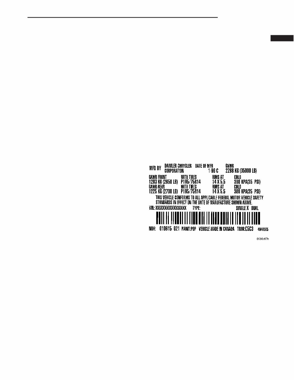
INTRODUCTION TABLE OF CONTENTS page page VEHICLE SAFETY CERTIFICATION LABEL DESCRIPTION .......................... 1 VEHICLE IDENTIFICATION NUMBER DESCRIPTION .......................... 1 VEHICLE EMISSION CONTROL INFORMATION (VECI) LABEL DESCRIPTION .......................... 2 BODY CODE PLATE DESCRIPTION BODY CODE PLATE .................... 3 INTERNATIONAL SYMBOLS DESCRIPTION .......................... 4 FASTENER IDENTIFICATION DESCRIPTION .......................... 5 FASTENER USAGE DESCRIPTION DESCRIPTION - FASTENER USAGE ........ 8 DESCRIPTION - THREADED HOLE REPAIR ..8 METRIC SYSTEM DESCRIPTION .......................... 8 TORQUE REFERENCES DESCRIPTION ......................... 10 VEHICLE SAFETY CERTIFICATION LABEL DESCRIPTION A vehicle safety certification label (Fig. 1) is attached to every DaimlerChrysler Corporation vehi- cle. The label certifies that the vehicle conforms to all applicable Federal Motor Vehicle Safety Standards. The label also lists: • Month and year of vehicle manufacture. • Gross Vehicle Weight Rating (GVWR). The gross front and rear axle weight ratings (GAWR’s) are based on a minimum rim size and maximum cold tire inflation pressure. • Vehicle Identification Number (VIN). • Type of vehicle. • Type of rear wheels. • Bar code. • Month, Day and Hour (MDH) of final assembly. • Paint and Trim codes. • Country of origin. The label is located on the driver-side door shut- face. VEHICLE IDENTIFICATION NUMBER DESCRIPTION The Vehicle Identification Number (VIN) plate is located on the lower windshield fence near the left A-pillar. The VIN contains 17 characters that provide data concerning the vehicle. Refer to the VIN decod- ing chart to determine the identification of a vehicle. The Vehicle Identification Number is also imprinted on the: • Vehicle Safety Certification Label. • Frame rail. To protect the consumer from theft and possible fraud the manufacturer is required to include a Check Digit at the ninth position of the Vehicle Iden- tification Number. The check digit is used by the manufacturer and government agencies to verify the authenticity of the vehicle and official documenta- tion. The formula to use the check digit is not released to the general public. Fig. 1 VEHICLE SAFETY CERTIFICATION LABEL - TYPICAL TJ INTRODUCTION 1
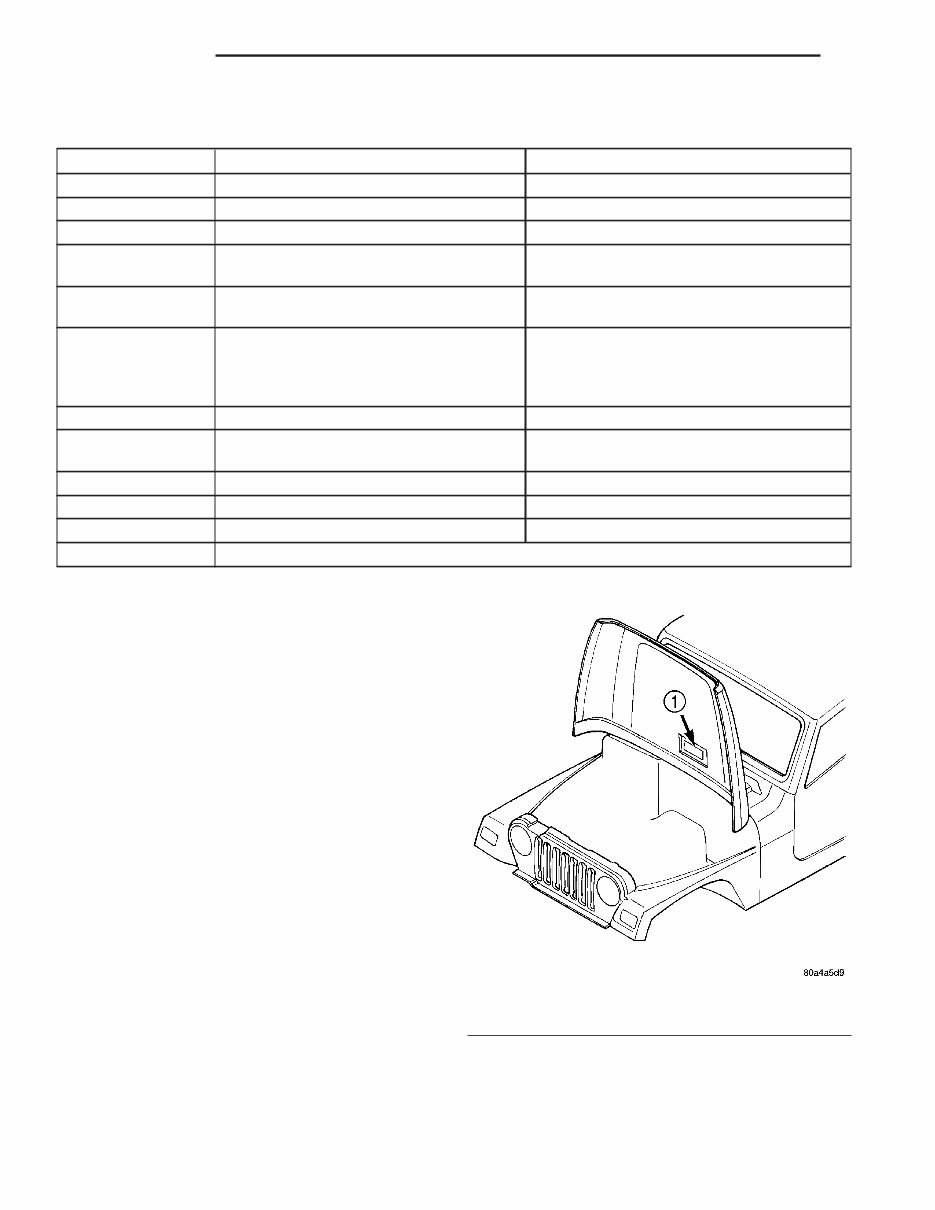
VEHICLE IDENTIFICATION NUMBER DECODING CHART POSITION INTERPRETATION CODE = DESCRIPTION 1 Country of Origin 1 = United States 2 Make J = Jeep 3 Vehicle Type 4 = MPV 4 Gross Vehicle Weight Rating E = 3001-4000 lbs. F = 4001-5000 lbs. 5 Vehicle Line A = Wrangler 4X4 (LHD) 4 = Wrangler 4X4 (RHD) 6 Series 2 = SE 3=X 4 = Sport 5 = Sahara 7 Body Style 9 = Open Body 8 Engine P = 2.4L Gasoline S = 4.0L Gasoline 9 Check Digit 0 through 9 or X 10 Model Year 3=2003 11 Assembly Plant P = Toledo #2 12 thru 17 Vehicle Build Sequence VEHICLE EMISSION CONTROL INFORMATION (VECI) LABEL DESCRIPTION All models have a Vehicle Emission Control Infor- mation (VECI) Label. DaimlerChrysler permanently attaches the label in the engine compartment (Fig. 2). It cannot be removed without defacing informa- tion and destroying the label. The label contains the vehicle’s emission specifica- tions and vacuum hose routings. All hoses must be connected and routed according to the label. The VECI label contains the following: • Engine family and displacement • Evaporative family • Emission control system schematic • Certification application • Engine timing specifications (if adjustable) • Idle speeds (if adjustable) • Spark plug and gap The label also contains an engine vacuum sche- matic. These labels are permanently attached and cannot be removed without defacing information and destroying label. Fig. 2 VECI Label Location 1 - VECI LABEL 2 INTRODUCTION TJ VEHICLE IDENTIFICATION NUMBER (Continued)
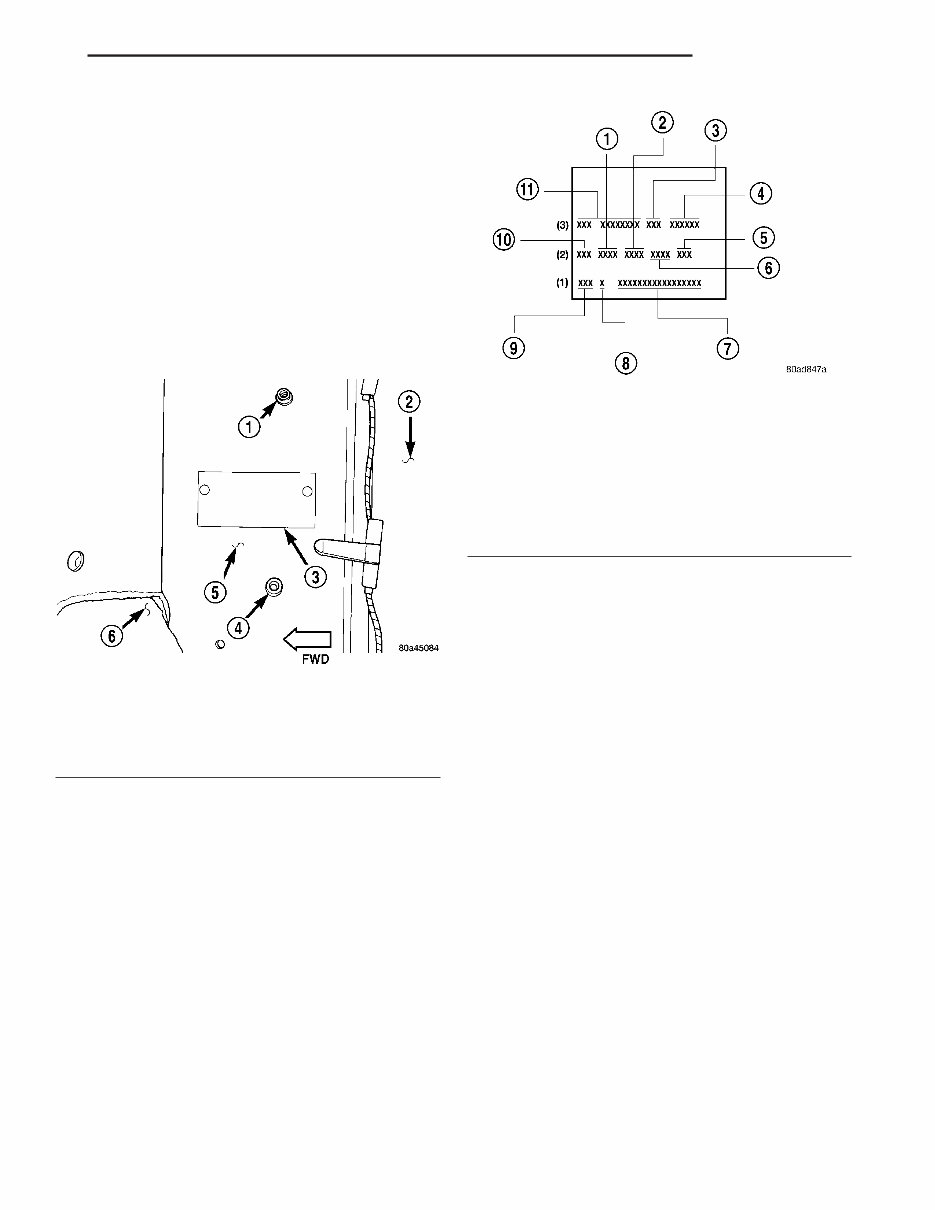
BODY CODE PLATE DESCRIPTION BODY CODE PLATE A metal body code plate is attached to the floor pan under the drivers seat (Fig. 3). Disengage the snaps attaching the carpet to the floor pan to read the information. There are seven lines of information on the body code plate. Lines 4, 5, 6, and 7 are not used to define service information. Information reads from left to right, starting with line 3 in the center of the plate to line 1 at the bottom of the plate (Fig. 4). The last code imprinted on a vehicle code plate will be followed by the imprinted word END. When two vehicle code plates are required, the last available spaces on the first plate will be imprinted with the letters CTD (for continued). When a second vehicle code plate is necessary, the first four spaces on each row will not be used because of the plate overlap. BODY CODE PLATE—LINE 3 DIGITS 1 THROUGH 12 Vehicle Order Number DIGITS 13, 14, AND 15 Roof • VJN = Soft Top White • VJU = Soft Top Spice • VJX = Soft Top Black • VKN = Hard Top White • VKU = Hard Top Spice • VKX = Hard Top Black DIGITS 16, 17, AND 18 Car Line Shell • TJJ = Wrangler (LHD) • TJU = Wrangler (RHD) DIGIT 19 Price Class • L = Wrangler (All) DIGITS 20 AND 21 Body Type • 77 = Wheel Base (93.4 in.) BODY CODE PLATE—LINE 2 DIGITS 1,2, AND 3 Paint Procedure DIGIT 4 Open Space DIGITS 5 THROUGH 8 Primary Paint (Refer to 23 - BODY/PAINT - SPECIFICATIONS) for color codes. DIGIT 9 Open Space Fig. 3 Body Code Plate Location 1 - SNAP 2 - REAR CARPET 3 - BODY CODE PLATE 4 - SNAP 5 - FLOOR PAN 6 - FRONT CARPET Fig. 4 Body Code Plate Decoding 1 - PRIMARY PAINT 2 - SECONDARY PAINT 3 - ROOF 4 - CAR LINE SHELL 5 - ENGINE 6 - TRIM 7 - VIN 8 - MARKET 9 - TRANSMISSION 10 - PAINT PROCEDURE 11 - VEHICLE ORDER NUMBER TJ INTRODUCTION 3
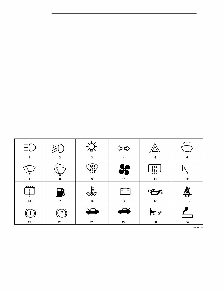
DIGITS 10 THROUGH 13 Secondary Paint DIGIT 14 Open Space DIGITS 15 THROUGH 18 Interior Trim Code DIGIT 19 Open Space DIGITS 20, 21, AND 22 Engine Code • ED1 = 2.4L 4 cyl. MPI Gasoline • ERH = 4.0L 6 cyl. MPI Gasoline BODY CODE PLATE—LINE 1 DIGITS 1, 2, AND 3 Transmission Codes • DDD = NV3550 5 - speed Manual • DDK = AX15 5 - speed Manual • DG6 = 42RLE 4 - speed Automatic DIGIT 4 Open Space DIGIT 5 Market Code • B = International DIGIT 6 Open Space DIGITS 7 THROUGH 23 Vehicle Identification Number (VIN) (Refer to VEHICLE DATA/VEHICLE INFORMA- TION/VEHICLE IDENTIFICATION NUMBER - DESCRIPTION) for breakdown of VIN code. INTERNATIONAL SYMBOLS DESCRIPTION The graphic symbols illustrated in the following International Control and Display Symbols Chart (Fig. 5) are used to identify various instrument con- trols. The symbols correspond to the controls and dis- plays that are located on the instrument panel. Fig. 5 INTERNATIONAL CONTROL AND DISPLAY SYMBOLS 1 High Beam 13 Rear Window Washer 2 Fog Lamps 14 Fuel 3 Headlamp, Parking Lamps, Panel Lamps 15 Engine Coolant Temperature 4 Turn Warning 16 Battery Charging Condition 5 Hazard Warning 17 Engine Oil 6 Windshield Washer 18 Seat Belt 7 Windshield Wiper 19 Brake Failure 8 Windshield Wiper and Washer 20 Parking Brake 9 Windscreen Demisting and Defrosting 21 Front Hood 10 Ventilating Fan 22 Rear hood (Decklid) 11 Rear Window Defogger 23 Horn 12 Rear Window Wiper 24 Lighter 4 INTRODUCTION TJ BODY CODE PLATE (Continued)
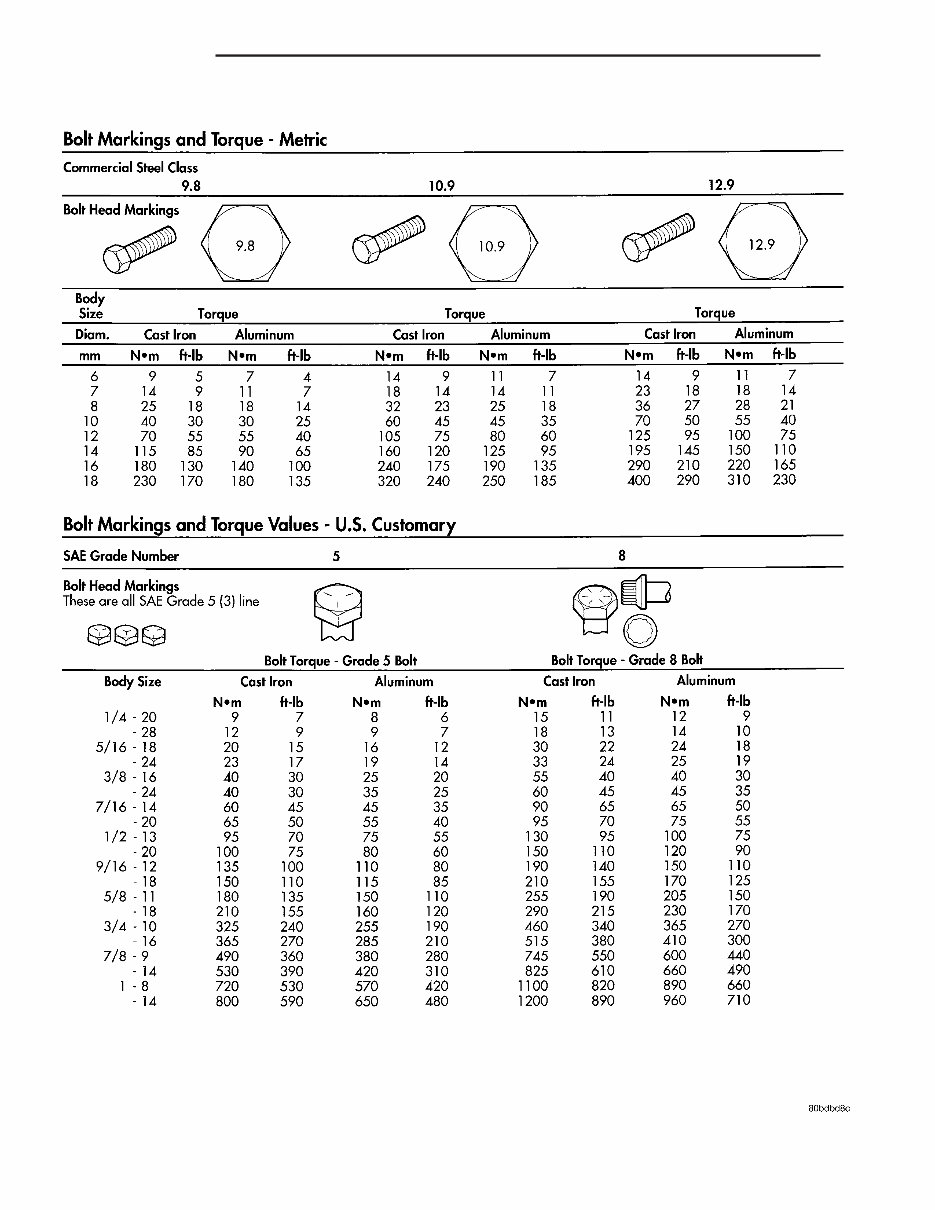
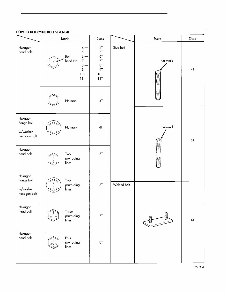
FASTENER IDENTIFICATION DESCRIPTION The SAE bolt strength grades range from grade 2 to grade 8. The higher the grade number, the greater the bolt strength. Identification is determined by the line marks on the top of each bolt head. The actual bolt strength grade corresponds to the number of line marks plus 2. The most commonly used metric bolt strength classes are 9.8 and 10.9. The metric strength class identification number is imprinted on the head of the bolt. The higher the class number, the greater the bolt strength. Some metric nuts are imprinted with a single-digit strength class on the nut face. Refer to the Fastener Identification and Fastener Strength Charts (Fig. 6) and (Fig. 7). TJ INTRODUCTION 5
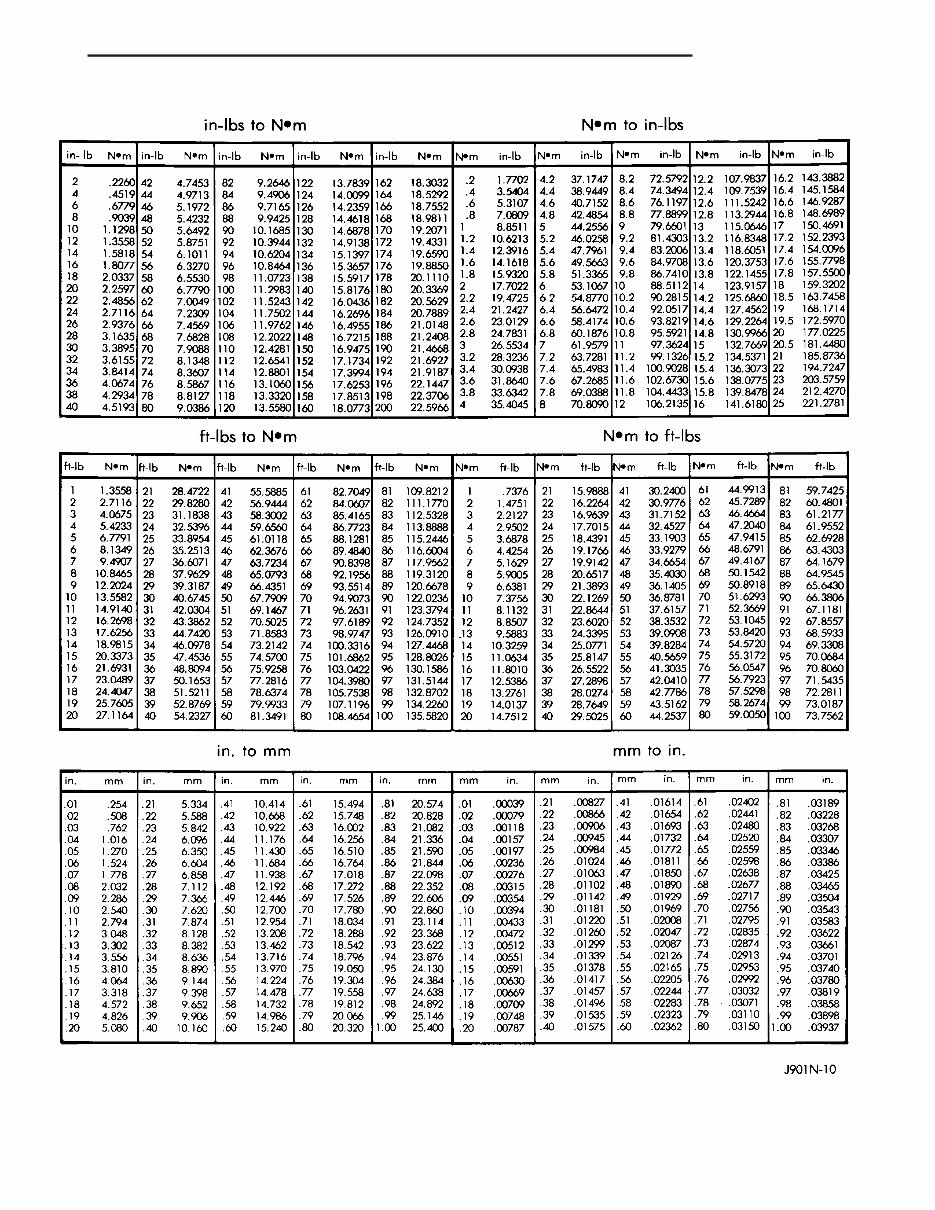
FASTENER USAGE DESCRIPTION DESCRIPTION - FASTENER USAGE WARNING: USE OF AN INCORRECT FASTENER MAY RESULT IN COMPONENT DAMAGE OR PER- SONAL INJURY. Fasteners and torque specifications references in this Service Manual are identified in metric and SAE format. During any maintenance or repair procedures, it is important to salvage all fasteners (nuts, bolts, etc.) for reassembly. If the fastener is not salvageable, a fastener of equivalent specification must be used. DESCRIPTION - THREADED HOLE REPAIR Most stripped threaded holes can be repaired using a Helicoilt. Follow the vehicle or Helicoilt recommen- dations for application and repair procedures. METRIC SYSTEM DESCRIPTION The metric system is based on quantities of one, ten, one hundred, one thousand and one million. The following chart will assist in converting metric units to equivalent English and SAE units, or vise versa. CONVERSION FORMULAS AND EQUIVALENT VALUES MULTIPLY BY TO GET MULTIPLY BY TO GET in-lbs x 0.11298 = Newton Meters (N·m) N·m x 8.851 = in-lbs ft-lbs x 1.3558 = Newton Meters (N·m) N·m x 0.7376 = ft-lbs Inches Hg (60° F) x 3.377 = Kilopascals (kPa) kPa x 0.2961 = Inches Hg psi x 6.895 = Kilopascals (kPa) kPa x 0.145 = psi Inches x 25.4 = Millimeters (mm) mm x 0.03937 = Inches Feet x 0.3048 = Meters (M) M x 3.281 = Feet Yards x 0.9144 = Meters M x 1.0936 = Yards mph x 1.6093 = Kilometers/Hr. (Km/h) Km/h x 0.6214 = mph Feet/Sec x 0.3048 = Meters/Sec (M/S) M/S x 3.281 = Feet/Sec mph x 0.4470 = Meters/Sec (M/S) M/S x 2.237 = mph Kilometers/ Hr. (Km/h) x 0.27778 = Meters/Sec (M/S) M/S x 3.600 Kilometers/Hr. (Km/h) COMMON METRIC EQUIVALENTS 1 inch = 25 Millimeters 1 Cubic Inch = 16 Cubic Centimeters 1 Foot = 0.3 Meter 1 Cubic Foot = 0.03 Cubic Meter 1 Yard = 0.9 Meter 1 Cubic Yard = 0.8 Cubic Meter 1 Mile = 1.6 Kilometers Refer to the Metric Conversion Chart to convert torque values listed in metric Newton- meters (N·m). Also, use the chart to convert between millimeters (mm) and inches (in.) (Fig. 8). 8 INTRODUCTION TJ
The Jeep Wrangler 2005 Factory Repair Service Manual is the ultimate resource for owners of the Jeep Wrangler model year 2005. This comprehensive manual provides detailed instructions and diagrams for repairing and maintaining your vehicle.
Whether you are a professional mechanic or a Jeep enthusiast, this manual will guide you through every step of the repair process. From routine maintenance tasks to complex engine repairs, you can trust the Jeep Wrangler 2005 Factory Repair Service Manual to provide accurate and reliable information.
Models Covered:
Jeep Wrangler 2005 Sport
Jeep Wrangler 2005 X
Jeep Wrangler 2005 Rubicon
Jeep Wrangler 2005 Sahara
With this manual, you can save time and money by performing repairs and maintenance yourself. No more costly trips to the mechanic or endless searching for answers online. The Jeep Wrangler 2005 Factory Repair Service Manual has everything you need to keep your vehicle running smoothly.