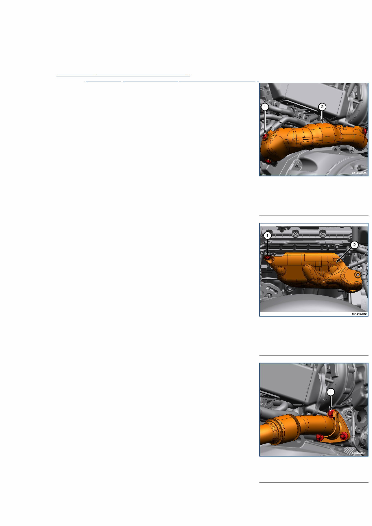
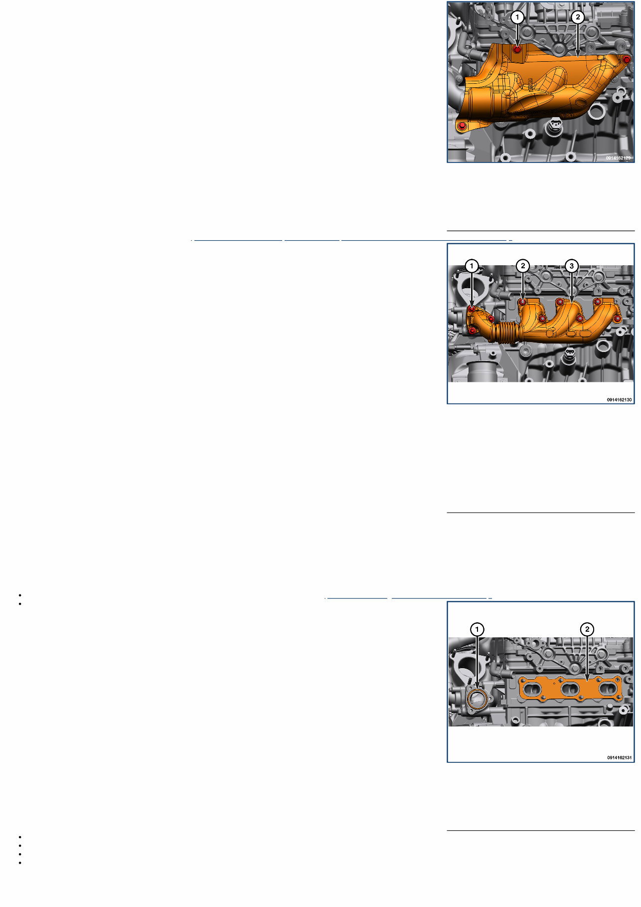
1 - Heat Shield Bolts 2 - Heat Shield 1 - Exhaust Manifold Heat Shield Bolt 2 - Exhaust Manifold Heat Shield 1 - Exhaust Manifold Pipe to Turbocharger Bolts 11 - Exhaust System / MANIFOLD, Exhaust / Removal and Installation LEFT BANK REMOVAL WARNING: The normal operating temperature of the exhaust system is very high. Therefore, never work around or attempt to service any part of the exhaust system until it has cooled. Special care should be taken when working near the catalytic converter. The temperature of the converter rises to a high level after a short period of engine operation time. 1. Remove the body (Refer to 23 - Body/Exterior/BODY/Removal and Installation) . 2. Remove the oil cooler adapter (Refer to 09 - Engine/Lubrication/ADAPTER, Oil Filter/Removal and Installation) . 3. Remove the heat shield bolts and the heat shield. 4. Remove the left exhaust manifold heat shield bolt and the left exhaust manifold heat shield. 5. Remove the exhaust manifold pipe to turbocharger bolts. 6. Remove the left exhausts manifold nuts and the left exhausts manifold.
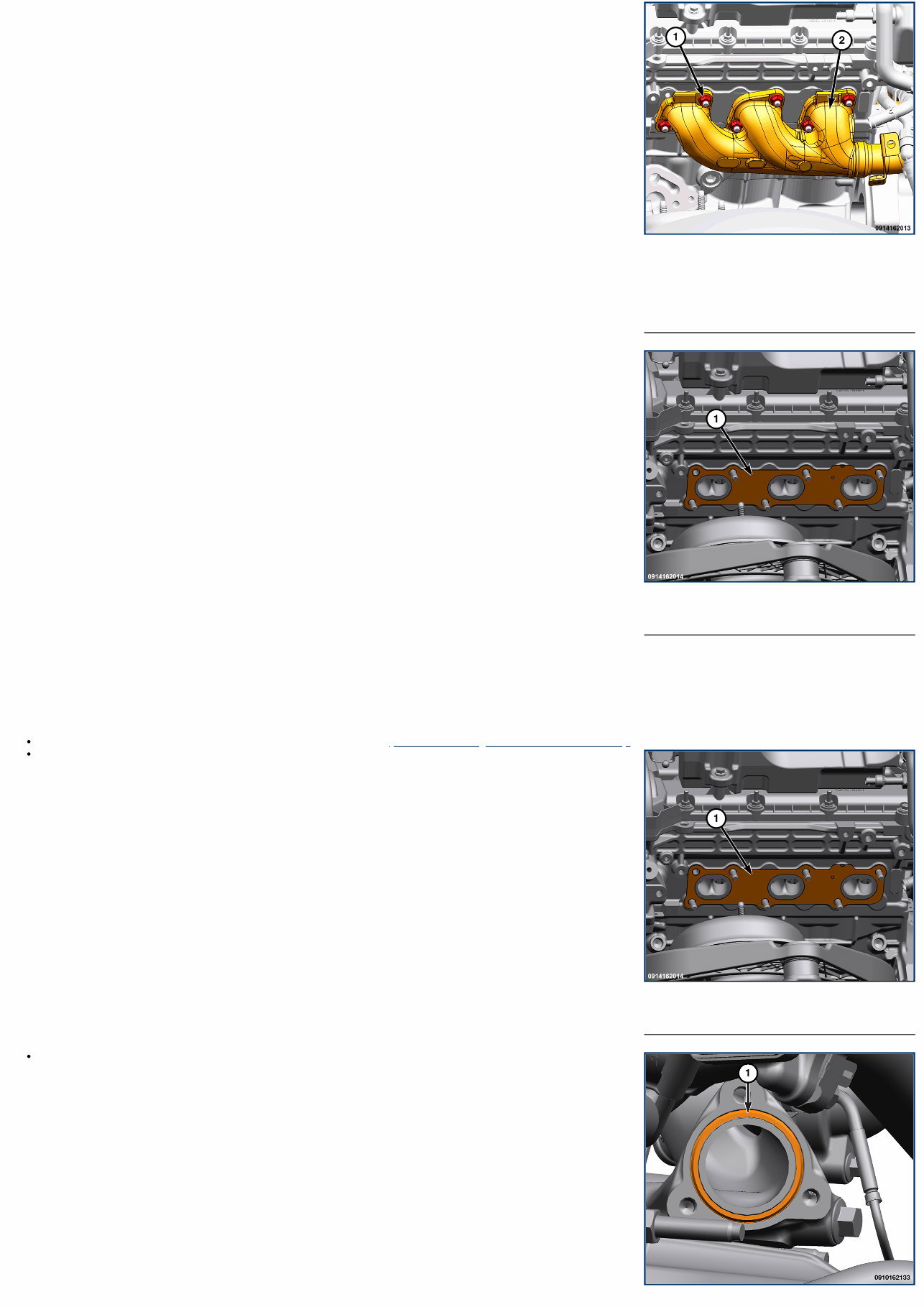
1 - Left Exhausts Manifold Nuts 2 - Left Exhausts Manifold 1 - Gasket 1 - Gasket 7. Remove and discard the gasket. INSTALLATION Follow the removal procedure in reverse for general reassembly of the components on the vehicle. The steps listed below are calling out specific procedures that should be followed during installation. Clean the cylinder head and exhaust manifold sealing surfaces (Refer to 09 - Engine - Standard Procedure) . Install a NEW exhaust manifold gasket onto the cylinder head. Install a NEW gasket to the left side of turbocharger.
1 - Gasket Install the exhaust manifold and tighten the exhaust manifold nuts using the tightening sequence shown in the torque table to proper torque specifications. Install the exhaust manifold to turbocharger bolts and tighten using the tightening sequence shown in the torque table to proper torque specifications. TORQUE SPECIFICATIONS - EXHAUST - 3.0L DIESEL
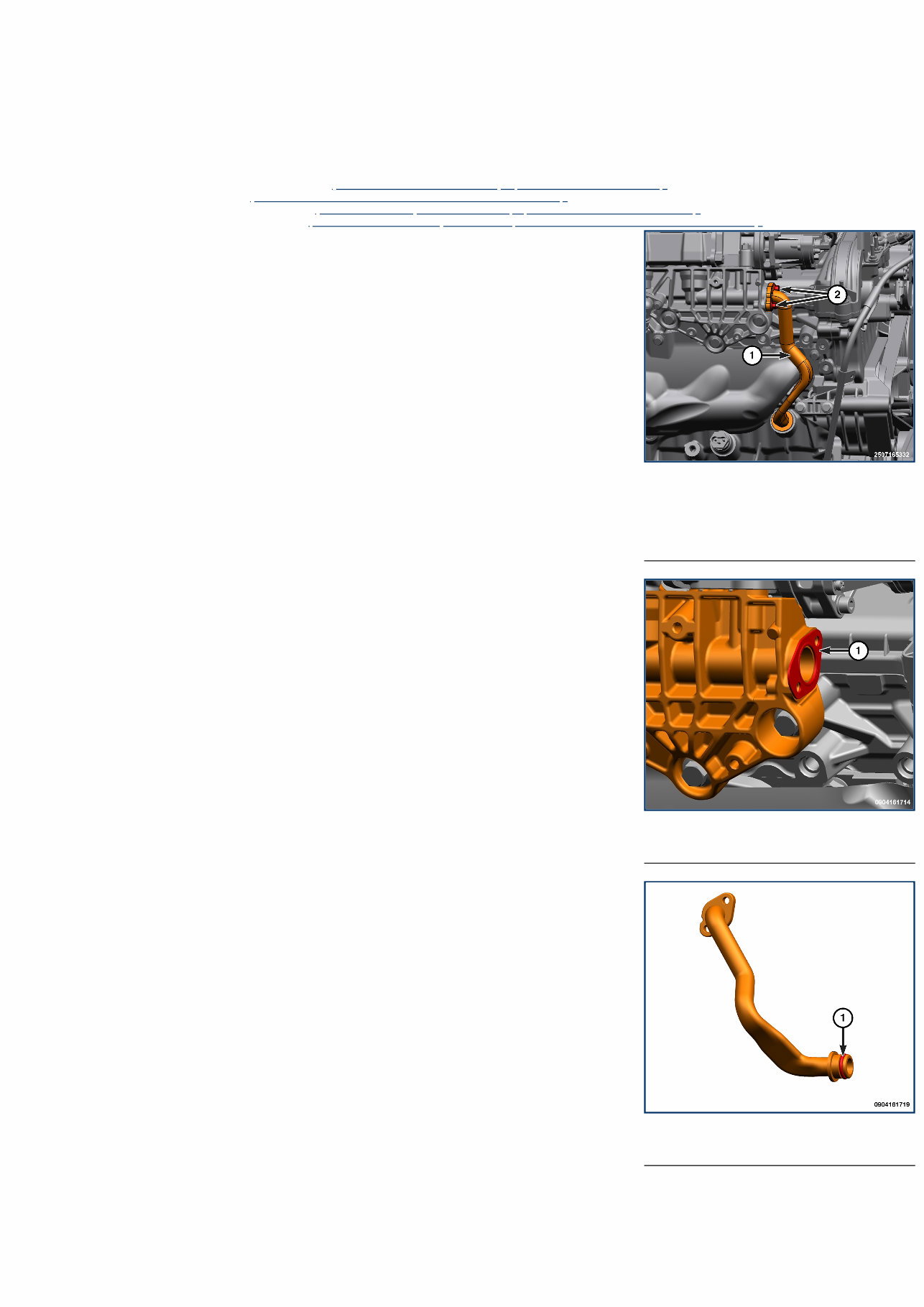
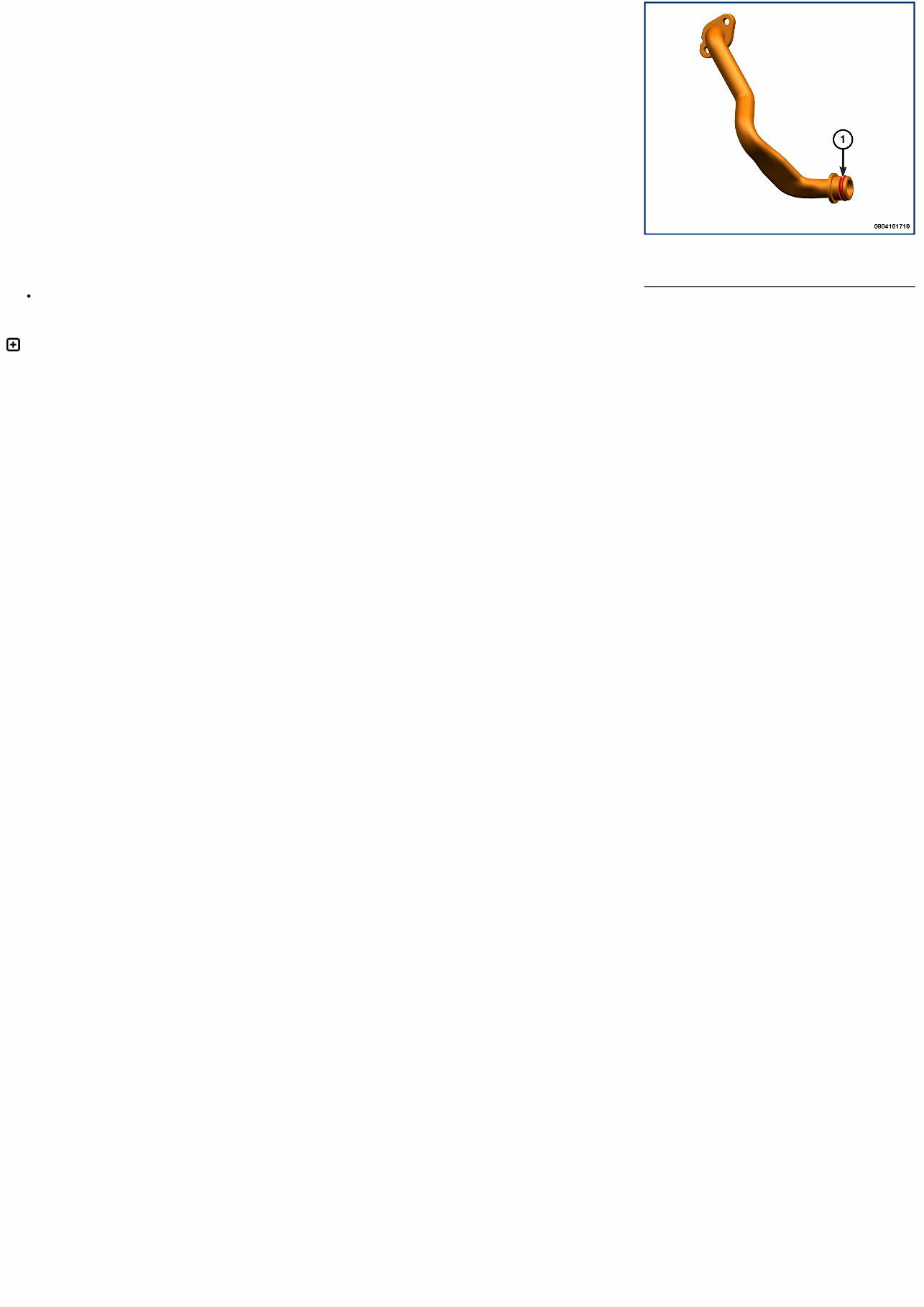
1 - EGR Cooler Coolant Tube 2 - EGR Cooler Coolant Tube Bolts 1 - Coolant Tube Gasket 1 - O-ring 11 - Exhaust System / MANIFOLD, Exhaust / Removal and Installation RIGHT BANK REMOVAL WARNING: The normal operating temperature of the exhaust system is very high. Therefore, never work around or attempt to service any part of the exhaust system until it has cooled. Special care should be taken when working near the catalytic converter. The temperature of the converter rises to a high level after a short period of engine operation time. 1. Disconnect and isolate the negative battery cable(s) (Refer to 08 - Electrical/Battery System/Standard Procedure) . 2. Remove the right front tire and wheel (Refer to 22 - Tires and Wheels/Removal and Installation) . 3. Remove the right front wheel house splash shield (Refer to 23 - Body/Exterior/SHIELD, Splash/Removal and Installation) . 4. Remove the Diesel Particulate Filter (DPF) elbow (Refer to 11 - Exhaust System/FILTER, Diesel Particulate/Removal and Installation) . 5. Remove the EGR cooler coolant tube bolts and the EGR cooler coolant tube. 6. Remove and DISCARD the coolant tube gasket. 7. Remove and DISCARD the coolant tube O-ring. 8. Remove the right exhaust manifold heat shield bolts and the right exhaust manifold heat shield.
1 - Right Exhaust Manifold Heat Shield Bolts 2 - Right Exhaust Manifold Heat Shield 1 - Right Exhaust Manifold To Turbocharger Bolts 2 - Right Exhaust Manifold Nuts 3 - Right Exhaust Manifold 1 - Gasket 2 - Gasket 9. Remove the exhaust pressure sensor tube (Refer to 11 - Exhaust System/SENSOR, Exhaust Pressure/Removal and Installation) . 10. Remove the right exhaust manifold to turbocharger bolts. 11. Remove the right exhaust manifold nuts and the right exhaust manifold. INSTALLATION Follow the removal procedure in reverse for general reassembly of the components on the vehicle. The steps listed below are calling out specific procedures that should be followed during installation. Clean the cylinder head, exhaust manifold and turbocharger sealing surfaces (Refer to 09 - Engine - Standard Procedure) . Install a NEW gaskets onto the turbocharger and cylinder head. Install the exhaust manifold and tighten the exhaust manifold nuts using the tightening sequence shown in the torque table to proper torque specifications. Install the exhaust manifold to turbocharger bolts and tighten using the tightening sequence shown in the torque table to proper torque specifications. Lubricate and install a NEW O-ring seal on the coolant tube. Using a NEW gasket, install the EGR cooler coolant tube and tighten the coolant tube bolts to the proper torque specifications.
1 - O-ring Start the engine and check for leaks. TORQUE SPECIFICATIONS - EXHAUST - 3.0L DIESEL
11 - Exhaust System / FILTER, Diesel Particulate / Standard Procedure STANDARD PROCEDURE - STATIONARY DESOOT WARNING: Due to the fact that the vehicle may be left unattended for up to one hundred (100) minutes during this procedure, every precautionary measure must be taken to ensure that the vehicle cannot be stolen and that no person comes in contact with the hot exhaust or hot exhaust gases during the procedure. NOTE: The fuel minimum specification to run the test is 1/4 of a tank of fuel. 1. Fill the vehicle with three (3) gallons of Ultra Low Sulfur diesel fuel to perform the procedure. NOTE: In order for Stationary De-Soot to begin, the vehicle must be parked with the parking brake engaged, be at normal operating temperature, and have at least three gallons of fuel. If any of these conditions are violated after Stationary De-Soot begins, or if the brake or accelerator pedal is pressed, Stationary De-Soot will abort. 2. Position the vehicle on a NONFLAMMABLE surface such as concrete. WARNING: Exhaust temperatures will be extremely high. Do not perform this procedure on flammable surfaces such as asphalt, grass, etc. or adjacent to property that may be damaged by the exhaust gases, or in a location where individuals may be required to pass adjacent to the exhaust. 3. Position the shift lever in Park or Neutral. 4. Mark an area 12 feet (3.66 meters) by 12 feet (3.66 meters) surrounding the exhaust outlet. The exhaust outlet should be six feet from the fore and aft ends of the marked off area. NOTE: Ensure that the “HOT EXHAUST” labels are facing outward. 5. If not already performed, connect the Diagnostic Scan Tool to the vehicle. 6. Start the engine. 7. Power ON the Diagnostic Scan Tool. 8. Scroll to the Powertrain Control Module (PCM) menu. 9. Select Service Diesel Particulate Filter Regeneration. NOTE: During Stationary De-Soot, engine RPM will be elevated to 2,500 RPM. When the engine RPM returns to normal idle, the Stationary De-Soot has completed or aborted. 10. Initiate Stationary De-Soot. NOTE: Stationary De-Soot may take up to 30 minutes to complete. The scan tool must remained connected during the stationary desoot. When the desoot is finished the scan tool will report a successful regen. 11. Stationary De-Soot will automatically abort once the cycle is complete. If Stationary De-Soot needs to be aborted prior to the end of the cycle, any of the following manual methods can be used: Turning the ignition OFF Depressing the brake pedal Moving the PRNDL from P/N to D/R 12. Once Stationary De-Soot is complete, remove the antitheft device. 13. Using the scan tool, perform DPF Reset Option function found under MISCELLANEOUS FUNCTIONS. 14. Once the regeneration is complete, the vehicle needs to be driven above 86 km/h (55 mph) for 15 minutes to allow the DPF differential pressure sensor to get a clear reading.
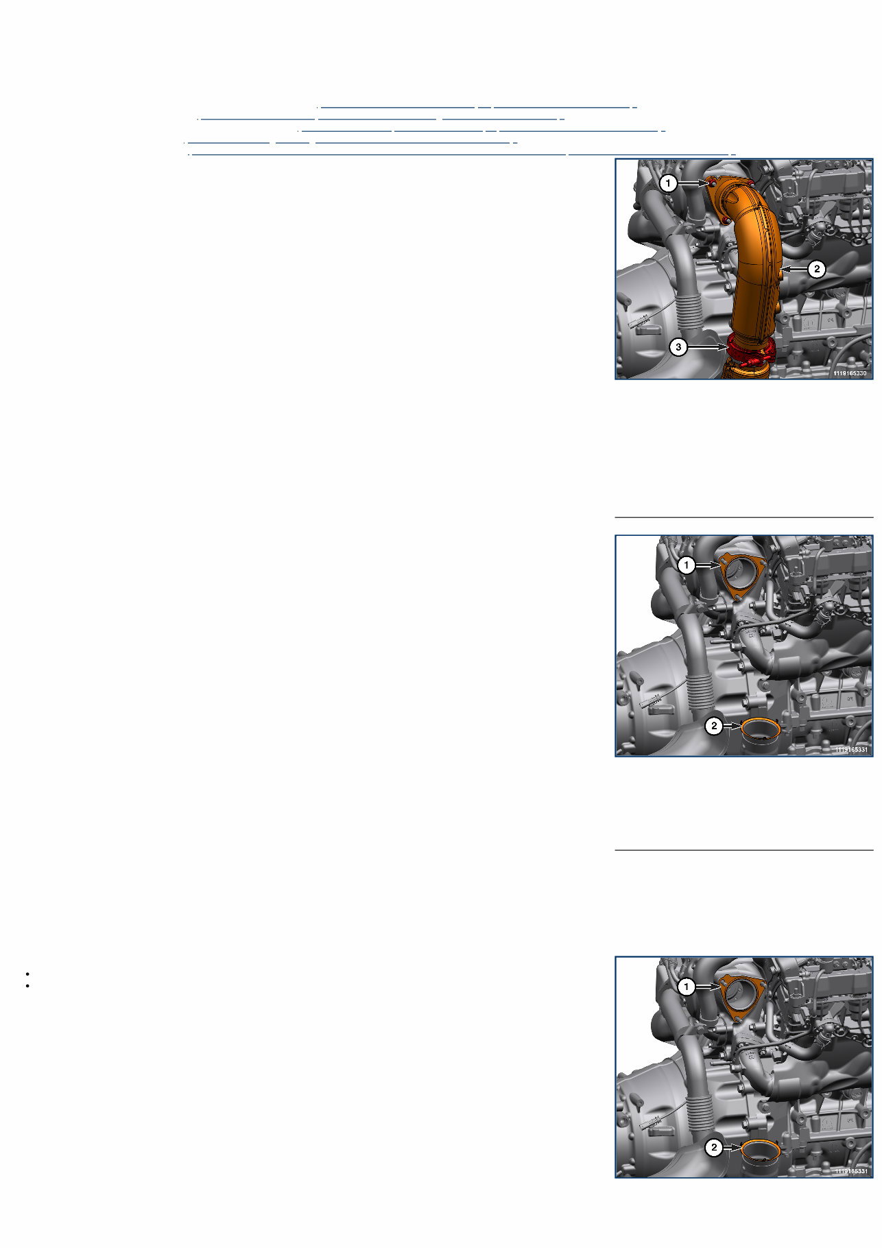
1 - Diesel Particulate Filter Inlet Elbow Nuts 2 - Diesel Particulate Filter Inlet Elbow 3 - Diesel Particulate Filter Inlet Elbow Clamp 1 - Flange Gasket 2 - Lower Flange Gasket 1 - Flange Gasket 11 - Exhaust System / FILTER, Diesel Particulate / Removal and Installation DIESEL PARTICULATE FILTER ELBOW REMOVAL 1. Disconnect and isolate the negative battery cable(s) (Refer to 08 - Electrical/Battery System/Standard Procedure) . 2. Raise and support the vehicle (Refer to 04 - Vehicle Quick Reference/Hoisting - Standard Procedure) . 3. Remove the right front wheelhouse splash shield (Refer to 23 - Body/Exterior/SHIELD, Splash/Removal and Installation) . 4. Remove the oxygen sensor (Refer to 09 - Engine/Engine Sensors/Removal and Installation) . 5. Remove the NOx sensor 1/1 (Refer to 25 - Emissions Control/Diesel Exhaust Fluid Emissions/SENSOR, NOx/Removal and Installation) . 6. Remove the Diesel Particulate Filter (DPF) inlet elbow clamp. 7. Remove DPF inlet elbow nuts and the DPF inlet elbow. 8. Remove and discard flange gasket. 9. Remove the discard the lower flange gasket. INSTILLATION Follow the removal procedure in reverse for general reassembly of the components on the vehicle. The steps listed below are calling out specific procedures that should be followed during installation. Install a NEW lower flange gasket. Install a NEW gasket to turbocharger flange.
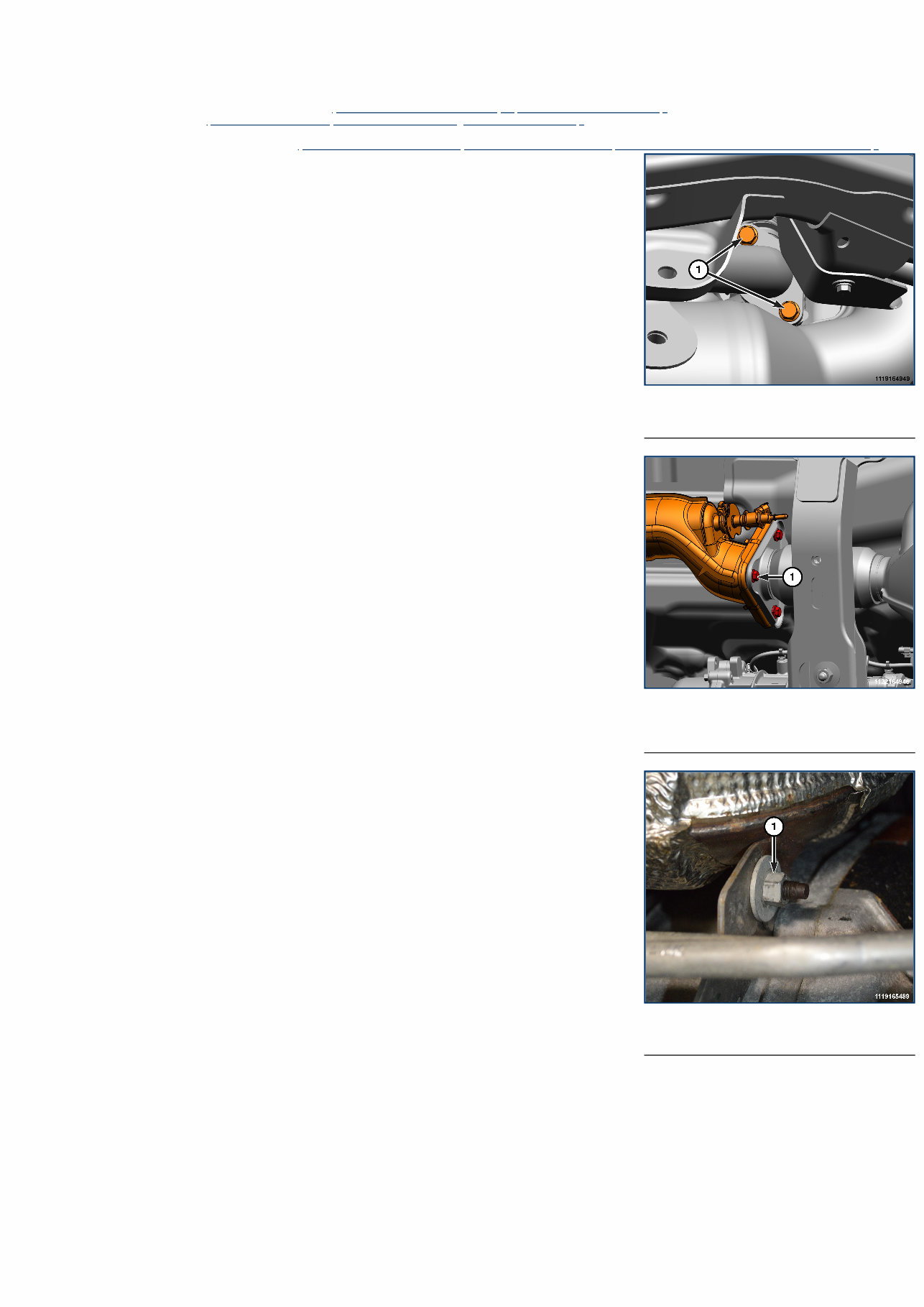
1 - Low Pressure EGR Tube Bolts 1 - Diesel Particulate Filter to Selective Catalytic Reduction Catalyst Bolts 1 - Steady Rest Bracket Nut 11 - Exhaust System / FILTER, Diesel Particulate / Removal and Installation DIESEL PARTICULATE FILTER REMOVAL 1. Disconnect and isolate the negative battery cable(s) (Refer to 08 - Electrical/Battery System/Standard Procedure) . 2. Raise and support the vehicle (Refer to 04 - Vehicle Quick Reference/Hoisting/Standard Procedure) . 3. Saturate the necessary fasteners with Mopar® Rust Inhibitor. Allow 5 minutes for penetration. 4. Remove the front reinforcement crossmember (Refer to 13 - Frame and Bumpers/Frame/CROSSMEMBER, Front Reinforcement/Removal and Installation) . 5. Remove the Low Pressure (LP) EGR tube bolts. 6. Position a jack stand under the DPF. 7. Remove the Diesel Particulate Filter (DPF) to Selective Catalytic Reduction (SCR) catalyst bolts. 8. Remove the steady rest bracket nut. 9. Remove the DPF inlet elbow clamp.
Keep Your 2023 Jeep Wrangler Running Smoothly And Efficiently With This Comprehensive Service & Repair Manual. Whether You'Re A Seasoned Mechanic Or A Diy Enthusiast, This Manual Provides You With All The Necessary Information And Procedures To Troubleshoot And Fix Any Issues With Your Vehicle.
Don'T Wait For Problems To Arise Before Taking Care Of Your Vehicle. Regular Maintenance Is Essential For Keeping Your Jeep Wrangler In Top Condition. Even With Proper Care, Some Parts May Eventually Wear Out And Require Replacement. This Repair Manual Has You Covered With The Manufacturer'S Recommended Troubleshooting Charts And Replacement Procedures.
Featuring Step-By-Step Instructions, Clear Images, And Exploded-View Illustrations, This Manual Is User-Friendly And Easy To Follow. There'S No Need To Spend Hours Flipping Through Endless Pages To Find The Information You Need. Everything Is Conveniently Organized For Quick Access, Saving You Time And Hassle.
With This Manual, You Can Save On Repairs And Increase Your Vehicle'S Reliability. No More Expensive Trips To The Repair Shop; You Can Handle The Maintenance And Repairs Yourself. Plus, With A Digital Copy, You Can Carry It With You Wherever You Go, Whether On Your Computer, Tablet, Or Smartphone. And If You Prefer A Physical Copy, Simply Print It Out.
This Service & Repair Manual Is Compatible With All Electronic Devices And Only Requires Adobe Reader (Available For Free) To Access. It'S Available In English, Making It Accessible To A Wide Range Of Users. Take Control Of Your Vehicle'S Maintenance And Repairs With This Comprehensive Manual For The 2023 Jeep Wrangler.






 Lifetime Access




