2020 Jeep Wrangler 2.0L I4 DOHC Di Turbo W-ESS Service & Repair Manual
What's Included?
Lifetime Access
Fast Download Speeds
Online & Offline Access
Access PDF Contents & Bookmarks
Full Search Facility
Print one or all pages of your manual
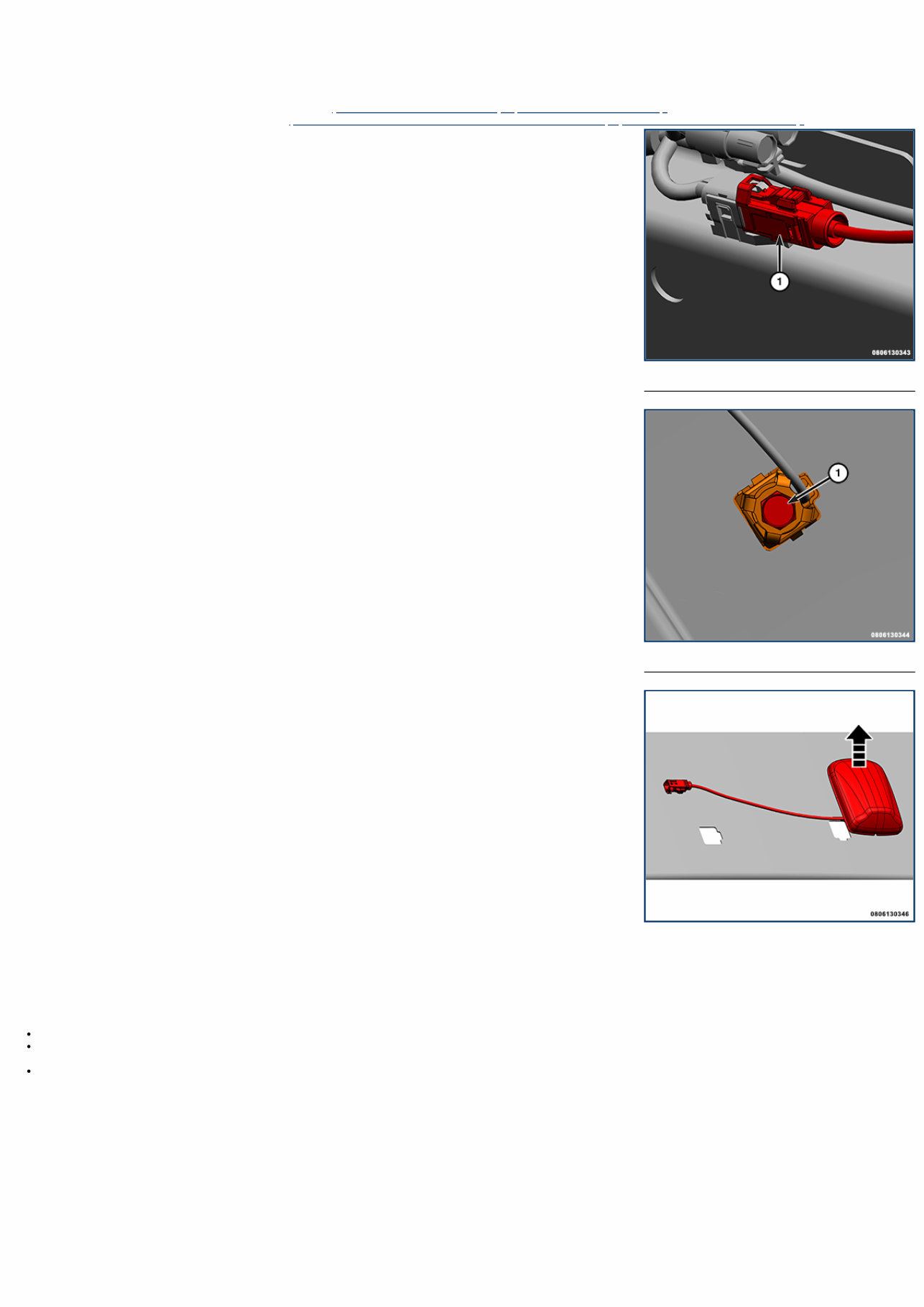
1 - Wire Harness Connector 1 - Mounting Retainer 08 - Electrical / 8A - Audio/Video/Entertainment/Connectivity / ANTENNA, Satellite, Audio / Removal and Installation SATELLITE ANTENNA REMOVAL 1. Disconnect and isolate the negative battery cable(s) (Refer to 08 - Electrical/Battery System/Standard Procedure) . 2. Remove the sport bar speaker pod assembly (Refer to 08 - Electrical/8A - Audio and Video/ENCLOSURE, Speaker/Removal and Installation) . 3. Disconnect the wire harness connector. 4. Remove the antenna mounting retainer. 5. From inside the vehicle, using a flat bladed tool, press one of the two plastic retaining tabs on the antenna stud. Push up on one side of the antenna stud, press the other plastic retaining tab and remove the antenna from the sport bar. INSTALLATION Follow the removal procedure in reverse for general reassembly of the components on the vehicle. The steps listed below are calling out specific procedures that should be followed during installation. A new silver clip (with four legs) must be used if the same antenna is being re-installed. Insert the wire harness through the hole in sport bar. Press the antenna into position until both retainers on the antenna stud and the locator stud engage into position in the sport bar. Tighten the fastener securely.
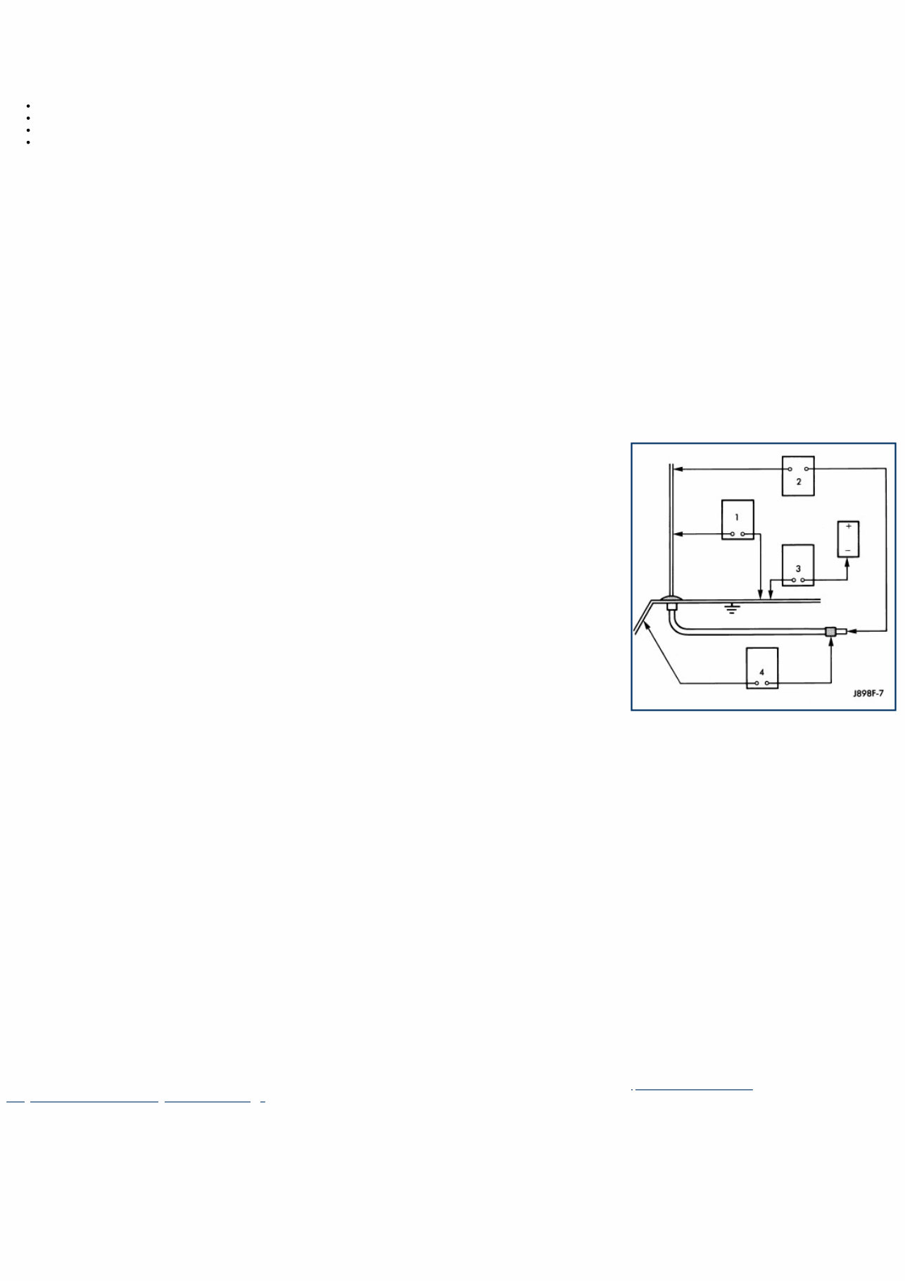
08 - Electrical / 8A - Audio/Video/Entertainment/Connectivity / BODY AND CABLE, Antenna / Diagnosis and Testing DIAGNOSIS AND TESTING - ANTENNA BODY AND CABLE The following four tests are used to diagnose the antenna with an ohmmeter: TEST 1 – Mast to ground test TEST 2 – Tip-of-mast to tip-of-conductor test TEST 3 – Body ground to battery ground test TEST 4 – Body ground to antenna coaxial cable shield test. WARNING: To avoid serious or fatal injury on vehicles equipped with airbags, disable the Supplemental Restraint System (SRS) before attempting any steering wheel, steering column, airbags, airbag curtains, knee blocker, seat belt tensioner, impact sensor or instrument panel component diagnosis or service. Disconnect the Intelligent Battery Sensor (IBS)/negative battery cable assembly from the negative battery post, then wait two minutes for the system capacitor to discharge before performing further diagnosis or service. This is the only sure way to disable the SRS. Failure to take the proper precautions could result in accidental airbag deployment. The ohmmeter test lead connections for each test are shown in the illustration. NOTE: This vehicle has a two-piece radio antenna coaxial cable. Tests 2 and 4 must be conducted in two steps to isolate an antenna cable problem. First, test the primary antenna cable (located between the antenna body and the secondary cable) from the coaxial cable connector under the right end of the instrument panel near the right cowl side inner panel to the antenna body. Then, test the secondary antenna cable (instrument panel antenna cable) from the coaxial cable connector under the right end of the instrument panel near the right cowl side inner panel to the coaxial cable connector at the radio. TEST 1 – Test 1 determines if the antenna mast is insulated from ground. Proceed as follows: 1. Disconnect and isolate the antenna coaxial cable connector under the right end of the instrument panel near the right cowl side inner panel. 2. Touch one ohmmeter test lead to the tip of the antenna mast. Touch the other test lead to the antenna body. Check the ohmmeter reading for continuity. 3. There should be no continuity. If OK, go to Test 2. If not OK, replace the shorted antenna body and cable. TEST 2 – Test 2 checks the antenna conductor components for an open circuit. This test should be performed first on the entire antenna circuit, from the antenna mast to the center conductor of the coaxial cable connector at the radio. If an open circuit is detected, each of the three antenna conductor components (antenna mast, antenna body and primary cable unit, instrument panel antenna secondary cable) should be isolated and tested individually to locate the exact component that is the source of the open circuit. To begin this test, proceed as follows: 1. Disconnect the instrument panel (secondary) antenna cable coaxial connector from the back of the radio. 2. Touch one ohmmeter test lead to the tip of the antenna mast. Touch the other test lead to the center conductor pin of the instrument panel antenna cable coaxial connector for the radio. Check the ohmmeter reading for continuity. 3. There should be continuity. The ohmmeter should register only a fraction of an ohm resistance. High or infinite resistance indicates a damaged or open antenna conductor. If OK, go to Test 3. If not OK, isolate and test each of the individual antenna conductor components. Replace only the ineffective antenna conductor component. TEST 3 – Test 3 checks the condition of the vehicle body ground connection. To begin this test, proceed as follows: 1. This test must be performed with the battery positive cable disconnected from the battery. Disconnect and isolate both battery cables, negative cable first. 2. Reconnect the battery negative cable. 3. Touch one ohmmeter test lead to a good clean ground point on the vehicle right fender panel. Touch the other test lead to the battery negative terminal post. Check the ohmmeter reading for continuity. 4. There should be continuity. The ohmmeter should register less than one ohm resistance. High or infinite resistance indicates a loose, corroded or damaged connection between the battery negative terminal and the vehicle body. If OK, go to Test 4. If not OK, check the battery negative cable connection to the vehicle body and the radio noise suppression ground strap connections to the engine and the vehicle body for being loose or corroded. Clean or tighten these connections as required. TEST 4 – Test 4 checks the condition of the connection between the antenna coaxial cable shield and the vehicle body ground as follows: 1. Disconnect and isolate the antenna coaxial cable connector under the right end of the instrument panel near the right cowl side inner panel. 2. Touch one ohmmeter test lead to a good clean ground point on the vehicle right fender panel. Touch the other test lead to the outer crimp on the antenna coaxial cable connector under the right end of the instrument panel near the right cowl side inner panel. Check the ohmmeter reading for continuity. 3. There should be continuity. The ohmmeter should register less than one ohm resistance. High or infinite resistance indicates a loose, corroded or damaged connection between the antenna body and the vehicle body or between the antenna body and the antenna coaxial cable shield. If not OK, clean the antenna body to right fender panel mating surfaces and tighten the antenna mounting nut to specifications. 4. Check the resistance again with an ohmmeter. If the resistance is still more then one ohm, replace the ineffective antenna body and cable. For additional diagnosis of an AM/FM reception issue, perform the POOR OR NO AM/FM AUDIO RECEPTION test. (Refer to 29 - Non-DTC Diagnostics/Audio/Video/Diagnosis and Testing) .
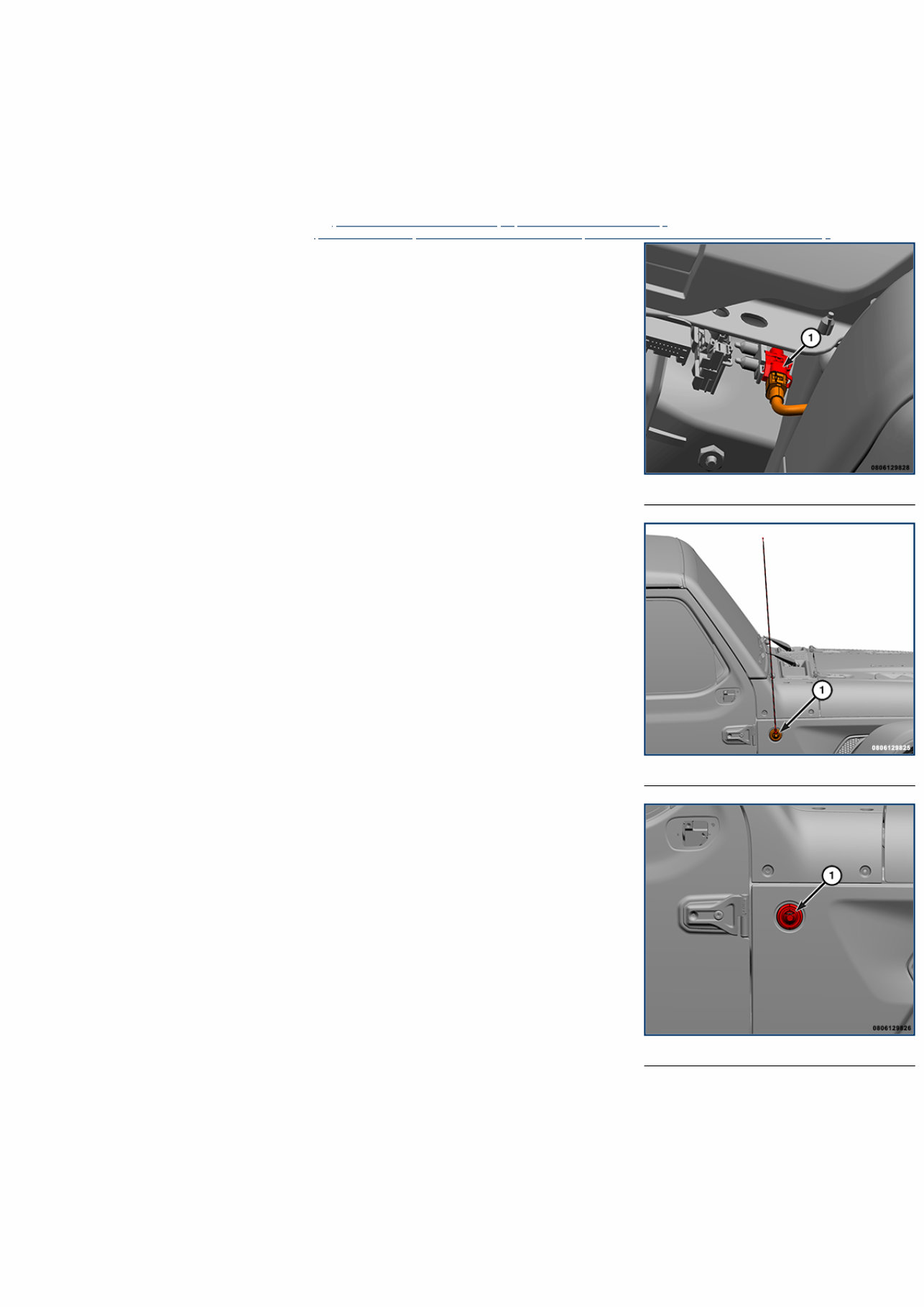
1 - Cable Connector 1 - Antenna Base 1 - Trim Cover 08 - Electrical / 8A - Audio/Video/Entertainment/Connectivity / BODY AND CABLE, Antenna / Removal and Installation BODY AND CABLE ANTENNA REMOVAL WARNING: To avoid serious or fatal injury on vehicles equipped with airbags, disable the Supplemental Restraint System (SRS) before attempting any steering wheel, steering column, airbags, airbag curtains, knee blocker, seat belt tensioner, impact sensor or instrument panel component diagnosis or service. Disconnect the Intelligent Battery Sensor (IBS)/negative battery cable assembly from the negative battery post, then wait two minutes for the system capacitor to discharge before performing further diagnosis or service. This is the only sure way to disable the SRS. Failure to take the proper precautions could result in accidental airbag deployment. 1. Disconnect and isolate the negative battery cable(s) (Refer to 08 - Electrical/Battery System/Standard Procedure) . 2. Remove the glove box from the instrument panel (Refer to 23 - Body/Instrument Panel/GLOVE BOX, Instrument Panel/Removal and Installation) . 3. Reach through the instrument panel glove box opening to unplug the antenna coaxial cable connector. 4. Unscrew the antenna mast from the antenna body base on the right outer cowl side panel. 5. Using a trim stick C-4755 or equivalent, gently pry the edge of the antenna base trim cover to unsnap it from the antenna body base. 6. Remove the fasteners that secure the antenna body base to the right outer cowl side panel.
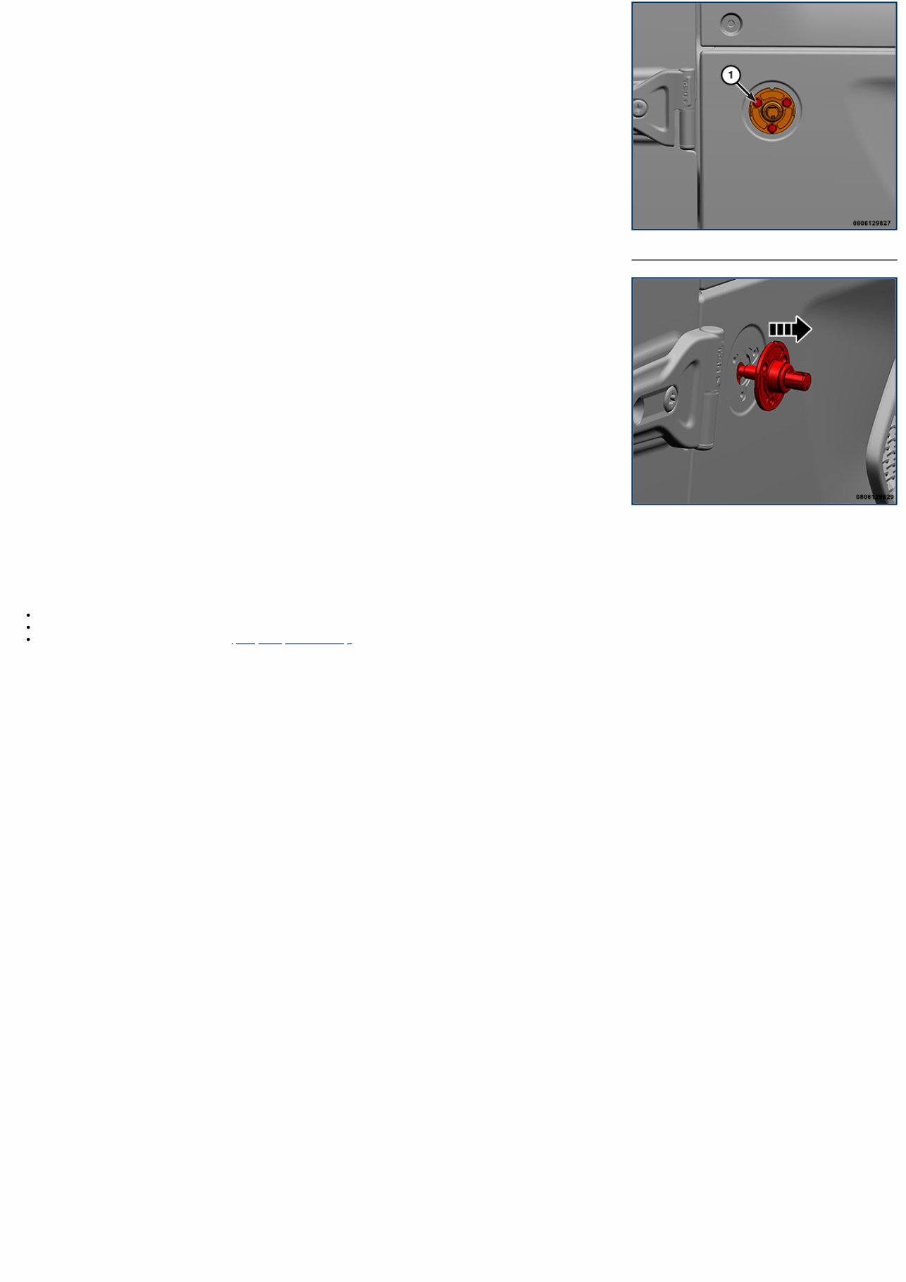
1 - Fastener 7. From inside the passenger compartment, push the coaxial cable grommet on the antenna body half of the coaxial cable out through the hole in the right inner cowl side panel. 8. From the outside of the vehicle, pull the antenna body base and cable assembly out through the hole in the right outer cowl side panel. INSTALLATION Follow the removal procedure in reverse for general reassembly of the components on the vehicle. The steps listed below are calling out specific procedures that should be followed during installation. Tighten antenna mast securely. Make certain that the antenna mast is fully seated on antenna base and that there is no gap between the mast and base. Tighten the fasteners to the proper (Torque Specification) .
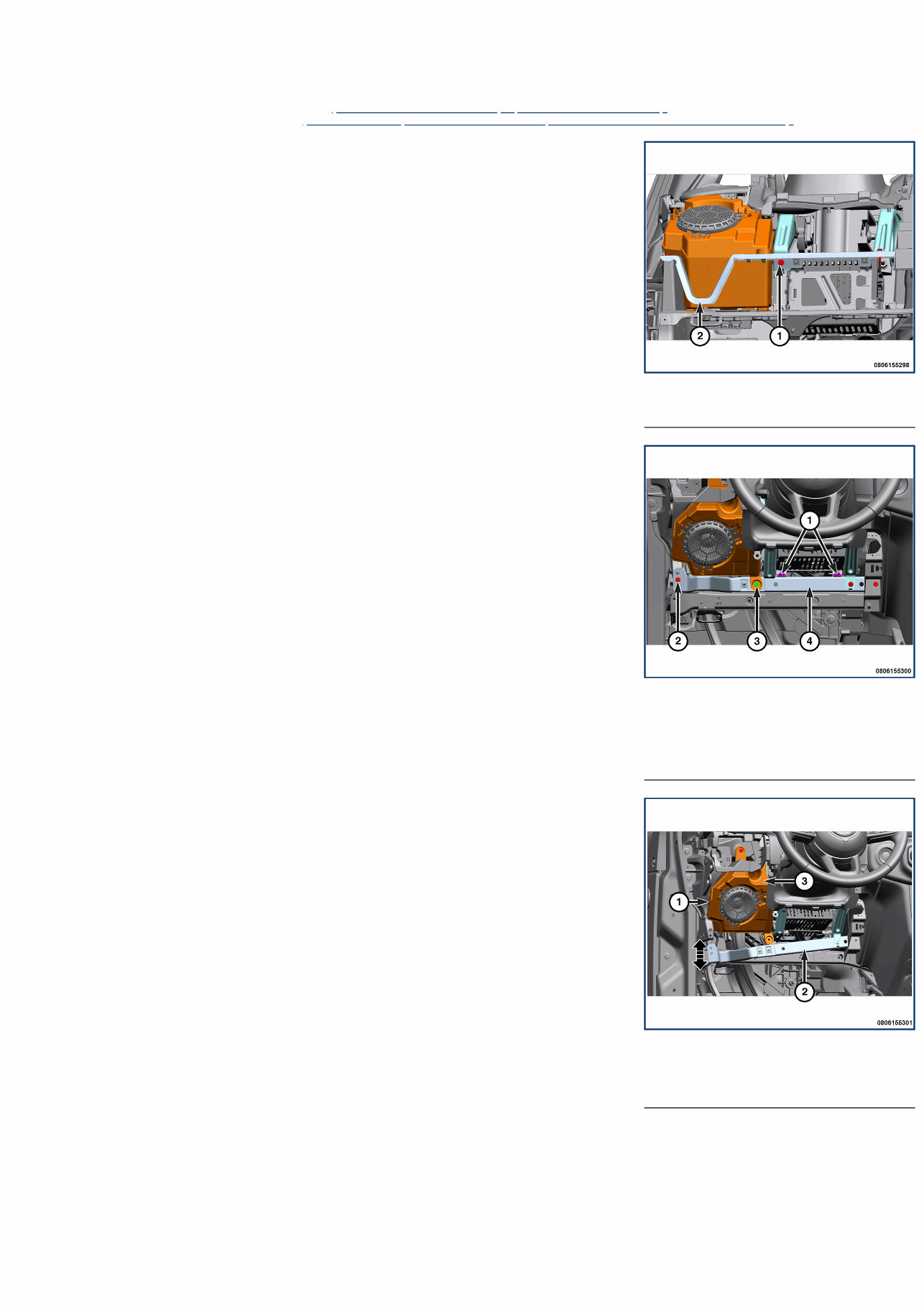
1 - Fastener 2 - I/P Bracket 1 - Fasteners 2 - Fastener 3 - Lower Fastener 4 - I/P Bracket 1 - Fastener 2 - I/P Bracket 3 - Speaker Enclosure 08 - Electrical / 8A - Audio/Video/Entertainment/Connectivity / ENCLOSURE, Speaker / Removal and Installation DRIVER SIDE REMOVAL 1. Disconnect and isolate the negative battery cable(s) (Refer to 08 - Electrical/Battery System/Standard Procedure) . 2. Remove the driver side instrument panel cover (Refer to 23 - Body/Instrument Panel/COVER, Instrument Panel/Removal and Installation) . 3. From the bottom of the driver side of the instrument panel (I/P), remove the fastener that secures the horizontal I/P bracket to the left vertical brace. 4. Remove the fasteners from the power inverter bracket. 5. Remove the lower fastener from the driver side speaker enclosure. 6. Remove the fasteners from the horizontal I/P bracket. 7. Position the horizontal I/P bracket downward to retain enough access for the speaker enclosure removal. 8. Remove the fasteners to release the speaker enclosure. 9. Slide speaker enclosure down and then out from the I/P. 10. Disconnect the two Security Gateway Module (SGW) wire harness connectors and the speaker enclosure wire harness connector. Remove the left speaker enclosure from the vehicle.
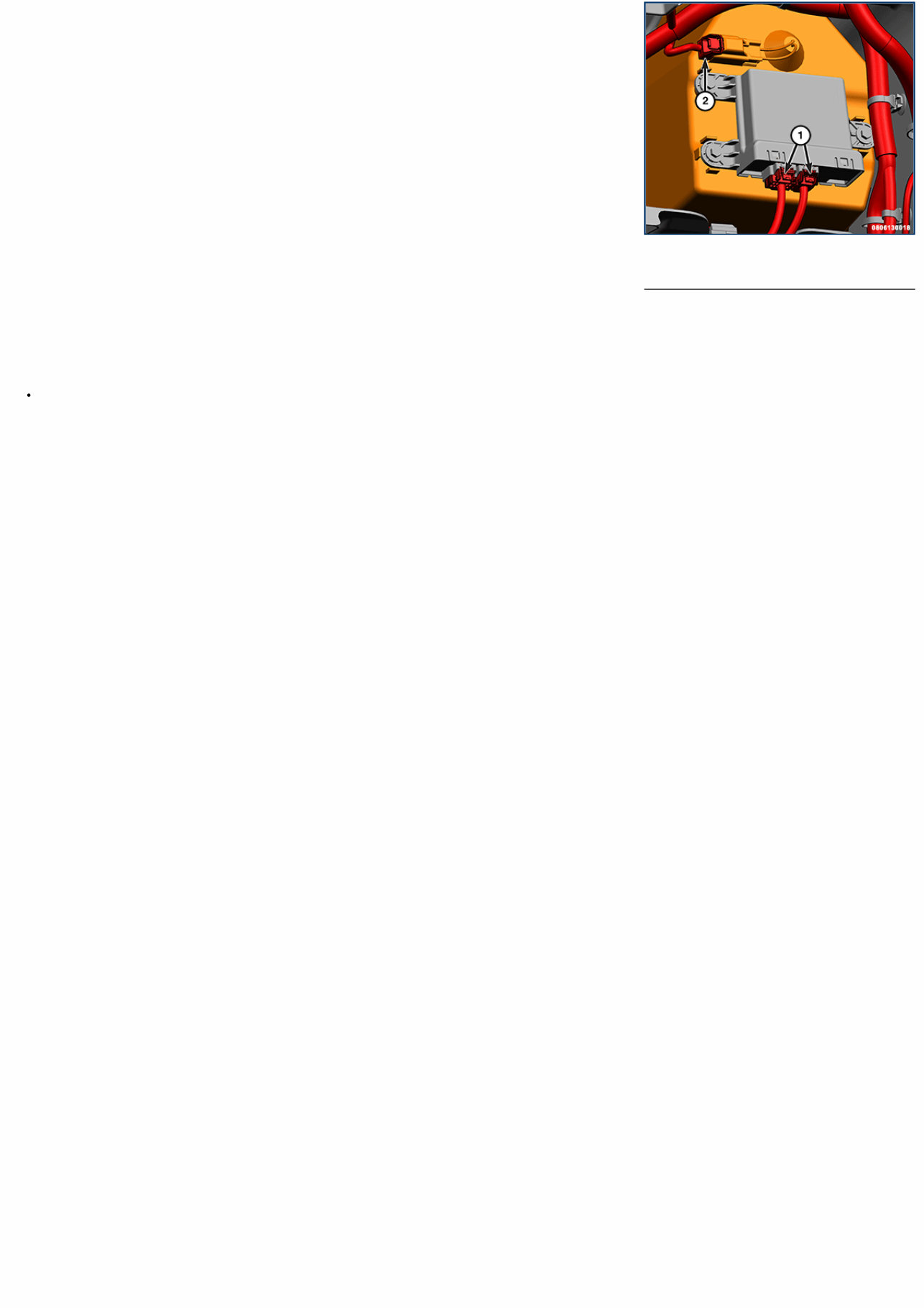
1 - Wire Harness Connectors 2 - Speaker Enclosure Wire Harness Connector INSTALLATION Follow the removal procedure in reverse for general reassembly of the components on the vehicle. The steps listed below are calling out specific procedures that should be followed during installation. Tighten the fasteners securely.
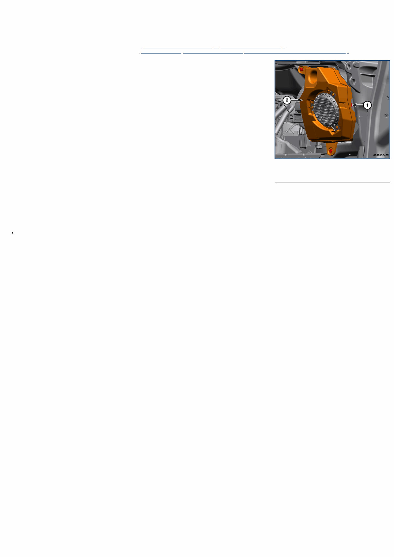
1 - Fastener 2 - Speaker Enclosure 08 - Electrical / 8A - Audio/Video/Entertainment/Connectivity / ENCLOSURE, Speaker / Removal and Installation PASSENGER SIDE REMOVAL 1. Disconnect and isolate the negative battery cable(s) (Refer to 08 - Electrical/Battery System/Standard Procedure) . 2. Remove the passenger side instrument panel cover (Refer to 23 - Body/Instrument Panel/COVER, Instrument Panel/Removal and Installation) . 3. Remove the fasteners. 4. Disconnect the wire harness connector and remove the passenger side speaker enclosure. INSTALLATION Follow the removal procedure in reverse for general reassembly of the components on the vehicle. The steps listed below are calling out specific procedures that should be followed during installation. Tighten the fasteners securely.
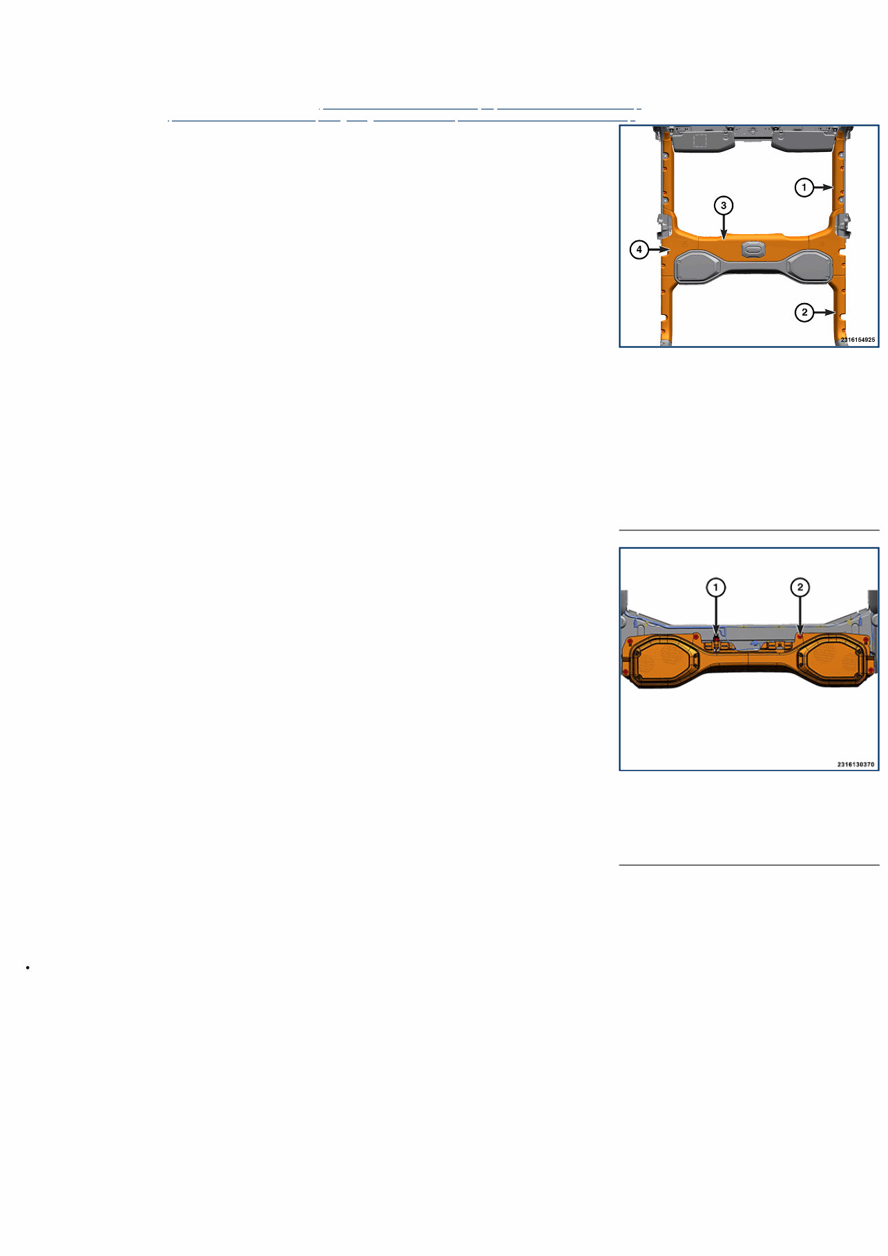
1 - Front Door Sport Bar Cover 2 - Rear Door Sport Bar Cover 3 - Center Sports Bar Cover 4 - Sport Bar Cover 1 - Wire Harness Connector 2 - Bolts 08 - Electrical / 8A - Audio/Video/Entertainment/Connectivity / ENCLOSURE, Speaker / Removal and Installation SPORT BAR - WITHOUT SIDE AIR BAG INFLATABLE CURTAIN REMOVAL 1. Disconnect and isolate the negative battery cable(s) (Refer to 08 - Electrical/Battery System/Standard Procedure) . 2. Remove the dome lamp (Refer to 08 - Electrical/Lamps/Lighting - Interior/LAMP, Dome/Removal and Installation) . 3. Remove the screws from the driver and passenger side front door sport bar covers. Remove both trim covers from vehicle. 4. Remove the screws from the driver and passenger side rear door sport bar covers. Remove both trim covers from vehicle. 5. Remove the screws from the center sport bar cover. Remove center sport bar cover from vehicle. 6. Remove the wire harness fasteners. 7. Remove the screw and plastic fastener from the driver and passenger side sport bar cover. Using a trim stick of equivalent, remove both trim covers from vehicle. 8. Disconnect the wire harness connector, remove the bolts and lower the sport bar speaker enclosure. INSTALLATION Follow the removal procedure in reverse for general reassembly of the components on the vehicle. The steps listed below are calling out specific procedures that should be followed during installation. All fasteners are tightened securely.
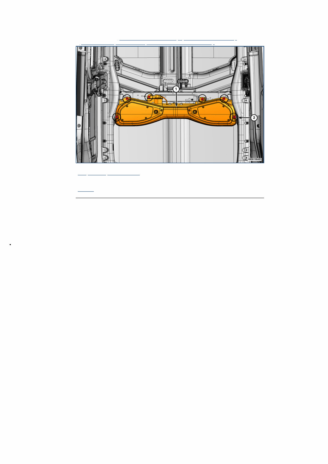
08 - Electrical / 8A - Audio/Video/Entertainment/Connectivity / ENCLOSURE, Speaker / Removal and Installation SPORT BAR - WITH SIDE AIR BAG INFLATABLE CURTAIN REMOVAL 1. Disconnect and isolate the negative battery cable(s) (Refer to 08 - Electrical/Battery System/Standard Procedure) . 2. Remove the center header panel (Refer to 23 - Body/Interior/PANEL, Header/Removal and Installation) . 1 - Sport Bar Speaker Enclosure 2 - Bolts 3. Disconnect the wire harness connector, remove the bolts and lower the sport bar speaker enclosure. INSTALLATION Follow the removal procedure in reverse for general reassembly of the components on the vehicle. The steps listed below are calling out specific procedures that should be followed during installation. Bolts are tightened securely.
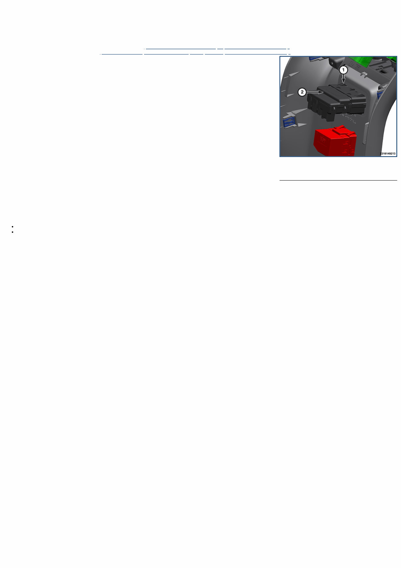
1 - Tab 2 - Media Hub 08 - Electrical / 8A - Audio/Video/Entertainment/Connectivity / MEDIA HUB / Removal and Installation FLOOR CONSOLE MEDIA HUB REMOVAL 1. Disconnect and isolate the negative battery cable(s) (Refer to 08 - Electrical/Battery System/Standard Procedure) . 2. Remove the floor console end cap (Refer to 23 - Body/Interior/CONSOLE, Floor, End Cap/Removal and Installation) . 3. Working inside the floor console end cap, using a trim tool or equivalent, release the two tabs on the floor console media hub, then remove the media hub from the floor console end cap. INSTALLATION Follow the removal procedure in reverse for general reassembly of the components on the vehicle. The steps listed below are calling out specific procedures that should be followed during installation. Line up the floor console media hub with the opening in the floor console end cap. Push the floor console media hub into the opening in the floor console end cap until both retaining tabs are securely engaged with the floor console end cap.
Keep Your 2020 Jeep Wrangler Running Smoothly And Efficiently With The Help Of This Comprehensive Service And Repair Manual. No Longer Do You Have To Rely On Expensive Trips To The Mechanic For Every Little Issue - This Manual Provides You With Everything You Need To Diagnose And Fix Problems On Your Own.
With Step-By-Step Instructions, Clear Images, And Exploded-View Illustrations, You'Ll Have All The Information You Need To Troubleshoot And Replace Any Part On Your Vehicle. Regular Maintenance Is Essential For Keeping Your Jeep In Top Shape, And This Manual Makes It Easy To Stay On Top Of It.
Featuring The Manufacturer'S Recommended Troubleshooting Charts And Replacement Procedures, This Repair Manual Is An Invaluable Resource For Any Jeep Wrangler Owner. Say Goodbye To Flipping Through Hundreds Of Pages Or Struggling With Greasy, Torn, Or Lost Pages - This Electronic Manual Is User-Friendly And Easy To Navigate.
Compatible With A Wide Range Of Electronic Devices, Including Pc And Mac Computers, Android And Apple Smartphones And Tablets, This Manual Is Always At Your Fingertips. No Matter Where You Are, You'Ll Have Access To The Information You Need To Keep Your Jeep Running Smoothly.
And If You Prefer A Physical Copy, You Can Easily Print Out The Manual For Easy Reference. Don'T Wait Until A Small Issue Turns Into A Costly Repair - Get Your Hands On The 2020 Jeep Wrangler Service And Repair Manual And Take Control Of Your Vehicle'S Maintenance Today.
Recently Viewed
5,521,897Happy Clients
2,594,462eManuals
1,120,453Trusted Sellers
15Years in Business
Price:
Actual Price:
2020 Jeep Wrangler 2.0L I4 DOHC Di Turbo W-ESS Service & Repair Manual