WAR DEPARTMENT TECHNICAL MANUAL ORDNANCE MAINTENANCE Power Train, Body, and Frame for l/4-Ton 4x4 Truck (Willys-Overland Model MB and Ford Model GPW) Digital Reprint CHQSOFTWARE.COM WAR DEPARTMENT l APRIL 1944
TM 9-1803B 1 ORDNANCE MAINTENANCE -POWER TRAIN, BODY, AND FRAME FOR %-TON 4 x 4 TRUCK (WILLYS-OVERLAND MODEL MB AND FORD MODEL GPW) CHAPTER 1 INTRODUCTION 1. SCOPE. a. The instructions contained in this manual are for the informa- tion and guidance of personnel charged with the maintenance and repair of the power train, body, and frame of the %-ton 4x4 truck. These instructions are supplementary to field and technical manuals prepared for the using arms. This manual does not contain informa- tion which is intended primarily for the using arms, since such infor- mation is available to ordnance maintenance personnel in loo-series TM’s or FM’s. b. This manual contains a description of, and procedure for, re- moval, disassembly, inspection, and repair of the transmission, trans- fer case, axles, body, and frame. c. TM 9-803 contains operating instructions and information for the using arms. d. TM 9-1803A contains instructions for the information and guidance of personnel charged with the maintenance and repair of the 4-cylinder engine used in these vehicles. e. TM 9-1825B contains information for the maintenance of the Auto-Lite electrical equipment. f. TM g-182619 contains information for the maintenance of the Carter carburetor. g. TM 9-1827C contains information for the maintenance of the Wagner hydraulic brake system. b. TM 9-1828A contains information for the maintenance of the A. C. fuel pump. i. TM 9-1829A contains information for the maintenance of the speedometer. j- This manual includes pertinent ordnance maintenance instruc- tions from the following Quartermaster Corps IO-series Technical Manuals. Together with TM 9-803 and TM 9-1803A, this manual supersedes them : (1) TM 10-1103, dated 20 August 1941. (2) TM 10-1207, dated 20 August 1941. (3) TM 10-1349, dated 3 January 1942. (4) TM 10-1513, Changes 1, dated 15 January 1943. 4
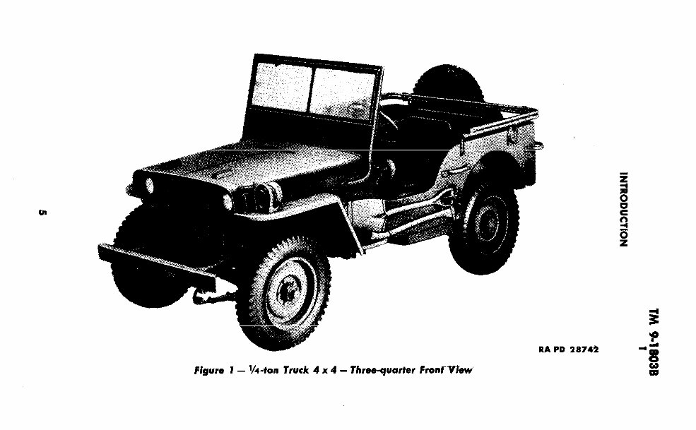
Figure 1 - Vi-ton Truck 4 x 4 - Threequarter Fronfttfew RA PD 28742
TM 9;1803B ORDNANCE MAINTENANCE -POWER TRAIN, BODY, AND FRAME FOR %.lOll 4 x 4 TRUCK (WlllYMYERlAMD MODEL MB AND FORD MODEL 6PW) 2. MWO AND MAJOR UNIT ASSEMBLY REPLACEMENT RECORD. a. Description. Every vehicle is supplied with a copy of AGO Form No. 478 which provides a means of keeping a record of MWO’s completed or major unit assemblies replaced. This form includes spaces for the vehicle name and U. S. A. Registration Number, in- structions for use, and information pertinent to the work accom- plished. It is very important that this form be used as directed and that it remain with the vehicle until the vehicle is removed from service. b. _Instructions for Use. Personnel performing modifications or major unit assembly replacements must record clearly on the form, a description of the work completed, and must initial the form in the columns provided. When each modification is completed, record the date, hours and/or mileage, and MWO number. When major unit assemblies, such as engine, transmission, transfer case, are re- placed, record the date, hours and/or mileage and nomenclature of the unit assembly. Minor repairs and minor parts and accessory replacements need not be recorded. c. Early Modifications. Upon receipt of a vehicle for modifica- tion or repair, by a third or fourth echelon repair facility, mainte- nance personnel will record the MWO numbers of modifications applied prior to the date of AGO Form No. 478. 6
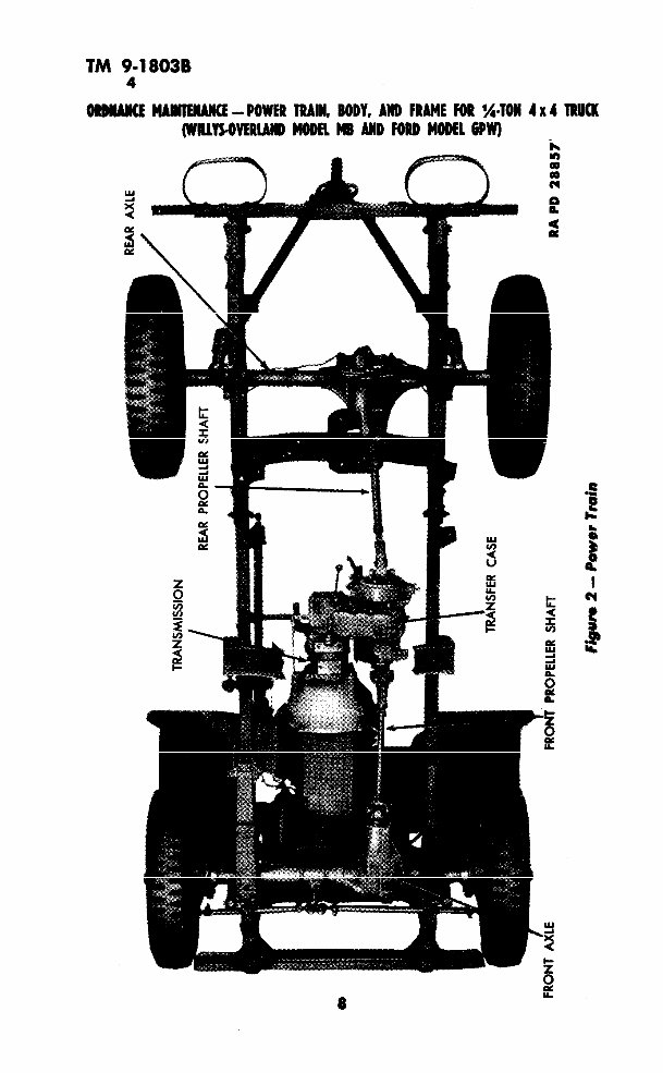
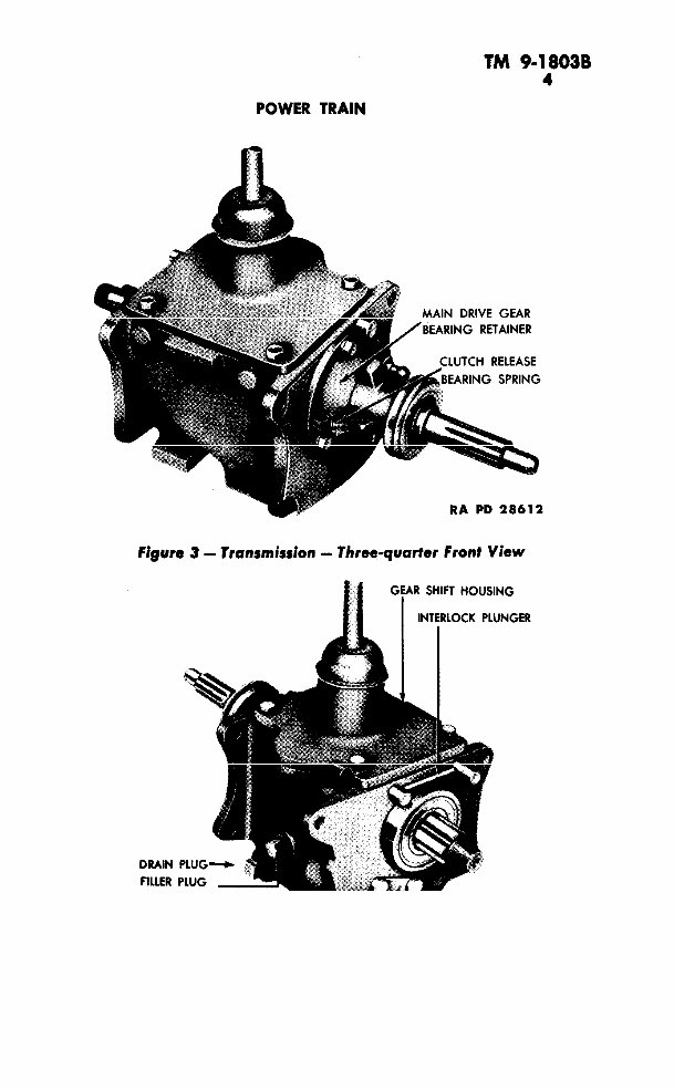
CHAPTER 2 POWER TRAIN Section I POWER TRAIN DESCRIPTION 3. POWER TRAIN DESCRIPTION. a. The power from the engine is transmitted to the driving wheels through a transmission and a transfer case, each of which provides a means of selecting the gear reduction. The power from the trans- fer case is transmitted to the front and rear axles through propeller shafts equipped with universal joints. The transmission is located at the rear of the engine and is secured to the clutch housing (fig. 2 ). The various gears in the transmission (par. 4) are controlled by a shift lever. The transfer case is mounted directly onto the rear of the transmission. The transmission output shaft extends from the rear of the transmission into splines of the main drive gear in the transfer case. The transfer case is provided with two levers, one to select the transfer case ratio, and the other to engage or disengage the front axle (fig. 5). A hand brake drum is mounted on the rear axle output shaft Each axle is of the spiral bevel hypoid gear full- floating type, equipped with the conventional differential. Section II TRANSMISSION 4. DESCRIPTION AND DATA. a. Deecription. The transmission (fig. 3) is of the %-speed type with synchronized second and high speed gears. The transmission and transfer case are mounted on rubber on the frame center cross-’ member. The gearshift lever is incorporated in the gearshift housing. b. Data. Make .. ... ... . .. .... .. ... ... ... .... . .. ... . . . .. .... .. .... . .. ... ... . .. .. . .,. Warner Model ... ... ... .. .... ...... ... ..... ... .. ... .... ..... ... .... .... ... ... .. .. .... ... .... ... .... .... ... T84J Type ... ... ... .. ... ... ,.. , .. . .. .. ..... ... ... .... ... .. ... . .... .. ... .. Synchronous Mesh speeds: Forward . ... .. ... ... .,.. .... ... . . ... .. ... ... ..... .. .... ... .. ... ... . . .... ... .... ....., .... ..... 3 Reverse . . . .. . .... ... .... .. .. ... . .. . ... . .. . . ... ... ... . ... . .. .... .... ... . . . .. ... .... 1 Ratios: Low ... .... .... ... ... ... ... ... ... ... ... .. .... .. ... ..... .... .... ... ... .... ..... ... ..... .. 2.665 to 1 Second .. . ... ... ... .... .. ... ... ... .... ... .... ... .. .. ... ... ..... ... ... .... ... .. .. 1.564 to 1 7
TM 9-18038 4 IAW MllERARCE -POWER TRAIN, BODY, AND FRAME FOR %lOR 4 x 4 1 (WMYWERLARD MODEL MB ARD FORD MODEL 6PW) a L
POWER TRAIN TM 9-18038 1 Figure 3 - Transmission - Three-quarter Front View GEAR SHIFT HOUSIN I INTERLOCK PLUNGER I DRAIN FILLER COUNTER SHAFT AND IDLER SHAFT LOCK ‘PlAii IA PD 28607 Figure 4 - Transmission - Three-quarter Rear View 9
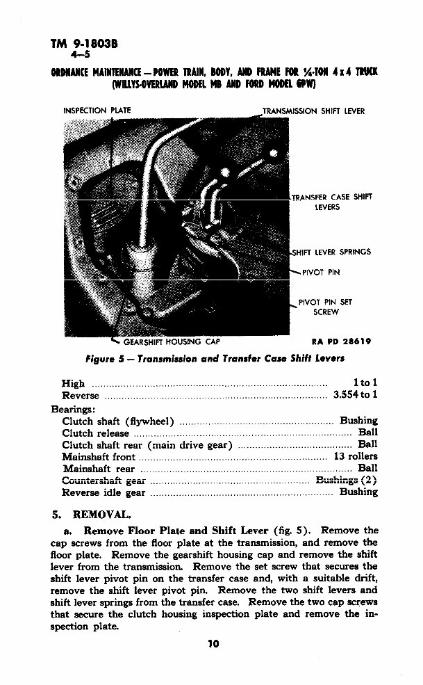
TM 9-18038 4-s ORDRARCE MAWENARCE -POWER TRAIN, BODY, AND FRAME FOR (/,-TON (WILLYWERLARD MODEL MB ARD FORD MODEL 6PW) 4x4 TRUCK INSPECTION PLATE TRANSMISSION SHIFT LEVER iTRANSFER CASE LEVERS iSHIFT LEVER SPR jPlVOT PIN , PIVOT PIN SET SCREW RA PD 28 SHIFT INGS 1619 Figure 5 - Transmission and Transfer Case Shift Levers High . . . . . . . . .. .. . . .. 1to1 Reverse . ..... ...... ... ...._._........................................................ 3.554 to 1 Bearings: Clutch shaft (flywheel) .._, ._.. _.. ...__. ... . ... . .... ... Bushing Clutch release . . . . ... . .. .. Ball Clutch shaft rear (main drive gear) .. .. ... . . . ... . Ball Mainshaft front . . _. . . ... _. _. . .... ... . 13 rollers Mainshaft rear . .. .... .. .._..._.......................................................... Ball Countershaft gear . . . . . . .. . . .. . Bushings (2 ) Reverse idle gear . _. . . . . .,. .. .. .. ... Bushing 5. REMOVAL. a. Remove Floor Plate and Shift Lever (fig. 5). Remove the cap screws from the floor plate at the transmission, and remove the floor plate. Remove the gearshift housing cap and remove the shift lever from the transmission. Remove the set screw that secures the shift lever pivot pin on the transfer case and, with a suitable drift, remove the shift lever pivot pin. Remove the two shift levers and shift lever springs from the transfer case. Remove the two cap screws that secure the clutch housing inspection plate and remove the in- spection plate. 10
This Jeep Willys Maintenance Technical manual is a comprehensive guide for individuals interested in the technical details of this brand. It provides immediate access to all the technical details directly from the manufacturer. Whether you are a professional mechanic or a DIY enthusiast, this manual offers complete information on maintenance and repairs for any Jeep Willys model.
Our team of skilled mechanics has dedicated their know-how to ensure this manual includes quality information, various equipment, and diagrams. It is designed to offer a wide range of solutions, high technical skills, and detailed diagnostics, repair, and maintenance instructions for Jeep Willys vehicles.
Upon accessing this manual, you will find detailed mechanical and technical specifications, introductory mechanics, equipment elevation, collision information, products and supplies, painting details, and descriptions of various vehicle parts. Each section is easily printable for your convenience.
Furthermore, this manual promotes environmental sustainability by providing information without the need for printed books. It emphasizes the advantages of accessing information in the 21st century without the wait or environmental impact associated with traditional printed manuals.
Whether you need step-by-step instructions, access to pictures, diagrams, assembly, disassembly, cleaning, repairing, or maintenance guidance, this manual has you covered. It is a valuable resource for anyone seeking comprehensive information on Jeep Willys Maintenance Technical manual.
Mechanical specifications of the vehicle
Technical specifications of the vehicle
Introductory Mechanics
Equipment elevation
Collisions
Products and supplies
Painting
Description of various parts of the vehicle
Accessing this manual instantly provides you with the opportunity to start your maintenance or repair tasks without delay. Say goodbye to waiting weeks or months for printed manuals and paying postage. With just one click, you can access all the information you need and begin your tasks immediately.