Contents Introductory pages About this manual 0 -5 Introduction to the Jeep Cherokee and Comanche 0 -5 Vehicle identification numbers 0 -7 Buying parts 0 -10 Maintenance techniques, tools and working facilities 0 -10 Booster battery (jump) starting 0 -17 Jacking and towing 0 -17 Automotive chemicals and lubricants 0 -19 Safety first! Q-20 Conversion factors 0-21 Troubleshooting 0 -22 Chapter 1 Tune-up and routine maintenance 1-1 Chapter 2 Part A Four-cylinder engine 24-1 Chapter 2 Part B V6 engine 28-0 Chapter 2 Part C Inline six-cylinder engine 2C-0 Chapter 2 Part D General engine overhaul procedures 2D-0 Chapter 3 Cooling, heating and air conditioning systems Chapter 4 Fuel and exhaust systems 4 -0 Chapter 7 Part A Manual transmlsslon Transfer case Chapter 8 Clutch and drlvetraln Chapter 9 Brakes Chapter 10 Suspension and steer~n systems Chapter 11 Body Chapter 12 Chassls electrical system Wiring diagrams 12-9 Index IMD -1 The Motor Manual Guy
The Motor Manual Guy
The Motor Manual Guy
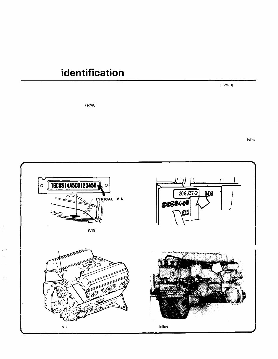
Vehicle identification numbers Modifications are a continuing and unpublicized process in vehicle of production, the Gross Vehicle Weight Rating (GVWR) and the certi- manufacturing. Since spare parts manuals and lists are compiled on fication statement. a numerical basis, the individual vehicle numbers are essential to cor- rectly identify the component required. Vehicle Identification Plate Vehicle ldentification Number (VINI This very important identification number is stamped on a plate at- tached to the left side of the dashboard just inside the windshield on the driver's side of the vehicle (see illustration). The VIN also appears on the Vehicle Certificate of Title and Registration. It contains informa- tion such as where and when the vehicle was manufactured, the model year and the body style. Safety Certification label The Safetv Certification label is affixed to the left front door pillar. This plate is located on the radiator support on the driver's side. It contains information on the vehicle model, emission certification, engine and transmission type as well as the paint code. Engine identification number The engine ID number on four-cylinder engines is located on a ma- chined surface on the right side of the block between the number three and four cylinders (see illustration). On V6 engines, the ID number is located on a pad at the front of the block (see illustration). On inline six-cylinder engines, the ID number is located on a machined surface on the right side of the block between the number two and three The plate contains the name of the manufacturer, the month and year cylinders (see illustration). The Vehicle ldentification Number (VIN) is visible from outside the vehicle through the driver's side of the windshield Four-cylinder engine ID number location V6 engine ID number location Inline six-cylinder engine ID number location The Motor Manual Guy
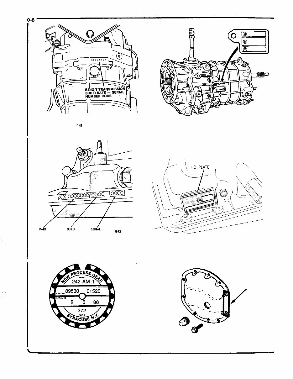
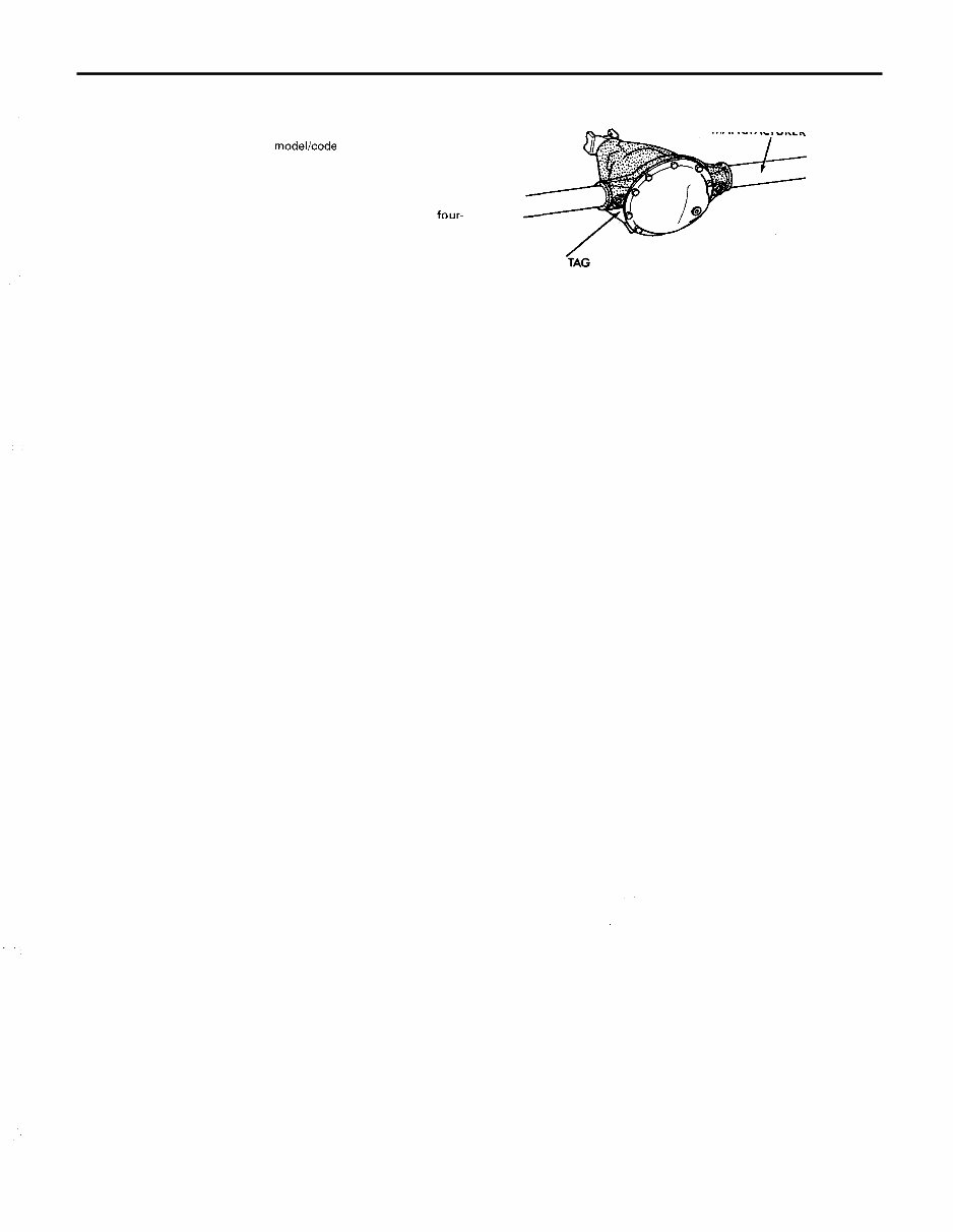
The build date and serial number are stamped on the bottom of the AX 415 manual transmission case PA~ SERIA NUMBER DATE NUMBER 1892 1- 363 The three-speed automatic transmission numbers are stamped on the edge of the left side of the case Typical transfer case ID tag BA 1015 manual transmission ID number location TRANSMISSION n The four-speed automatic transmission ID plate is on the right rear side of the case Front axle ID number location The Motor Manual Guy
Vehicle identification numbers 0-9 Transmission identification number The ID number on T 415 manual transmissions is located on a tag attached to the rear of the case. On AX 415 manual transmissions, there are two identification codes: a modellcode shipping date stamped on the shift tower and an eight digit code stamped on the bottom sur- face of the case (see illustration). On the BA 1015 manual transmission, the ID plate is attached to the left side of the front case (see illustration). On three-speed automatic transmissions the ID numbers are stamped on the left edge of the case (see illustration). The ID plate on four- speed automatic transmissions is located on the right rear of the case (see illustration). Transfer case identification number On most models the transfer case identification plate is located on the left rear side of the case (see illustration). Axle identification numbers On most front axles the identification number is located on a tag attached to the differential housing cover (see illustration). On rear BUILD DATE AND MANUFACTURER I . D . -TAG LOCATION Rear axle number locations NO. axles, the identification tag is on the left side of the housing and the build date and manufacturer number are stamped on the axle tube (see illustration). The Motor Manual Guy
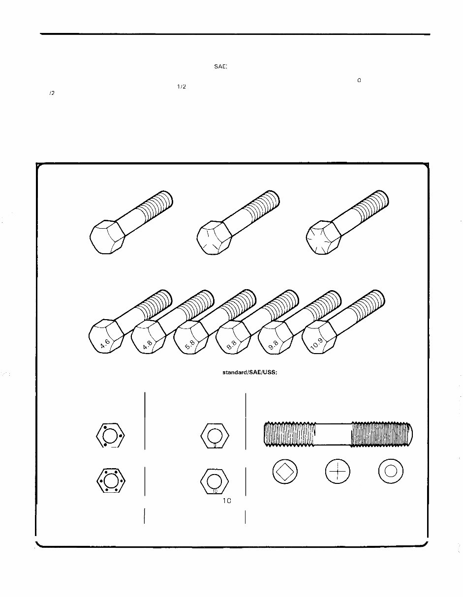
Maintenance techniques, tools and working facilities 0-1 1 Fastener sizes For a number of reasons, automobile manufacturers are making wider and wider use of metric fasteners. Therefore, it is important to be able to tell the difference between standard (sometimes called U.S. or SAEI and metric hardware, since they cannot be interchanged. All bolts, whether standard or metric, are sized according to diameter, thread pitch and length. For example, a standard 112 - 13 x 1 bolt is 1 12 inch in diameter, has 13 threads per inch and is 1 inch long. An M12 - 1.75 x 25 metric bolt is 12 mm in diameter, has a thread pitch of 1.75 mm (the distance between threads) and is 25 mm long. The two bolts are nearly identical, and easily confused, but they are not interchangeable. In addition to the differences in diameter, thread pitch and length, metric and standard bolts can also be distinguished by examining the bolt heads. To begin with, the distance across the flats on a standard bolt head is measured in inches, while the same dimension on a metric bolt is sized in millimeters (the same is true for nuts). As a result, a standard wrench should not be used on a metric bolt and a metric wrench should not be used on a standard bolt. Also, most standard bolts have slashes radiating out from the center of the head to denote the grade or strength of the bolt, which is an indication of the amount of torque that can be applied to it. The greater the number of slashes, the greater the strength of the bolt. Grades 0 through 5 are commonly used on automobiles. Metric bolts have a property class (grade) number, rather than a slash, molded into their heads to indicate bolt strength. In this case, the higher the number, the stronger the bolt. Property class numbers 8.8, 9.8 and. 10.9 are commonly used on automobiles. Strength markings can also be used to distinguish standard hex nuts from metric hex nuts. Many standard nuts have dots stamped into one side, while metric nuts are marked with a number. The greater the number of dots, or the higher the number, the greater the strength of the nut. Metric studs are also marked on their ends according to property class (grade). Larger studs are numbered (the same as metric bolts), Grade Hex Nut Grade 5 Hex Nut Grade 8 Grade 1 or 2 Grade 5 Grade 8 Bolt strength markings (top - standardlSAE1USS; bottom - metric) Hex Nut Property Class 9 Identification 3 Dots I Arabic 9 I Class Identification Hex Nut Property Class 1 0 6 Dots I Arabic I 0 I Standard hex nut strength I Metric hex nut strength markings markings I CLASS CLASS CLASS 10.9 9.8 8.8 Metric stud strength markings The Motor Manual Guy
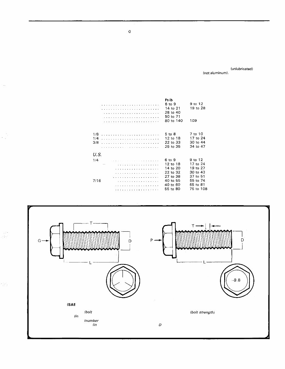
0-1 2 Maintenance techniques, tools and working facilities while smaller studs carry a geometric code to denote grade. It should be noted that many fasteners, especially Grades 0 through 2, have no distinguishing marks on them. When such is the case, the only way to determine whether it is standard or metric is to measure the thread pitch or compare it to a known fastener of the same size. Standard fasteners are often referred to as SAE, as opposed to metric. However, it should be noted that SAE technically refers to a non-metric fine thread fastener only. Coarse thread non-metric fasteners are referred to as USS sizes. Since fasteners of the same size (both standard and metric) may have different strength ratings, be sure to reinstall any bolts, studs or nuts removed from your vehicle in their original locations. Also, when re- placing a fastener with a new one, make sure that the new one has a strength rating equal to or greater than the original. Tightening sequences and procedures Most threaded fasteners should be tightened to a specific torque value (torque is the twisting force applied to a threaded component such as a nut or bolt). Overtightening the fastener can weaken it and cause it to break, while undertightening can cause it to eventually come loose. Bolts, screws and studs, depending on the material they are made of and their thread diameters, have specific torque values, many of which are noted in the Specifications at the beginning of each Chapter. Be sure to follow the torque recommendations closely. For fasteners not assigned a specific torque, a general torque value chart is presented here as a guide. These torque values are for dry (unlubricated) fasteners threaded into steel or cast iron hot aluminum). As was previously men- tioned, the size and grade of a fastener determine the amount of torque that can safely be applied to it. The figures listed here are approximate Metric thread sizes M-6 ......................... M-8 ........................ M-10 ....................... M-12 ........................ M-14 ........................ Pipe thread sizes 118 ........................ 114 ........................ 318 ......................... 1/2 ........................ U. S. thread sizes 114 - 20 .................... 5/16 - 18.. .................. 5116 - 24. .................. 318 - 16.. ................... 318 - 24. .................... 7/16 - 14.. .................. 7/16 - 20. ................... 112 - 13.. ................... Nmlm 9t0 12 lgto 28 38 to 54 68 to 96 109 to 154 Standard (SAE and USS) bolt dimensionslgrade marks G Grade marks lbolt strength) L Length (in inches) T Thread pitch (number of threads per inch) D Nominal diameter (in inches) dl f-l I- Metric bolt dimensionslgrade marks P Property class lbolt strength) L Length (in millimeters) T Thread pitch (distance between threads in millimeters) D Diameter The Motor Manual Guy
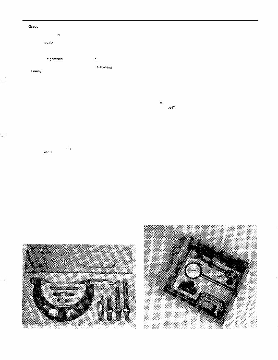
Maintenance techniques, tools and working facilities 0 -13 for Grade 2 and Grade 3 fasteners. Higher grades can tolerate higher torque values. Fasteners laid out In a pattern, such as cylinder head bolts, oil pan bolts, differential cover bolts, etc., must be loosened or tightened in sequence to avo~ warping the component. This sequence will nor - mally be shown in the appropriate Chapter. If a specific pattern is not given, the following procedures can be used to prevent warping. Initially, the bolts or nuts should be assembled finger-tight only. Next, they should be t~ghtene one full turn each, In a criss-cross or diagonal pattern. After each one has been tightened one full turn, return to the first one and tighten them all one-half turn, followmg the same pat - tern. Fmally, tighten each of them one-quarter turn at a time until each fastener has been tightened to the proper torque. To loosen and remove the fasteners, the procedure would be reversed. Component disassembly Component disassembly should be done with care and purpose to help ensure that the parts go back together properly. Always keep track of the sequence in which parts are removed. Make note of special characteristics or marks on parts that can be installed more than one way, such as a grooved thrust washer on a shaft. It is a good idea to lay the disassembled parts out on a clean surface in the order that they were removed. It may also be helpful to make sketches or take instant photos of components before removal. When removing fasteners from a component, keep track of their loca- tions. Sometimes threading a bolt back in a part, or putting the washers and nut back on a stud, can prevent mix- ups later. If nuts and bolts cannot be returned to their original locations, they should be kept in a compartmented box or a series of small boxes. A cupcake or muffin tin is ideal for this purpose, since each cavity can hold the bolts and nuts from a particular area (i.e. oil pan bolts, valve cover bolts, engine mount bolts, etc.). A pan of this type is especially helpful when work - ing on assemblies with very small parts, such as the carburetor, alter- nator, valve train or interior dash and trim pieces. The cavities can be marked with paint or tape to identify the contents. Whenever wiring looms, harnesses or connectors are separated, it is a good idea to identify the two halves with numbered pieces of mask- ing tape so they can be easily reconnected. Gasket sealing surfaces Throughout any vehicle, gaskets are used to seal the mating sur- faces between two parts and keep lubricants, fluids, vacuum or pressure contained in an assembly. Many times these gaskets are coated with a liquid or paste- type gasket sealing compound before assembly. Age, heat and pressure can sometimes cause the two parts to stick together so tightly that they are very difficult to separate. Often, the assembly can be loosened by striking it with a soft - face hammer near the mating surfaces. A regular hammer can be used if a block of wood is placed between the hammer and the part. Do not hammer on cast parts or parts that could be easily damaged. With any particularly stubborn part, always recheck to make sure that every fastener has been removed. Avoid using a screwdriver or bar to pry apart an assembly, as they can easily mar the gasket sealing surfaces of the parts, which must remain smooth. If prying is absolutely necessary, use an old broom handle, but keep in mind that extra clean up will be necessary if the wood splinters. After the parts are separated, the old gasket must be carefully scraped off and the gasket surfaces cleaned. Stubborn gasket material can be soaked with rust penetrant or treated with a special chemical to soften it so it can be easily scraped off. A scraper can be fashioned from a piece of copper tubing by flattening and sharpening one end. Copper is recommended because it is usually softer than the surfaces to be scraped, which reduces the chance of gouging the part. Some gaskets can be removed with a wire brush, but regardless of the method used, the mating surfaces must be left clean and smooth. If for some reason the gasket surface is gouged, then a gasket sealer thick enough to fill scratches will have to be used during reassembly of the com- ponents. For most applications, a non- drying (or semi - drying) gasket sealer should be used. Hose removal tips Warning: If the vehicle is equipped with air conditioning, do not discon- nect any of the A/C hoses without first having the system depressurized by a dealer service department or an air conditioning specialist, Hose removal precautions closely parallel gasket removal precau- tions. Avoid scratching or gouging the surface that the hose mates against or the connection may leak. This is especially true for radiator hoses. Because of various chemical reactions, the rubber in hoses can bond itself to the metal spigot that the hose fits over. To remove a hose, first loosen the hose clamps that secure it to the spigot. Then, with slip- joint pliers, grab the hose at rhe clamp and rotate it around the spigot. Work it back and forth until it is completely free, then pull it off. Silicone or other lubricants will ease removal if they can be applied between the hose and the outside of the spigot. Apply the same lubricant to the inside of the hose and the outside of the spigot to simplify installation. As a last resort (and if the hose is to be replaced with a new one anyway), the rubber can be slit with a knife and the hose peeled from the spigot. If this must be done, be careful that the metal connection is not damaged. If a hose clamp is broken or damaged, do not reuse it. Wire- type clamps usually weaken with age, so it is a good idea to replace them with screw- type clamps whenever a hose is removed. Tools A selection of good tools is a basic requirement for anyone who plans to maintain and repair his or her own vehicle. For the owner who has few tools, the initial investment might seem high, but when compared to the spiraling costs of professional auto maintenance and repair, it is a wise one. Micrometer set Dial indicator set - The Motor Manual Guy
0-1 4 Maintenance techniques, tools and working facilities Dial caliper Hand-operated vacuum pump Timing light Compression gauge with spark plug hole adapter Hydraulic lifter removal tool Ridge reamer Damperlsteering wheel puller General purpose puller Valve spring compressor Valve spring compressor Piston ring groove cleaning tool Ring removallinstallation tool The Motor Manual Guy
The 1990 Jeep Wagoneer OEM Service & Repair Manual is an essential resource for both professional mechanics and DIY enthusiasts. With over 10,000 pages, this comprehensive guide covers:
Engine overhaul and rebuilding
Brake system diagnostics and repair
Sunroof operation and troubleshooting
Timing belt replacement procedures
Trouble code interpretation
Wiring diagrams and electrical troubleshooting
Performance tuning and engine diagnostics
Front end procedures and suspension repair
Transmission troubleshooting and service information
Air conditioning system maintenance
Computer diagnostic codes and firing orders
Factory maintenance schedules
Serpentine and timing belt routings
Complete torque specifications
U-joint and CV-joint service procedures
Hundreds of detailed illustrations
These manuals are compatible with all computers, including PC and Mac, and are available in PDF format for easy access. They allow users to zoom in for detailed parts viewing and print necessary pages, ensuring that no detail is missed. The manual works seamlessly with all Windows and Mac operating systems to provide convenience and clarity.
Whether you prefer to perform repairs independently or require professional guidance, the 1990 Jeep Wagoneer OEM Service & Repair Manual delivers comprehensive coverage and detailed specifications to support your repair needs. Secure payment options, including PayPal and credit card, are available for your convenience.