FOREWORD The information contained in this service manual has been prepared for the professional automotive technician involved in daily repair operations. This manual does not cover theory of operation, which is addressed in service training material. Tightening torques are provided as a specific value throughout this manual. This value represents the midpoint of the acceptable engineering torque range for a given fastener application. These torque values are intended for use in service assembly and installation procedures using the correct OEM fasteners. When replacing fasteners, always use the same type (part number) fastener as removed. Information in this manual is divided into groups. These groups contain general information, diagnosis, testing, adjustments, removal, installation, disassembly, and assembly procedures for the components. The Component and System Index of this manual identifies the correct group for the component or system to be serviced. In addition, a Service Manual Comment form is included at the rear of this manual. Use the form to provide Chrysler Corporation with your comments and suggestions. To assist in locating a group title page, use the Group Tab Locator on the following page. The solid bar after the group title is aligned to a solid tab on the first page of each group. The first page of the group has a contents section that lists major topics within the group. Chrysler Corporation reserves the right to change testing procedures, specifications, diagnosis, repair methods, or vehicle wiring at any time without prior notice or incurring obligation. Information describing the operation and use of standard and optional equipment is included in the Owner’s Manual provided with the vehicle. NOTE: The acronyms, terminology and nomenclature used to identify emissions related components in this manual may have changed from prior publications. These new terms are in compliance with S.A.E. recommended practice J1930. This terminology standard (J1930) is required to comply with the 1993 California Air Research Board (CARB) requirements. NEXT PAGE '
NOTE: Groups with the suffix “-S” are supplements to the original service manual publication. GROUP TAB LOCATOR PAGE IN Introduction 0 Lubrication and Maintenance 2 Front Suspension and Axle 3 Rear Suspension and Axles 5 Brakes 6 Clutch 7 Cooling System 8 Electrical 9 Engines 11 Exhaust System and Intake Manifold 13 Frame and Bumpers 14 Fuel System 16 Propeller Shafts 19 Steering 21 Transmissions and Transfer Cases 21-S Transmissions and Transfer Cases 22 Wheels and Tires 23 Body Components 24 Heating and Air Conditioning 25 Emission Control Systems Index Index Supplement Service Manual Comment Forms (Rear of Manual)
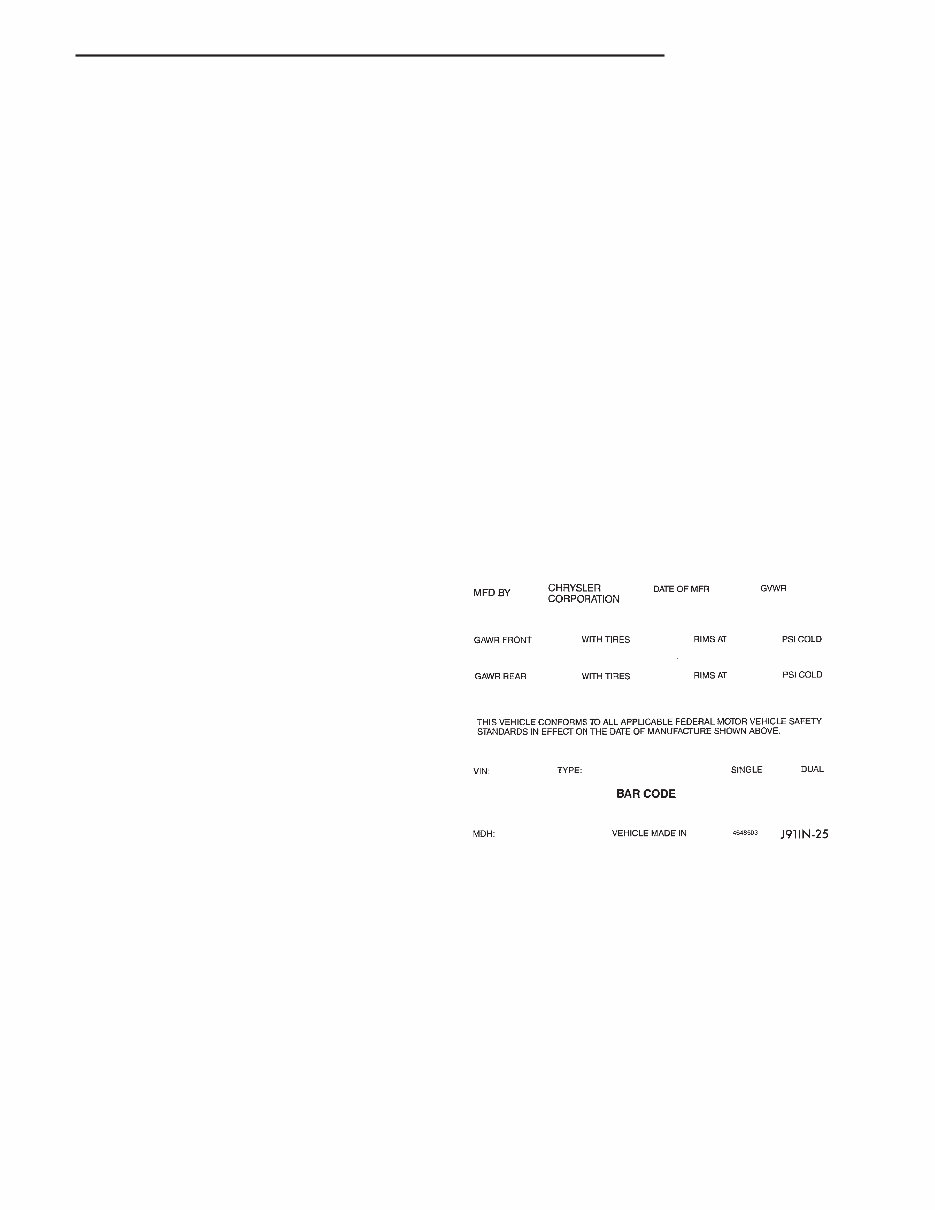
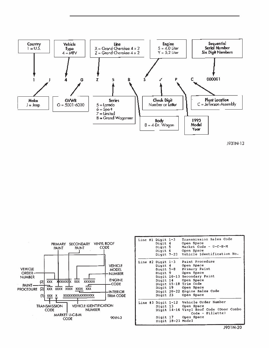
INTRODUCTION CONTENTS page page DESIGNATIONS, LABELS/PLATES/DECALS, CODES AND DIMENSIONS/WEIGHTS ....... 1 MEASUREMENT AND TORQUE SPECIFICATIONS ....................... 5 DESIGNATIONS, LABELS/PLATES/DECALS, CODES AND DIMENSIONS/WEIGHTS INDEX page page Body Code Plate .......................... 1 Engine and Transmission/Transfer Case Identification ............................ 2 International Vehicle Control and Display Symbols .4 Major Component Identification ............... 2 Trailer Towing Specifications .................. 4 Vehicle Designation ........................ 1 Vehicle Dimension ......................... 3 Vehicle Identification Number (VIN) Plate ........ 1 Vehicle Safety Certification Label .............. 1 Vehicle Weights ........................... 3 VEHICLE DESIGNATION The Vehicle Code Designation for Grand Cherokee vehicles is ZJ. The code is used to identify the vehicle in charts, captions and in service procedures. The vehicle code is different than the Vehicle Identifica- tion Number (VIN) or the wheelbase/model code. VEHICLE SAFETY CERTIFICATION LABEL A certification label is attached to the left side B-pillar (Fig. 1). The label certifies that the vehicle conforms to Federal Motor Vehicle Safety Standards (FMVSS).The label also lists the: • Month and year of vehicle manufacture • Gross Vehicle Weight Rating (GVWR). The gross front and rear axle weight ratings (GAWR’s) are based on a minimum rim size and maximum cold tire inflation pressure • Vehicle Identification Number (VIN) • Type of vehicle • Type of rear wheels • Bar code • Month, Day and Hour (MDH) of final assembly VEHICLE IDENTIFICATION NUMBER (VIN) PLATE The Vehicle Identification Number (VIN) plate is attached to the top left side of the instrument panel. The VIN contains 17 characters that provide data concerning the vehicle. Refer to the decoding chart to determine the identification of a vehicle. The Vehicle Identification Number is also imprinted on the: • Body Code Plate • Equipment Identification Plate • Vehicle Safety Certification Label • Frame rail BODY CODE PLATE A metal Body Code plate is attached (riveted) to the top, left side of the radiator reinforcement. There can be a maximum of seven rows of vehicle information imprinted on the plate. The information should be read from left to right, starting with line 1 at the bottom of the plate up to line 7 (as applicable) at the top of the code plate (Fig.2). Refer to the decoding chart to decode lines 1 through 3. Fig. 1 Vehicle Safety Certification Label Z INTRODUCTION 1
Lines 4 through 7 on the plate are imprinted in sequence according to the following descriptions: • 3-character sales code • 3-digit numerical code • 6-digit SEC code If there is not enough space left in the row for all of the 6-digit SEC code: • The unused space will remain blank • The code will be listed in the next row. The last nine positions of row 7 will contain a 2-digit code and a 6-digit serial number. The last code on a body code plate will be followed by the imprinted word END. When two plates are required, the last available spaces on the first plate will be imprinted with the letters CTD (for contin- ued). When a second body code plate is necessary, the first four spaces on each row will not be used because of the plate overlap. ENGINE AND TRANSMISSION/TRANSFER CASE IDENTIFICATION Refer to Group 9—Engines for all engine identifica- tion data. Refer to Group 21—Transmissions for all transmission/transfer case identification data. MAJOR COMPONENT IDENTIFICATION Refer to the applicable group for identification data. VEHICLE IDENTIFICATION NUMBER (VIN) DECODING Fig. 2 Body Code Plate BODY CODE DECODING 2 INTRODUCTION Z
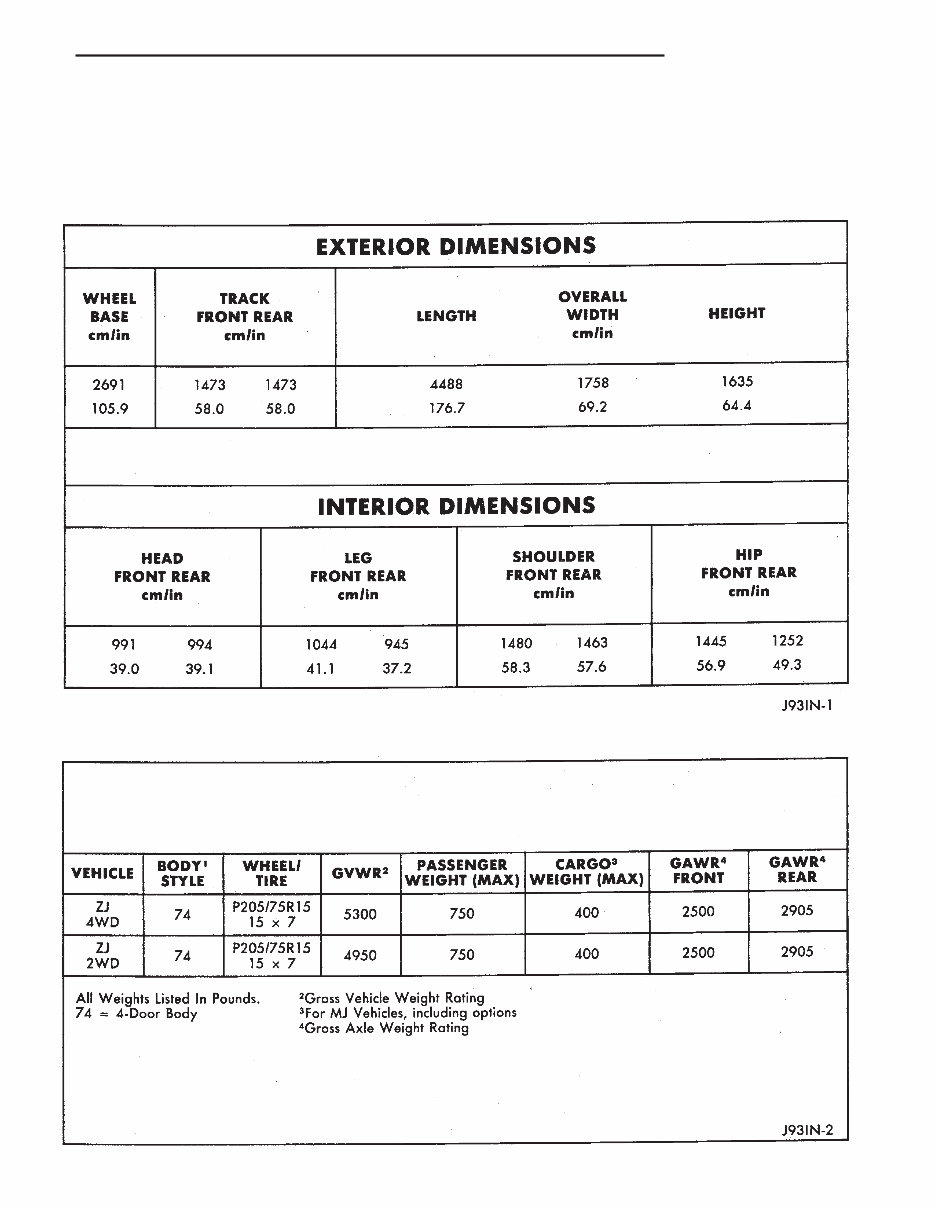
VEHICLE DIMENSION The Vehicle Dimension chart provides the dimen- sions for each type of Grand Cherokee vehicle. VEHICLE WEIGHTS The Vehicle Weights chart provides: • The Gross Vehicle Weight Rating (GVWR), • The payload • The curb weight for each vehicle type/wheelbase VEHICLE DIMENSIONS VEHICLE WEIGHTS Z INTRODUCTION 3
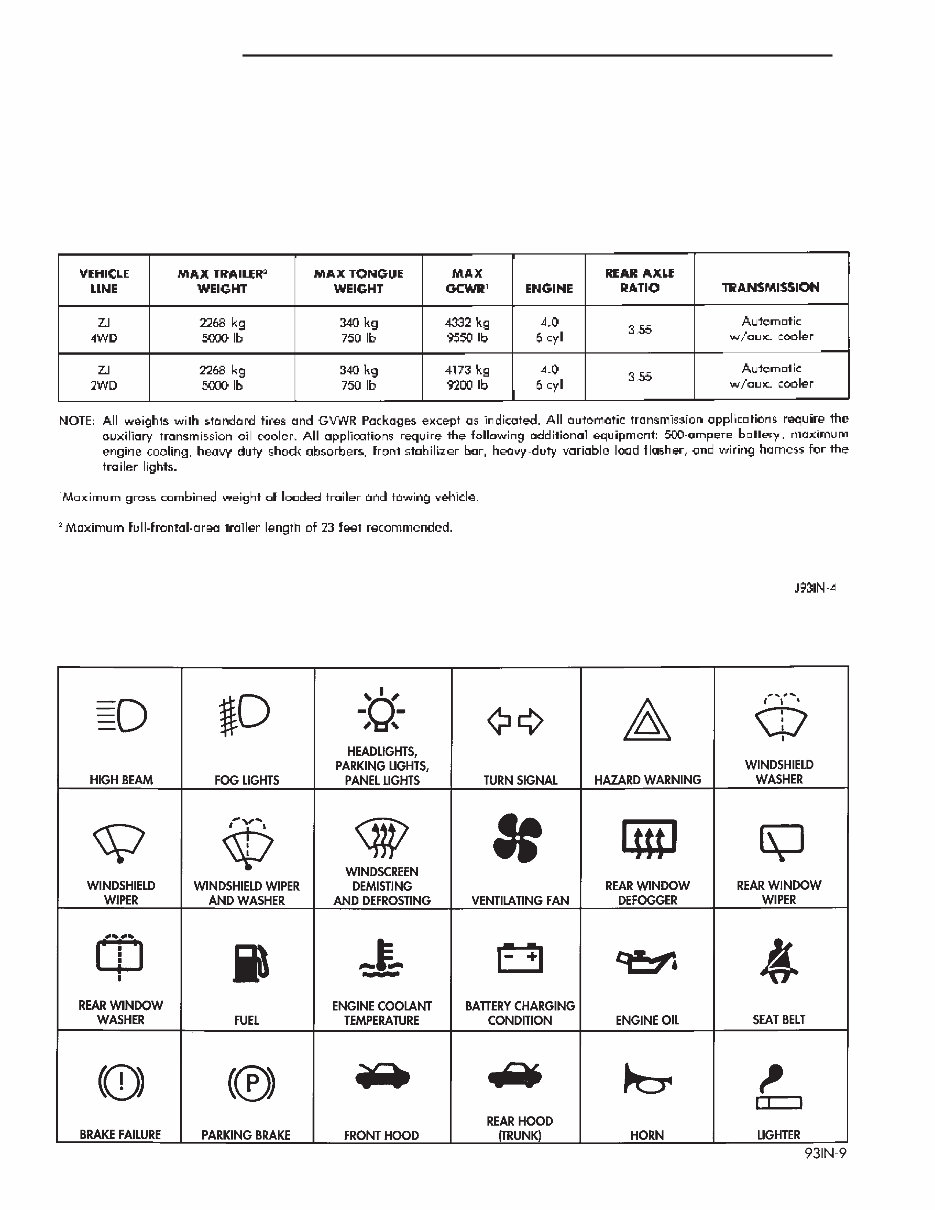
TRAILER TOWING SPECIFICATIONS The Trailer Towing Specifications chart provides: • The maximum trailer tongue weight • The maximum trailer weight • The maximum combined weight of the trailer/load/towing vehicle with a specific engine/transmission/axle combination. INTERNATIONAL VEHICLE CONTROL AND DISPLAY SYMBOLS The graphic symbols illustrated in the following chart are used to identify various instrument con- trols. The symbols correspond to the controls and displays that are located on the instrument panel. TRAILER TOWING SPECIFICATIONS INTERNATIONAL CONTROL AND DISPLAY SYMBOLS 4 INTRODUCTION Z
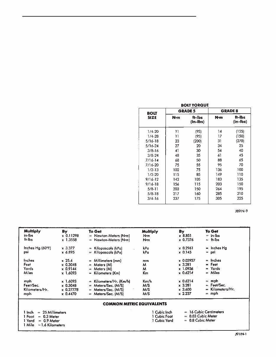
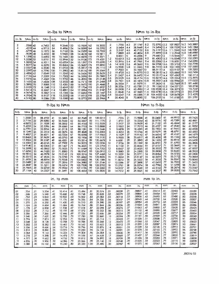
MEASUREMENT AND TORQUE SPECIFICATIONS INDEX page page Metric and English/Sae Conversion ............ 5 Specification Notations ...................... 5 Torque Specifications ....................... 5 SPECIFICATION NOTATIONS WARNING: THE USE OF INCORRECT ATTACHING HARDWARE CAN RESULT IN COMPONENT DAM- AGE AND/OR PERSONAL INJURY. It is important to retain the original attaching hardware for assembly of the components. If the at- taching hardware is not reusable, hardware with equivalent specifications must be used. METRIC AND ENGLISH/SAE CONVERSION The following chart will assist in converting metric units to equivalent English and SAE units, or vise versa. TORQUE SPECIFICATIONS TORQUE CHARTS A torque chart for fasteners is provided at the end of each group (of service information). Refer to the Standard Torque Specifications chart to determine torque values not listed in the group (Figs. 1 and 2). It is important to be aware that the torque values listed in the chart are based on clean and dry bolt threads. Reduce the torque value by 10 percent when the bolt threads are lubricated and by 20 percent if new. CONVERSION FORMULAS AND EQUIVALENT VALUES STANDARD TORQUE SPECIFICATIONS Z INTRODUCTION 5
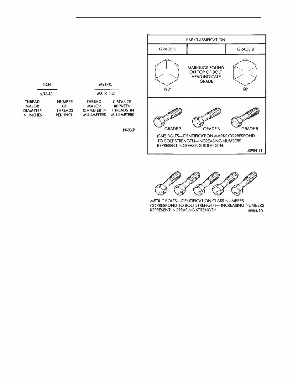
BOLT THREAD AND GRADE/CLASS IDENTIFI- CATION THREAD IDENTIFICATION SAE and metric bolt/nut threads are not the same. The difference is described in the Thread Notation chart. GRADE/CLASS IDENTIFICATION The SAE bolt strength grades range from grade 2 to grade 8. The higher the grade number, the greater the bolt strength. Identification is determined by the line marks on the top of each bolt head (Fig. 1). The actual bolt strength grade corresponds to the number of line marks plus 2. • A grade 2 bolt has no line marks on top of the bolt head • A grade 5 bolt has 3 line marks on top of the bolt head • A grade 7 bolt has 5 line marks on top of the bolt head • A grade 8 bolt has 6 line marks on top of the bolt head The most commonly used metric bolt strength classes are 9.8 and 12.9. The metric strength class identification number is imprinted on the head of the bolt (Fig. 2). The higher the class number, the greater the bolt strength. Some metric nuts are imprinted with a single-digit strength class on the nut face. METRIC CONVERSION Refer to the Metric Conversion chart to convert torque values listed in metric Newton-meters (NIm). Also, use the chart to convert between millimeters (mm) and inches (in.) Fig. 1 SAE Bolt Grade Identification Fig. 2 Metric Bolt Class Identification THREAD NOTATION—SAE AND METRIC 6 INTRODUCTION Z
The JEEP GRand CHEROKEE ZJ ZG 1993-1998 Workshop Service Manual is a comprehensive guide designed to assist users in the maintenance, repair, and troubleshooting of their vehicles. This workshop manual is specifically tailored for the JEEP GRand CHEROKEE models produced between 1993 and 1998.
With detailed step-by-step instructions and diagrams, this service manual provides users with the necessary information to perform a wide range of tasks, including engine repairs, electrical system troubleshooting, brake adjustments, and much more. Whether you are a professional mechanic or a DIY enthusiast, this workshop manual will prove to be an invaluable resource.
Featuring a user-friendly format, the JEEP GRand CHEROKEE ZJ ZG 1993-1998 Workshop Service Manual ensures that even beginners can easily understand and follow the instructions. The manual covers all aspects of the vehicle, making it a comprehensive and reliable source for any repair or maintenance needs.
Models covered:
JEEP GRand CHEROKEE ZJ 1993
JEEP GRand CHEROKEE ZJ 1994
JEEP GRand CHEROKEE ZJ 1995
JEEP GRand CHEROKEE ZJ 1996
JEEP GRand CHEROKEE ZJ 1997
JEEP GRand CHEROKEE ZJ 1998
JEEP GRand CHEROKEE ZG 1993
JEEP GRand CHEROKEE ZG 1994
JEEP GRand CHEROKEE ZG 1995
JEEP GRand CHEROKEE ZG 1996
JEEP GRand CHEROKEE ZG 1997
JEEP GRand CHEROKEE ZG 1998
Whether you need to perform routine maintenance or tackle a complex repair, the JEEP GRand CHEROKEE ZJ ZG 1993-1998 Workshop Service Manual has got you covered. Invest in this manual and ensure the longevity and optimal performance of your vehicle.
Recently Viewed
5,521,897Happy Clients
2,594,462eManuals
1,120,453Trusted Sellers
15Years in Business
Price:
Actual Price:
1993-1998 Jeep Grand Cherokee ZJ ZG Service & Repair Manual