ENGINE - 3.0L TD SERVICE INFORMATION DESCRIPTION 3.0L COMMON RAIL DIESEL ENGINE The 3.0L (183 C.I.D.) six - cylinder “common rail” direct injection engine is a 72°, overhead valve design. The engine utilize a cast aluminum cylinder block molded around cast iron piston sleeves. The engine has aluminum cross flow cylinder heads, four valves per cylinder, central injectors and dual overhead camshafts. The 3.0L is turbocharged, intercooled, and also equipped with a EGR cooler. Additional features are: • Finger Follower Actuated Valves with Hydraulic Adjusters • Counter Rotating Balance Shaft • Oil Jet Cooled Pistons • Swirl Intake Ports • Chain driven D.O.H.C. per bank of cylinders, with 4 valves per cylinder 9 - 2550 ENGINE - 3.0L TD SERVICE INFORMATION WK
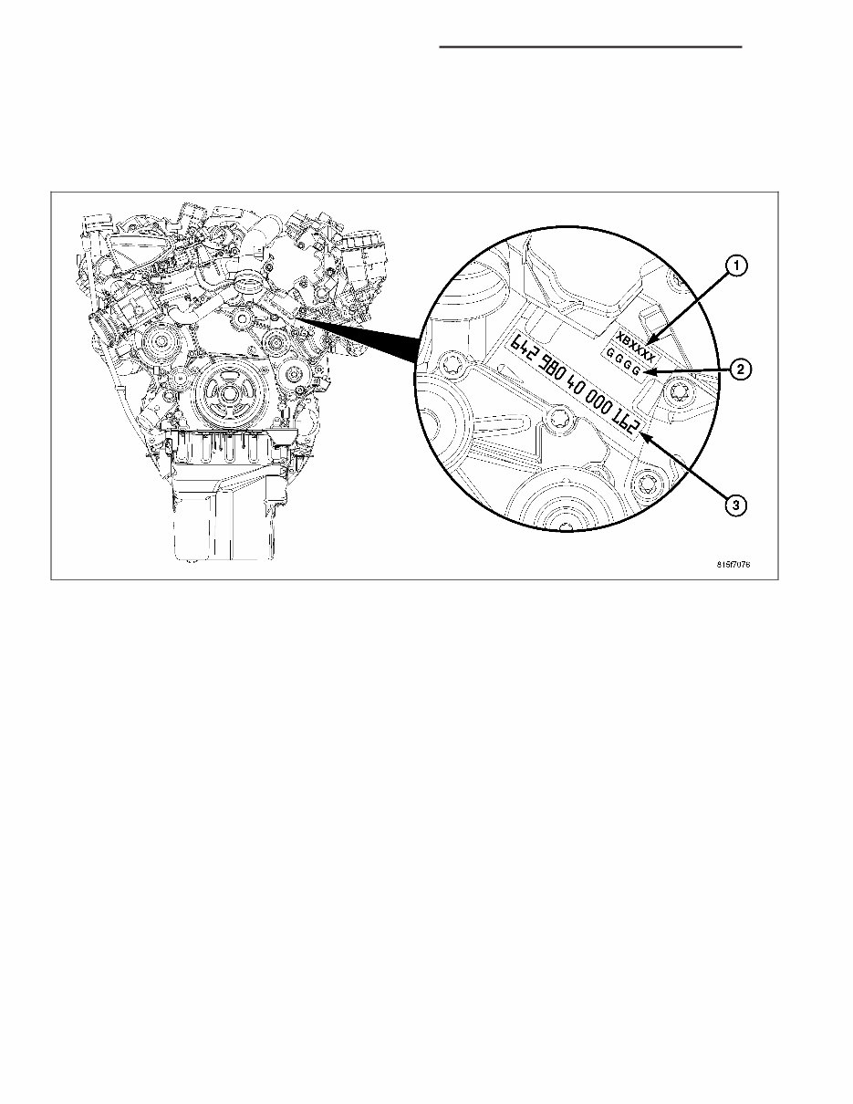
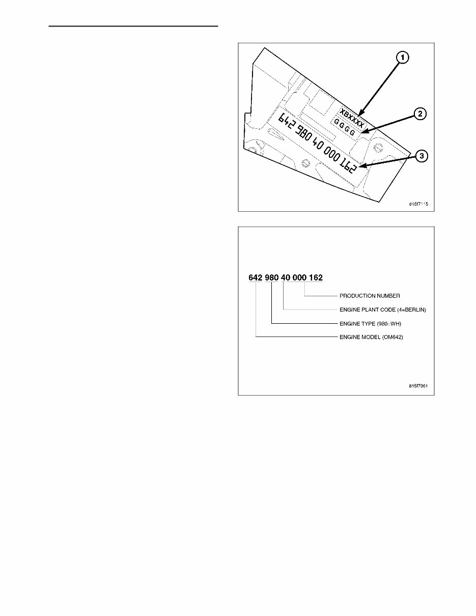
The engine identification stamp (3) for the 3.0L is located on the left side of the engine block, below the high pressure pump along with the 4 digit main bear- ing identifying stamp (2) and the 6 digit cylinder bore identifying stamp (1). The engine identification number encompasses the production number, engine plant code, engine type and engine model. WK ENGINE - 3.0L TD SERVICE INFORMATION 9 - 2551
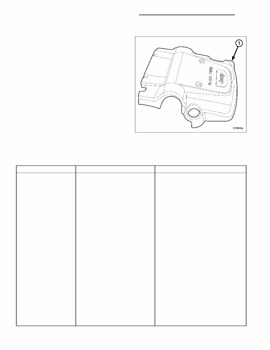
ENGINE COVER The insulated engine cover (1) is made of composite material and used cosmetically to cover the top of the engine and greatly reduce engine noise. Three brack- ets secure the cover to the engine. DIAGNOSIS AND TESTING ENGINE DIAGNOSIS - MECHANICAL CONDITION POSSIBLE CAUSES CORRECTION LUBRICATING OIL PRESSURE LOW 1. Low oil level. 1. (a) Check and fill with clean engine oil. (b) Check for a severe oil leak, worn rings (burning oil), oil leaking from the turbocharger to the intake, or other root causes for low oil level. 2. Oil viscosity thin, diluted or wrong specification. 2. (a) Verify the correct engine oil is being used. (b) Look for reduced viscosity from fuel dilution. 3. Improperly operating pressure switch/gauge. 3. Verify the pressure switch is functioning correctly. If not, replace switch/gauge. 4. Relief valve stuck open. 4. Check/replace valve. 5. If cooler was replaced, shipping plugs may have been left in cooler 5. Check/remove shipping plugs. 6. Worn oil pump. 6. Check and replace oil pump. 7. Suction tube loose or seal leaking. 7. Check and replace seal. 8. Loose main bearing cap. 8. Check and install new bearing. Tighten cap to proper torque. 9. Worn bearings or wrong bearings installed. 9. Inspect and replace connecting rod or main bearings. Check and replace directed piston cooling nozzles. 10. Directed piston cooling nozzles under piston, bad fit into main carrier. 10. Check directed piston cooling nozzles position. 9 - 2552 ENGINE - 3.0L TD SERVICE INFORMATION WK
CONDITION POSSIBLE CAUSES CORRECTION 12. Loose directed piston cooling nozzle. 12. Tighten directed piston cooling nozzle. LUBRICATING OIL PRESSURE TOO HIGH 1. Pressure switch/gauge not operating properly. 1. Verify pressure switch is functioning correctly. If not, replace switch/gauge. ENGINE BREATHER RESTRICTED 2. Engine running too cold. 2. Coolant Temperature Below Normal 3. Oil viscosity too thick. 3. Make sure the correct oil is being used. 4. Oil pressure relief valve stuck closed or binding 4. Check and replace valve. LUBRICATING OIL LOSS 1. External leaks. 1. Visually inspect for oil leaks. Repair as required. 2. Crankcase overfilled. 2. Verify that the correct dipstick is being used. 3. Incorrect oil specification or viscosity. 3. (a) Make sure the correct oil is being used. (b) Look for reduced viscosity from dilution with fuel. (c) Review/reduce oil change intervals. 4. Oil cooler leak 4. Check and replace the oil cooler. 5. High blow-by forcing oil out the breather. 5. Check the breather tube area for signs of oil loss. Perform the required repairs. 6. Turbocharger leaking oil to the air intake. 6. Inspect the air ducts for evidence of oil transfer. Repair as required (slight oil residue is normal). COMPRESSION KNOCKS 1. Air in the fuel system. 1. Identify location of air leak and repair. Do not bleed high pressure fuel system. 2. Poor quality fuel or water/gasoline contaminated fuel. 2. Verify by operating from a temporary tank with good fuel. Clean and flush the fuel tank. Replace fuel/water separator filter. 3. Engine overloaded. 3. Verify the engine load rating is not being exceeded. 4. Improperly operating injectors. 4. Check and replace misfiring/inoperative injectors. EXCESSIVE VIBRATION 1. Loose or broken engine mounts. 1. Replace engine mounts. 2. Damaged fan or improperly operating accessories. 2. Check and replace the vibrating components. 3. Improperly operating vibration damper 3. Inspect/replace vibration damper. 4. Improperly operating balance shaft 4. Inspect/replace balance shaft. 5. Improperly operating electronically controlled viscous fan drive. 5. Inspect/replace fan drive. 6. Worn or damaged generator bearing. 6. Check/replace generator. 7. Flywheel housing misaligned. 7. Check/correct flywheel alignment. 8. Loose or broken power component. 8. Inspect the crankshaft and rods for damage that causes an unbalance condition. Repair/replace as required. WK ENGINE - 3.0L TD SERVICE INFORMATION 9 - 2553
CONDITION POSSIBLE CAUSES CORRECTION 9. Worn or unbalanced driveline components. 9. Check/repair driveline components. EXCESSIVE ENGINE NOISES 1. Drive belt squeal, insufficient tension or abnormally high loading. 1. Check the automatic tensioner and inspect the drive belt. Make sure water pump, tensioner pulley, fan hub, generator and power steering pump turn freely. 2. Intake air or exhaust leaks. 2. Refer to Excessive Exhaust Smoke (Refer to 9 - ENGINE - DIAGNOSIS AND TESTING). 3. Excessive valve lash. 3. Adjust valves. Make sure the rocker arms are not bent. Replace bent or severely worn components. 4. Turbocharger noise. 4. Check turbocharger impeller and turbine wheel for housing contact. Repair/replace as required. 5. Gear train noise. 5. Visually inspect and measure gear backlash. Replace gears as required. 6. Power function knock. 6. Check/replace rod and main bearings. SMOKE DIAGNOSIS CHARTS The following charts include possible causes and corrections for excess or abnormal exhaust smoke. Small amounts of exhaust smoke (at certain times) are to be considered normal for a diesel powered engine. EXCESSIVE BLACK SMOKE POSSIBLE CAUSE CORRECTION Air filter dirty or plugged. Check and/or replace filter Air intake system restricted. Check entire air intake system including all hoses and tubes for restrictions, collapsed parts or damage. Repair/replace as necessary. Air Leak in Intake System. Check entire air intake system including all hoses and tubes for collapse, cracks, loose clamps and/or holes in rubber ducts. Also check intake manifold for loose mounting hardware. Diagnostic Trouble Codes (DTC’s) active or multiple, intermittent DTC’s. Refer to Powertrain Diagnostic Procedures Information. Engine Control Module (ECM) has incorrect calibration. Refer to Powertrain Diagnostic Procedures Information. Exhaust system restriction is above specifications. Check exhaust pipes for damage/restrictions. Repair as necessary. Fuel grade is not correct or fuel quality is poor. Temporarily change fuel brands and note condition. Change brand if necessary. Fuel injection pump malfunctioning. A DTC may have been set. If so, refer to Powertrain Diagnostic Procedures Information. Fuel injector malfunctioning. A DTC may have been set. Perform “Injector Classification Programming9 using scan tool. Also refer to Powertrain Diagnostic Procedures Information and, Return Fuel Quantity Test. Fuel injector lower washer doubled or missing. Remove and inspect injector washer. Fuel return system restricted. Check fuel return lines for restriction. Intake manifold restricted. Remove restriction. 9 - 2554 ENGINE - 3.0L TD SERVICE INFORMATION WK
EXCESSIVE BLACK SMOKE POSSIBLE CAUSE CORRECTION Manifold Air Pressure (Boost) Sensor or sensor circuit malfunctioning. A DTC should have been set. Refer to Powertrain Diagnostic Procedures Information. Turbocharger air intake restriction. Remove restriction. Turbocharger damaged. Refer to Exhaust and Turbochanger Diagnostic Procedures Turbocharger has excess build up on compressor wheel and/or diffuser vanes. Refer to Exhaust and Turbochanger Diagnostic Procedures Turbocharger wheel clearance out of specification. Refer to Exhaust and Turbochanger Diagnostic Procedures EXCESSIVE WHITE SMOKE POSSIBLE CAUSE CORRECTION Air in fuel supply: Possible leak in fuel supply side. Inspect fuel system Coolant leaking into combustion chamber. Perform pressure test of cooling system. Diagnostic Trouble Codes (DTC’s) active or multiple, intermittent DTC’s. Refer to Powertrain Diagnostic Procedures Information. In very cold ambient temperatures, engine block heater is malfunctioning (if equipped). Refer to In-Block Heater Engine coolant temperature sensor malfunctioning. A DTC should have been set. Refer to Powertrain Diagnostic Procedures Information. Also check thermostat operation. Engine Control Module (ECM) has incorrect calibration. A DTC should have been set. Refer to Powertrain Diagnostic Procedures Information. Fuel filter plugged. Refer to Powertrain Diagnostic Manual for fuel system testing. Fuel grade not correct or fuel quality is poor. Temporarily change fuel brands and note condition. Change brand if necessary. Fuel heater element or fuel heater temperature sensor malfunctioning. This will cause wax type build-up in fuel filter. Refer to Fuel Heater Testing (Refer to 14 - FUEL SYSTEM/FUEL DELIVERY/FUEL HEATER - DIAGNOSIS AND TESTING). Fuel injector malfunctioning. A DTC should have been set. Perform “Injector Identification Programming9 or 9Cylinder Cutout Test9 using scan tool to isolate individual cylinders. Also refer to Powertrain Diagnostic Procedures Information. Fuel injector hold-down(s) loose. Replace the copper washer(s)(shim) and torque to specifications. Fuel injector protrusion not correct. Check washer (shim) at bottom of fuel injector for correct thickness. Fuel injection pump malfunctioning. A DTC should have been set. Refer to Powertrain Diagnostic Procedures Information. Fuel supply side restriction. Refer to Powertrain Diagnostic Manual for fuel system testing. Intake manifold air temperature sensor malfunctioning. A DTC should have been set. Refer to Powertrain Diagnostic Procedures Information. Intake manifold heater circuit not functioning correctly in cold weather. A DTC should have been set. Refer to Powertrain Diagnostic Procedures Information. Also check heater elements for correct operation. WK ENGINE - 3.0L TD SERVICE INFORMATION 9 - 2555
EXCESSIVE WHITE SMOKE POSSIBLE CAUSE CORRECTION Intake manifold heater elements not functioning correctly in cold weather. A DTC should have been set if heater elements are malfunctioning. Refer to Powertrain Diagnostic Procedures Information. Internal engine damage (scuffed cylinder). Analyze engine oil and inspect oil filter to locate area of probable damage. Restriction in fuel supply side of fuel system. Refer to Powertrain Diagnostic Manual for fuel system testing. EXCESSIVE BLUE SMOKE POSSIBLE CAUSE CORRECTION Dirty air cleaner or restricted turbocharger intake duct. Check Air Cleaner Housing for debris and replace filter as necessary Air leak in boost system between turbocharger compressor outlet and intake manifold. Service charge air system. Obstruction in exhaust manifold. Remove exhaust manifold and inspect for blockage. Restricted turbocharger drain tube. Remove turbocharger drain tube and remove obstruction. Crankcase ventilation system plugged. Inspect oil separator system for function and clear drain back hole in cylinder head cover/intake manifold Valve seals are worn, brittle, or improperly installed. Replace valve stem oil seals Valve stems and/or guides are worn. Remove valves and inspect valves and guides. Broken or Improperly installed piston rings. Tear down engine and inspect piston rings. Excessive piston ring end gap. Remove pistons and measure piston ring end gap. Excessive cylinder liner wear and taper. Remove pistons and measure cylinder liner wear and taper. Cylinder damage. Remove pistons and inspect cylinder liner for cracks or porosity. Repair with new cylinder liner if necessary. Piston damage. Remove pistons and inspect for cracks, holes. Measure piston for out-of-round and taper. Turbocharger failure. Refer to Exhaust and Turbocharger Procedures STANDARD PROCEDURE FORM-IN-PLACE GASKETS AND SEALERS There are numerous places where form-in-place gaskets are used on the engine. Care must be taken when apply- ing form-in-place gaskets to assure obtaining the desired results. Do not use form-in-place gasket material unless specified. Bead size, continuity, and location are of great importance. Too thin a bead can result in leakage while too much can result in spill-over which can break off and obstruct fluid feed lines. A continuous bead of the proper width is essential to obtain a leak-free gasket. There are numerous types of form-in-place gasket materials that are used in the engine area. MoparT Engine RTV GEN II, MoparT ATF-RTV, and MoparT Gasket Maker gasket materials, each have different properties and can not be used in place of the other. MOPART ENGINE RTV GEN II MoparT Engine RTV GEN II is used to seal components exposed to engine oil. This material is a specially designed black silicone rubber RTV that retains adhesion and sealing properties when exposed to engine oil. Moisture in the air causes the material to cure. This material is available in three ounce tubes and has a shelf life of one year. After one year this material will not properly cure. Always inspect the package for the expiration date before use. 9 - 2556 ENGINE - 3.0L TD SERVICE INFORMATION WK
MOPART ATF RTV MoparT ATF RTV is a specifically designed black silicone rubber RTV that retains adhesion and sealing properties to seal components exposed to automatic transmission fluid, engine coolants, and moisture. This material is avail- able in three ounce tubes and has a shelf life of one year. After one year this material will not properly cure. Always inspect the package for the expiration date before use. MOPART GASKET MAKER MoparT Gasket Maker is an anaerobic type gasket material. The material cures in the absence of air when squeezed between two metallic surfaces. It will not cure if left in the uncovered tube. The anaerobic material is for use between two machined surfaces. Do not use on flexible metal flanges. MOPART GASKET SEALANT MoparT Gasket Sealant is a slow drying, permanently soft sealer. This material is recommended for sealing threaded fittings and gaskets against leakage of oil and coolant. Can be used on threaded and machined parts under all temperatures. This material is used on engines with multi-layer steel (MLS) cylinder head gaskets. This material also will prevent corrosion. MoparT Gasket Sealant is available in a 13 oz. aerosol can or 4oz./16 oz. can w/applicator. FORM-IN-PLACE GASKET AND SEALER APPLICATION Assembling parts using a form-in-place gasket requires care but it’s easier than using precut gaskets. MoparT Gasket Maker material should be applied sparingly 1 mm (0.040 in.) diameter or less of sealant to one gasket surface. Be certain the material surrounds each mounting hole. Excess material can easily be wiped off. Components should be torqued in place within 15 minutes. The use of a locating dowel is recommended during assembly to prevent smearing material off the location. MoparT Engine RTV GEN II or ATF RTV gasket material should be applied in a continuous bead approximately 3 mm (0.120 in.) in diameter. All mounting holes must be circled. For corner sealing, a 3.17 or 6.35 mm (1/8 or 1/4 in.) drop is placed in the center of the gasket contact area. Uncured sealant may be removed with a shop towel. Com- ponents should be torqued in place while the sealant is still wet to the touch (within 10 minutes). The usage of a locating dowel is recommended during assembly to prevent smearing material off the location. MoparT Gasket Sealant in an aerosol can should be applied using a thin, even coat sprayed completely over both surfaces to be joined, and both sides of a gasket. Then proceed with assembly. Material in a can w/applicator can be brushed on evenly over the sealing surfaces. Material in an aerosol can should be used on engines with multi- layer steel gaskets. REPAIR DAMAGED OR WORN THREADS CAUTION: Be sure that the tapped holes maintain the original center line. Damaged or worn threads can be repaired. Essentially, this repair consists of: • Drilling out worn or damaged threads. • Tapping the hole with a special Heli-Coil Tap, or equivalent. • Installing an insert into the tapped hole to bring the hole back to its original thread size. HYDROSTATIC LOCK CAUTION: DO NOT use the starter motor to rotate the crankshaft. Severe damage could occur. When an engine is suspected of hydrostatic lock (regardless of what caused the problem), follow the steps below. 1. Disconnect the negative cable(s) from the battery. 2. Inspect air cleaner, induction system, and intake manifold to ensure system is dry and clear of foreign material. 3. Place a shop towel around the fuel injectors to catch any fluid that may possibly be under pressure in the cyl- inder head. Remove the fuel injectors (Refer to 14 - FUEL SYSTEM/FUEL INJECTION/FUEL INJECTOR - REMOVAL). CAUTION: DO NOT use the starter motor to rotate the crankshaft. Severe damage could occur. 4. With all injectors removed, rotate the crankshaft using the crankshaft. WK ENGINE - 3.0L TD SERVICE INFORMATION 9 - 2557
The JEEP GRand CHEROKEE WK Service Repair Manual provides comprehensive guidance for maintaining and repairing your vehicle, covering models from 2005 to 2008. It includes detailed instructions, diagrams, and specifications for the engine, transmission, electrical system, suspension, and more. Whether you are a professional mechanic or a DIY enthusiast, this manual will be an invaluable resource.
Complete coverage of models from 2005 to 2008
Detailed instructions, diagrams, and illustrations
Specifications for all vehicle systems
Step-by-step procedures and troubleshooting guides
Ensure the longevity and optimal performance of your JEEP GRand CHEROKEE WK with the help of this service repair manual. Whether you need to perform regular maintenance tasks or tackle more complex repairs, this manual has you covered. Invest in the JEEP GRand CHEROKEE WK Service Repair Manual and be equipped with the knowledge and confidence to handle any maintenance or repair job on your vehicle.
Recently Viewed
5,521,897Happy Clients
2,594,462eManuals
1,120,453Trusted Sellers
15Years in Business
Price:
Actual Price:
JEEP GRand CHEROKEE WK Service Repair Manual 2005 2006 2007 2008 !!!