2005-2010 Jeep Grand Cherokee Service & Repair Manual
What's Included?
Lifetime Access
Fast Download Speeds
Online & Offline Access
Access PDF Contents & Bookmarks
Full Search Facility
Print one or all pages of your manual
2005-2010 JEEP GRAND CHEROKEE SERVICE AND REPAIR MANUAL
ENGINE 3.0L Turbo Diesel - Service Information - Grand Cherokee DESCRIPTION 3.0L COMMON RAIL DIESEL ENGINE Fig. 1: 3.0L V - 6 DIESEL ENGINE Courtesy of CHRYSLER LLC The 3.0L (183 C.I.D.) six - cylinder "common rail" direct injection engine is a 72°, overhead valve design. The engine utilize a cast aluminum cylinder block molded around cast iron piston sleeves. The engine has aluminum cross flow cylinder heads, four valves per cylinder, central injectors and dual overhead camshafts. The 3.0L is turbocharged, intercooled, and also equipped with a EGR cooler. Additional features are: Finger Follower Actuated Valves with Hydraulic Adjusters Counter Rotating Balance Shaft Oil Jet Cooled Pistons Swirl Intake Ports Chain driven D.O.H.C. per bank of cylinders, with 4 valves per cylinder 1 - CYLINDER BORE TOLERANCE IDENTIFICATION 2 - MAIN BEARING TOLERANCE IDENTIFICATION 3 - ENGINE IDENTIFICATION AND SERIAL NUMBER
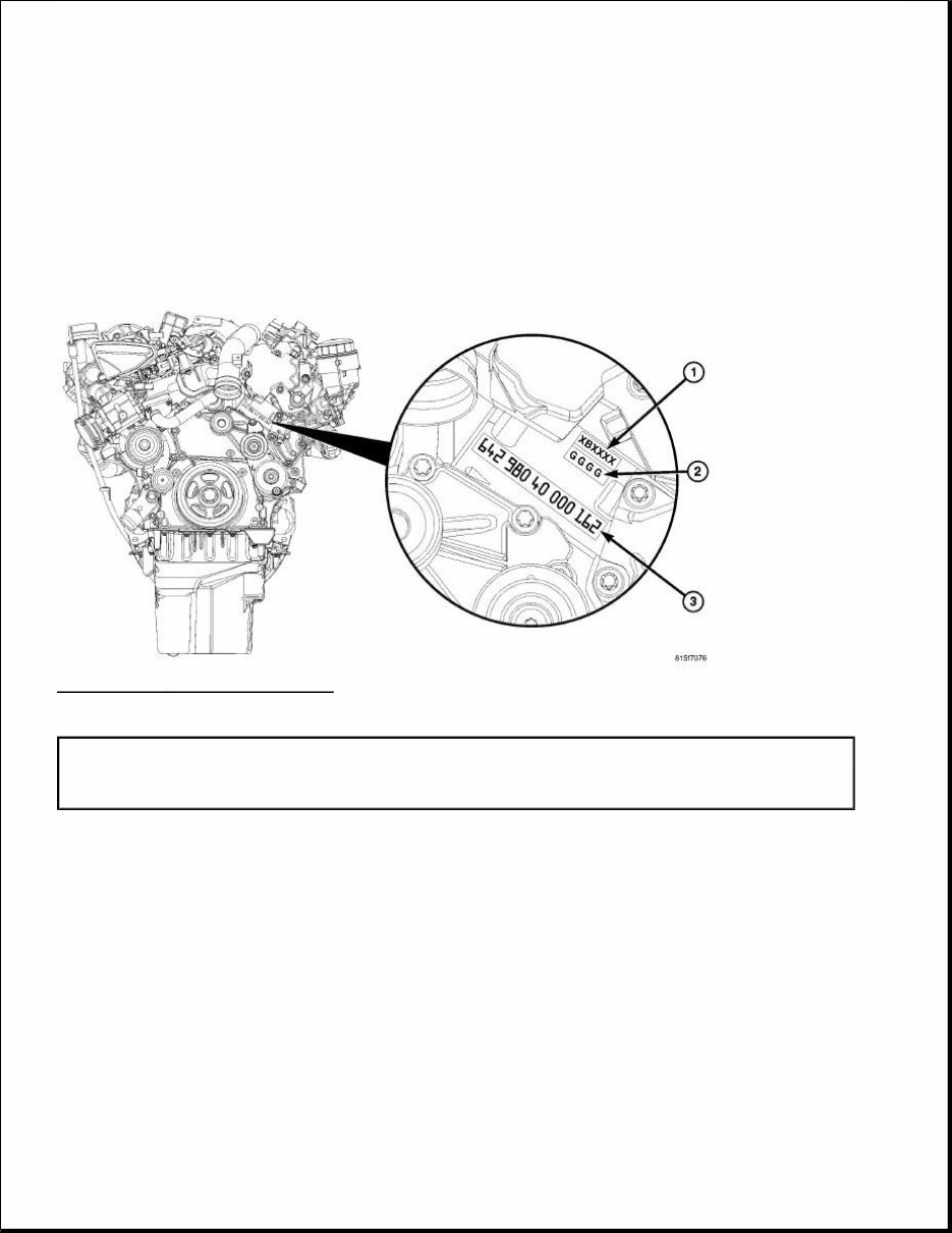
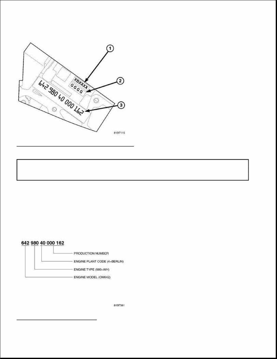
Fig. 2: ENGINE IDENTIFICATION MARKINGS Courtesy of CHRYSLER LLC The engine identification stamp (3) for the 3.0L is located on the left side of the engine block, below the high pressure pump along with the 4 digit main bearing identifying stamp (2) and the 6 digit cylinder bore identifying stamp (1). Fig. 3: ENGINE NUMBER CODE Courtesy of CHRYSLER LLC 1 - CYLINDER BORE IDENTIFICATION 2 - MAIN BEARING IDENTIFICATION 3 - ENGINE IDENTIFICATION AND SERIAL NUMBER
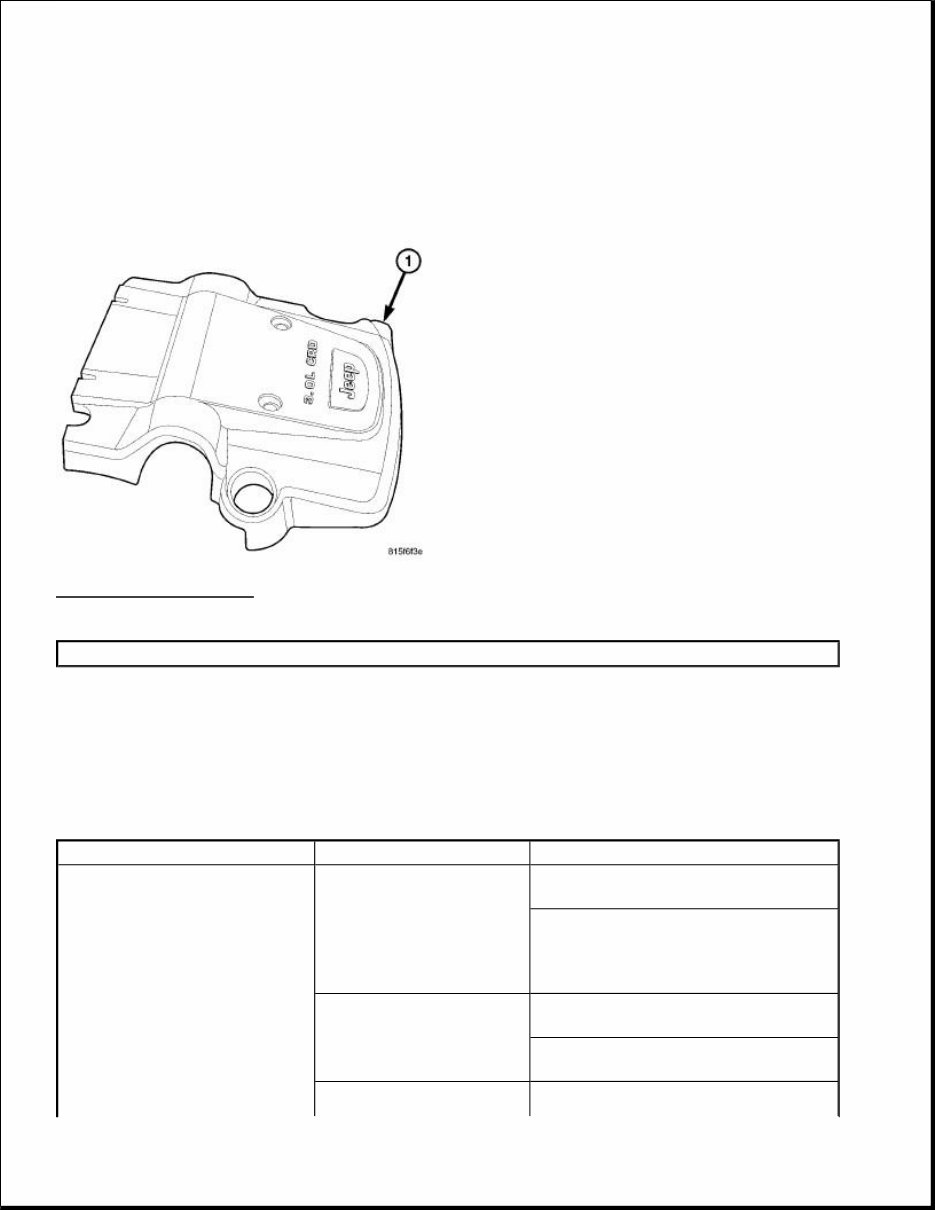
The engine identification number encompasses the production number, engine plant code, engine type and engine model. ENGINE COVER Fig. 4: ENGINE COVER Courtesy of CHRYSLER LLC The insulated engine cover (1) is made of composite material and used cosmetically to cover the top of the engine and greatly reduce engine noise. Three brackets secure the cover to the engine. DIAGNOSIS AND TESTING ENGINE DIAGNOSIS - MECHANICAL 1 - ENGINE COVER CONDITION POSSIBLE CAUSES CORRECTION LUBRICATING OIL PRESSURE LOW 1. Low oil level. 1. (a) Check and fill with clean engine oil. (b) Check for a severe oil leak, worn rings (burning oil), oil leaking from the turbocharger to the intake, or other root causes for low oil level. 2. Oil viscosity thin, diluted or wrong specification. 2. (a) Verify the correct engine oil is being used. (b) Look for reduced viscosity from fuel dilution. 3. Improperly operating 3. Verify the pressure switch is
pressure switch/gauge. functioning correctly. If not, replace switch/gauge. 4. Relief valve stuck open. 4. Check/replace valve. 5. If cooler was replaced, shipping plugs may have been left in cooler 5. Check/remove shipping plugs. 6. Worn oil pump. 6. Check and replace oil pump. 7. Suction tube loose or seal leaking. 7. Check and replace seal. 8. Loose main bearing cap. 8. Check and install new bearing. Tighten cap to proper torque. 9. Worn bearings or wrong bearings installed. 9. Inspect and replace connecting rod or main bearings. Check and replace directed piston cooling nozzles. 10. Directed piston cooling nozzles under piston, bad fit into main carrier. 10. Check directed piston cooling nozzles position. 12. Loose directed piston cooling nozzle. 12. Tighten directed piston cooling nozzle. LUBRICATING OIL PRESSURE TOO HIGH 1. Pressure switch/gauge not operating properly. 1. Verify pressure switch is functioning correctly. If not, replace switch/gauge. 2. Engine running too cold. 2. Coolant Temperature Below Normal 3. Oil viscosity too thick. 3. Make sure the correct oil is being used. 4. Oil pressure relief valve stuck closed or binding 4. Check and replace valve. LUBRICATING OIL LOSS 1. External leaks. 1. Visually inspect for oil leaks. Repair as required. 2. Crankcase overfilled. 2. Verify that the correct dipstick is being used. 3. Incorrect oil specification or viscosity. 3. (a) Make sure the correct oil is being used. (b) Look for reduced viscosity from dilution with fuel. (c) Review/reduce oil change intervals. 4. Oil cooler leak 4. Check and replace the oil cooler. 5. High blow-by forcing oil out the breather. 5. Check the breather tube area for signs of oil loss. Perform the required repairs. 6. Turbocharger leaking oil to the air intake. 6. Inspect the air ducts for evidence of oil transfer. Repair as required (slight oil residue is normal). COMPRESSION KNOCKS 1. Air in the fuel system. 1. Identify location of air leak and repair. Do not bleed high pressure fuel system. 2. Poor quality fuel or 2. Verify by operating from a temporary
water/gasoline contaminated fuel. tank with good fuel. Clean and flush the fuel tank. Replace fuel/water separator filter. 3. Engine overloaded. 3. Verify the engine load rating is not being exceeded. 4. Improperly operating injectors. 4. Check and replace misfiring/inoperative injectors. EXCESSIVE VIBRATION 1. Loose or broken engine mounts. 1. Replace engine mounts. 2. Damaged fan or improperly operating accessories. 2. Check and replace the vibrating components. 3. Improperly operating vibration damper 3. Inspect/replace vibration damper. 4. Improperly operating balance shaft 4. Inspect/replace balance shaft. 5. Improperly operating electronically controlled viscous fan drive. 5. Inspect/replace fan drive. 6. Worn or damaged generator bearing. 6. Check/replace generator. 7. Flywheel housing misaligned. 7. Check/correct flywheel alignment. 8. Loose or broken power component. 8. Inspect the crankshaft and rods for damage that causes an unbalance condition. Repair/replace as required. 9. Worn or unbalanced driveline components. 9. Check/repair driveline components. EXCESSIVE ENGINE NOISES 1. Drive belt squeal, insufficient tension or abnormally high loading. 1. Check the automatic tensioner and inspect the drive belt. Make sure water pump, tensioner pulley, fan hub, generator and power steering pump turn freely. 2. Intake air or exhaust leaks. 2. Refer to Excessive Exhaust Smoke. See Engine - Diagnosis and Testing . 3. Excessive valve lash. 3. Adjust valves. Make sure the rocker arms are not bent. Replace bent or severely worn components. 4. Turbocharger noise. 4. Check turbocharger impeller and turbine wheel for housing contact. Repair/replace as required. 5. Gear train noise. 5. Visually inspect and measure gear backlash. Replace gears as required. 6. Power function knock. 6. Check/replace rod and main bearings.
SMOKE DIAGNOSIS CHARTS The following charts include possible causes and corrections for excess or abnormal exhaust smoke. Small amounts of exhaust smoke (at certain times) are to be considered normal for a diesel powered engine. EXCESSIVE BLACK SMOKE POSSIBLE CAUSE CORRECTION Air filter dirty or plugged. Check and replace the filter if necessary. Air intake system restricted. Check entire air intake system including all hoses and tubes for restrictions, collapsed parts or damage. Repair/replace as necessary. Air Leak in Intake System. Check entire air intake system including all hoses and tubes for collapse, cracks, loose clamps, or holes in rubber ducts. Also check intake manifold for loose mounting hardware. Diagnostic Trouble Codes (DTC's) active or multiple, intermittent DTC's. Refer to DTC - Based Diagnostics/MODULE, Engine Control (ECM) - Diagnosis and Testing . Engine Control Module (ECM) has incorrect calibration. Refer to DTC - Based Diagnostics/MODULE, Engine Control (ECM) - Diagnosis and Testing . Exhaust system restriction is above specifications. Check exhaust pipes for damage/restrictions. Repair as necessary. Fuel grade is not correct or fuel quality is poor. Temporarily change fuel brands and note condition. Change brand if necessary. Fuel injection pump malfunctioning. A DTC may have been set. If so. Refer to DTC - Based Diagnostics/MODULE, Engine Control (ECM) - Diagnosis and Testing . Fuel injector malfunctioning. A DTC may have been set. Perform "Injector Classification Programming" using scan tool. Refer to DTC - Based Diagnostics/MODULE, Engine Control (ECM) - Diagnosis and Testing . Fuel injector lower washer doubled or missing. Remove and inspect injector washer. Fuel return system restricted. Check fuel return lines for restriction. Intake manifold restricted. Remove restriction. Manifold Air Pressure (Boost) Sensor or sensor circuit malfunctioning. A DTC should have been set. Refer to DTC - Based Diagnostics/MODULE, Engine Control (ECM) - Diagnosis and Testing . Turbocharger air intake restriction. Remove restriction. Turbocharger damaged. See Engine/Turbocharger System/TURBOCHARGER - Diagnosis and Testing . Turbocharger has excess build up on compressor wheel or diffuser vanes. See Engine/Turbocharger System/TURBOCHARGER - Diagnosis and Testing . Turbocharger wheel clearance out of specification. See Engine/Turbocharger System/TURBOCHARGER - Diagnosis and
Testing . EXCESSIVE WHITE SMOKE POSSIBLE CAUSE CORRECTION Air in fuel supply: Possible leak in fuel supply side. Inspect fuel system Coolant leaking into combustion chamber. Perform pressure test of cooling system. Diagnostic Trouble Codes (DTC's) active or multiple, intermittent DTC's. Refer to DTC - Based Diagnostics/MODULE, Engine Control (ECM) - Diagnosis and Testing . In very cold ambient temperatures, engine block heater is malfunctioning (if equipped). Refer to Cooling/Engine/HEATER, Engine Block - Diagnosis and Testing Engine coolant temperature sensor malfunctioning. A DTC should have been set. Refer to DTC - Based Diagnostics/MODULE, Engine Control (ECM) - Diagnosis and Testing . Also check thermostat operation. Engine Control Module (ECM) has incorrect calibration. A DTC should have been set. Refer to DTC - Based Diagnostics/MODULE, Engine Control (ECM) - Diagnosis and Testing . Fuel filter plugged. Refer to Non - DTC Diagnostics/Driveability - Diesel - Diagnosis and Testing . Fuel grade not correct or fuel quality is poor. Temporarily change fuel brands and note condition. Change brand if necessary. Fuel injector malfunctioning. A DTC should have been set. Perform "Injector Identification Programming" or "Cylinder Cutout Test" using scan tool to isolate individual cylinders. Refer to DTC - Based Diagnostics/MODULE, Engine Control (ECM) - Diagnosis and Testing . Fuel injector hold-down(s) loose. Replace the copper washer(s) (shim) and tighten to specifications. Fuel injector protrusion not correct. Check washer (shim) at bottom of fuel injector for correct thickness. Fuel injection pump malfunctioning. A DTC should have been set. Refer to DTC - Based Diagnostics/MODULE, Engine Control (ECM) - Diagnosis and Testing . Fuel supply side restriction. Refer to Non - DTC Diagnostics/Driveability - Diesel - Diagnosis and Testing for fuel system testing. Intake manifold air temperature sensor malfunctioning. A DTC should have been set. Refer to DTC - Based Diagnostics/MODULE, Engine Control (ECM) - Diagnosis and Testing . Intake manifold heater circuit not functioning correctly in cold weather. A DTC should have been set. Refer to DTC - Based Diagnostics/MODULE, Engine Control (ECM) - Diagnosis and Testing . Also check heater elements for correct operation. Intake manifold heater elements not functioning correctly in cold weather. A DTC should have been set if heater elements are malfunctioning. Refer to DTC - Based
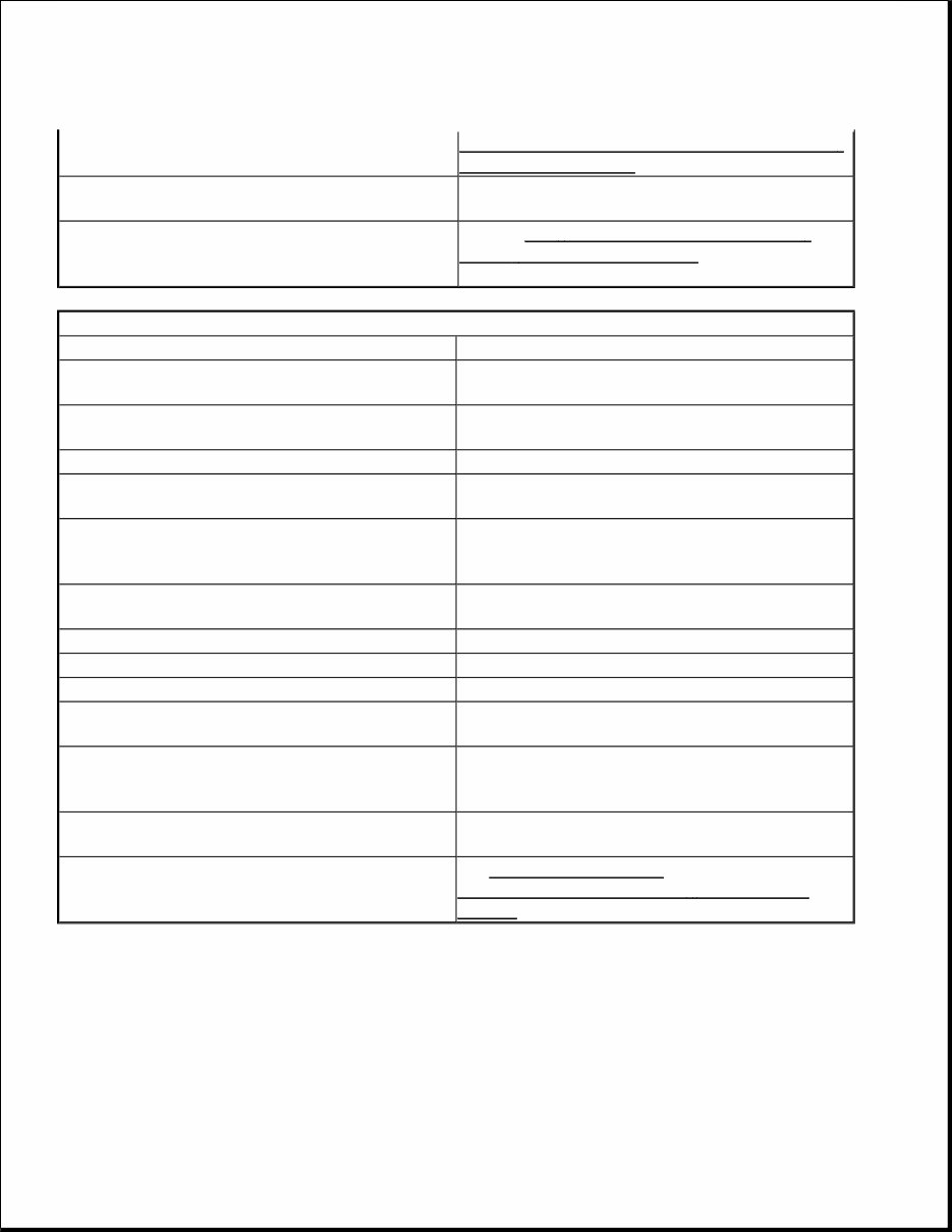
STANDARD PROCEDURE ENGINE GASKET SURFACE PREPARATION Diagnostics/MODULE, Engine Control (ECM) - Diagnosis and Testing . Internal engine damage (scuffed cylinder). Analyze engine oil and inspect oil filter to locate area of probable damage. Restriction in fuel supply side of fuel system. Refer to Non - DTC Diagnostics/Driveability - Diesel - Diagnosis and Testing for fuel system testing. EXCESSIVE BLUE SMOKE POSSIBLE CAUSE CORRECTION Dirty air cleaner or restricted turbocharger intake duct. Check Air Cleaner Housing for debris and replace filter as necessary Air leak in boost system between turbocharger compressor outlet and intake manifold. Service charge air system. Obstruction in exhaust manifold. Remove exhaust manifold and inspect for blockage. Restricted turbocharger drain tube. Remove turbocharger drain tube and remove obstruction. Crankcase ventilation system plugged. Inspect oil separator system for function and clear drain back hole in cylinder head cover/intake manifold Valve seals are worn, brittle, or improperly installed. Replace valve stem oil seals Valve stems or guides are worn. Remove valves and inspect valves and guides. Broken or Improperly installed piston rings. Tear down engine and inspect piston rings. Excessive piston ring end gap. Remove pistons and measure piston ring end gap. Excessive cylinder liner wear and taper. Remove pistons and measure cylinder liner wear and taper. Cylinder damage. Remove pistons and inspect cylinder liner for cracks or porosity. Repair with new cylinder liner if necessary. Piston damage. Remove pistons and inspect for cracks, holes. Measure piston for out-of-round and taper. Turbocharger failure. See Engine/Turbocharger System/TURBOCHARGER - Diagnosis and Testing .
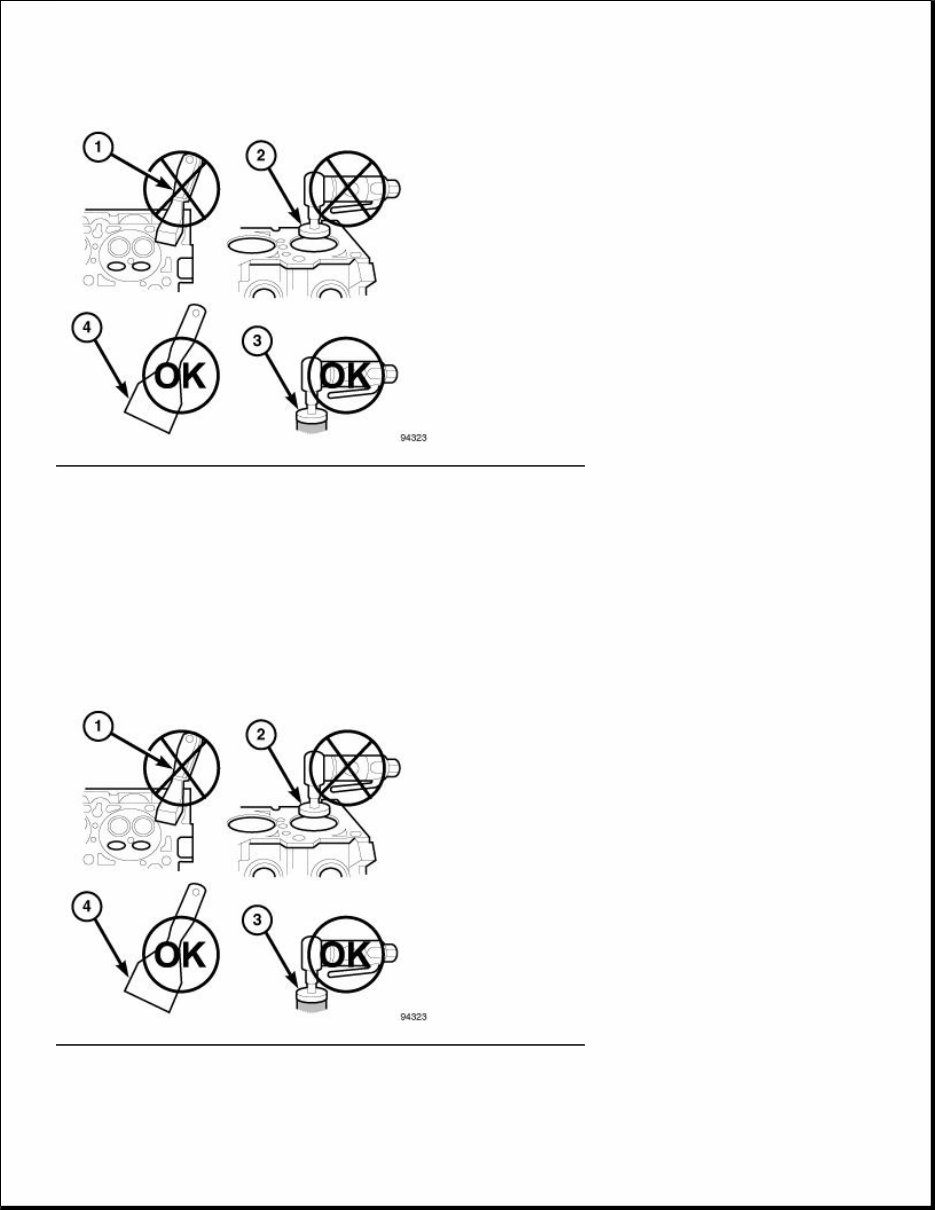
Fig. 5: PROPER TOOL USAGE FOR SURFACE PREPARATION Courtesy of CHRYSLER LLC To ensure engine gasket sealing, proper surface preparation must be performed, especially with the use of aluminum engine components and multi-layer steel cylinder head gaskets. Never use the following to clean gasket surfaces: Metal scraper (1). Abrasive pad or paper to clean cylinder block and head. High speed power tool with an abrasive pad or a wire brush (2,3). Fig. 6: PROPER TOOL USAGE FOR SURFACE PREPARATION Courtesy of CHRYSLER LLC NOTE: Multi-Layer Steel (MLS) head gaskets require a scratch free sealing surface.
Introducing the Jeep Grand Cherokee 2005-2010 Repair Service Manual!
This comprehensive manual is a must-have for all Jeep Grand Cherokee owners. Whether you're a DIY enthusiast or a professional mechanic, this manual will provide you with the necessary information to perform repairs and maintenance with ease.
The Jeep Grand Cherokee 2005-2010 Repair Service Manual covers a range of models, including:
Jeep Grand Cherokee Laredo 2005
Jeep Grand Cherokee Limited 2005
Jeep Grand Cherokee Overland 2005
Jeep Grand Cherokee SRT8 2006-2010
Jeep Grand Cherokee Laredo 2006-2010
Jeep Grand Cherokee Limited 2006-2010
Jeep Grand Cherokee Overland 2006-2010
With detailed step-by-step instructions, illustrations, and diagrams, this manual will guide you through every repair and maintenance procedure. From simple tasks like oil changes and brake pad replacements to complex repairs, you'll have all the information you need at your fingertips.
Key features of the Jeep Grand Cherokee 2005-2010 Repair Service Manual:
Comprehensive coverage of all systems and components
Easy-to-follow instructions for troubleshooting and diagnostics
Detailed diagrams and illustrations for clear understanding
Specifications and technical data for accurate repairs
Tips and recommendations for efficient maintenance
Written by industry experts with years of experience
Invest in the Jeep Grand Cherokee 2005-2010 Repair Service Manual today and take control of your vehicle's maintenance and repairs. With this manual by your side, you'll save time and money while keeping your Jeep Grand Cherokee in top condition.
Recently Viewed
5,521,897Happy Clients
2,594,462eManuals
1,120,453Trusted Sellers
15Years in Business
Price:
Actual Price:
2005-2010 Jeep Grand Cherokee Service & Repair Manual