

1996 Jeep Grand Cherokee Service & Repair Manual
What's Included?
Fast Download Speeds
Offline Viewing
Access Contents & Bookmarks
Full Search Facility
Print one or all pages of your manual

2.5L 4-CYL - VIN [P]
1993 Jeep Cherokee
1993 CHRYSLER CORP. ENGINES
2.5L 4-Cylinder
Jeep: Cherokee, Wrangler
ENGINE IDENTIFICATION
NOTE: For engine repair procedures not covered in this article,
see ENGINE OVERHAUL PROCEDURES - GENERAL INFORMATION article
in the GENERAL INFORMATION section.
Engine can be identified by eighth character of Vehicle
Identification Number (VIN). The VIN is stamped on a plate attached to
top left corner of instrument panel.
Engine code is on a machined surface on right side of
cylinder block between cylinders No. 3 and 4. This code may be
required when ordering replacement parts.
ENGINE IDENTIFICATION CODES TABLE
Application VIN Code
2.5L 4-Cylinder PFI .................................... P
Some engines are manufactured with oversize or undersize
components. These engines are identified by a letter code stamped on
oil filter boss near distributor. Letters are decoded as follows:
* "B" indicates all cylinder bores .010" (.25 mm) oversize.
* "C" indicates all camshaft bearing bores .010" (.25 mm)
oversize.
* "M" indicates all main bearing journals .010" (.25 mm)
undersize.
* "P" indicates one or more connecting rod journals .010" (.25
mm) undersize.
* "PM" indicates all crankshaft main bearing journals and one
or more connecting rod journals .010" (.25 mm) undersize.
ADJUSTMENTS
VALVE CLEARANCE ADJUSTMENT
Engine is equipped with hydraulic valve lifters. No valve
adjustment is required.
REMOVAL & INSTALLATION
NOTE: For reassembly reference, label all electrical connectors,
vacuum hoses and fuel lines before removal. Also place
mating marks on engine hood and other major assemblies
before removal.
CAUTION: When battery is disconnected, vehicle computer and memory
systems may lose memory data. Driveability problems may
exist until computer systems have completed a relearn
cycle. See COMPUTER RELEARN PROCEDURES article in GENERAL
INFORMATION before disconnecting battery.
FUEL PRESSURE RELEASE
CAUTION: Fuel system is under constant pressure. This pressure must
be released before disconnecting or servicing any fuel
supply or return system component. Wear proper eye
protection when releasing fuel system pressure.
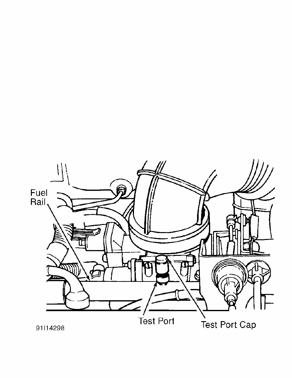
Disconnect negative battery cable. Remove fuel filler cap.
Remove cap from pressure test port on fuel rail. See Fig. 1. Place
shop towels around pressure test port to absorb spilled fuel. Press
test port valve with a small screwdriver or punch wrapped in shop
towels. Remove shop towels and dispose of properly. Install pressure
test port cap.
CAUTION: Always replace "O" rings, spacers and retainers whenever
fuel system quick-connect fittings are disconnected. Ensure
fuel connections are secure by verifying that only retainer
tabs protrude from connectors, and by pulling on tubes to
verify that they are secure.
Fig. 1: Locating Fuel Pressure Bleeding Test Port
Courtesy of Chrysler Corp.
COOLING SYSTEM BLEEDING
CAUTION: Engine coolant may be hot. To avoid scalding, carefully

release system pressure before removing radiator cap or
drain cock.
Fill radiator completely and install pressure cap. Fill
reserve/overflow tank to FULL mark. Operate engine until it reaches
normal operating temperature. Shut off engine and allow it to cool.
Recheck coolant level in reserve/overflow tank as necessary. Add
coolant ONLY when engine is cold.
ENGINE
Removal (Cherokee)
1) Remove battery and air cleaner. Remove hood. Drain cooling
system. Remove radiator hoses, coolant recovery hose and fan shroud.
Disconnect transmission fluid cooler lines (if equipped).
2) Discharge A/C system (if equipped). Discharge A/C system
using approved refrigerant recovery/recycling equipment. Remove A/C
condenser (if equipped) and radiator. Remove fan. To maintain pulley
and water pump alignment, install a 5/16 x 1/2" bolt through fan
pulley into water pump flange.
3) Disconnect heater hoses, throttle linkage, cruise control
cable (if equipped) and throttle valve rod. Disconnect wires from
starter solenoid, oxygen (O2) sensor and all fuel injection harness
connections.
4) Release fuel pressure. See FUEL PRESSURE RELEASE.
Disconnect fuel supply and return lines at fuel rail. Disconnect TDC
sensor wire connector. Remove A/C service valves and cap compressor
ports (if equipped).
5) Remove vacuum check valve from power brake booster (if
equipped). Disconnect power steering hoses at steering gear (if
equipped). Drain power steering pump reservoir. Cap power steering
hoses and fittings.
6) Tag and disconnect any remaining hoses or electrical
connectors. Raise and support vehicle. Disconnect exhaust pipe from
exhaust manifold. Remove starter and flywheel cover.
7) On automatic transmission equipped models, mark converter
and flexplate for installation reference. Remove converter-to-
flexplate bolts. On all models, remove upper bellhousing bolts and
loosen bottom bolts. Remove engine mount bolts.
8) Remove engine shock damper bracket. Lower vehicle. Attach
lifting device to engine. Raise engine from front supports. Place
support under bellhousing. Remove remaining bellhousing bolts. Remove
engine.
Removal (Wrangler)
1) Pad windshield with cloth. Raise hood and rest it against
windshield frame. Drain cooling system. Remove battery. Disconnect
wiring from alternator, ignition coil, distributor, oil pressure
sender and fuel injection wire harness.
2) Disconnect fuel line quick-connect couplings at fuel rail.
Remove engine ground strap. Remove air cleaner. Disconnect vacuum
purge hose from vapor canister tee. Unplug idle speed actuator
connector. Disconnect throttle cable and remove it from bracket.
3) Disconnect throttle rod at bellcrank. Unplug oxygen (O2)
sensor connector. Disconnect coolant hoses at radiator, intake
manifold and thermostat housing. Remove fan shroud and radiator.
Remove fan and spacer. Install a 5/16 x 1/2" bolt through fan pulley
into water pump flange to maintain pulley and water pump alignment.
4) Remove check valve from power brake booster (if equipped).
Disconnect power steering hoses at steering gear (if equipped). Drain
power steering pump reservoir. Cap power steering hoses and fittings.
5) Tag and disconnect any remaining hoses or electrical
connectors. Raise and support vehicle. Disconnect exhaust pipe from
exhaust manifold. Remove starter. Remove flywheel housing access
cover. Remove engine mount through-bolts. Remove upper bellhousing
bolts. Loosen lower bellhousing bolts.
6) Lower vehicle. Attach lifting device to engine. Raise
engine from front supports. Place support under bellhousing. Remove
remaining bellhousing bolts. Lift engine from engine compartment.
Installation (All Models)
Remove engine mount cushions from brackets to aid alignment
of engine and transmission. To complete installation, reverse removal
procedure. Adjust throttle and cruise control linkage (if equipped).
Tighten bolts to specification. See TORQUE SPECIFICATIONS table.
Refill and check fluid levels.
INTAKE MANIFOLD
Removal
1) Disconnect negative battery cable. Remove air inlet hose
at throttle body and air cleaner. Remove power steering pump with
hoses attached and wire it aside.
2) Release fuel pressure. See FUEL PRESSURE RELEASE. Remove
power steering pump brackets at water pump and intake manifold.
Disconnect fuel supply and return lines at fuel rail.
3) Disconnect accelerator cable. Unplug cruise control
connector at throttle body, using finger pressure only. Remove
crankcase ventilation and manifold pressure sensor hoses. Tag and
disconnect all wiring and hoses.
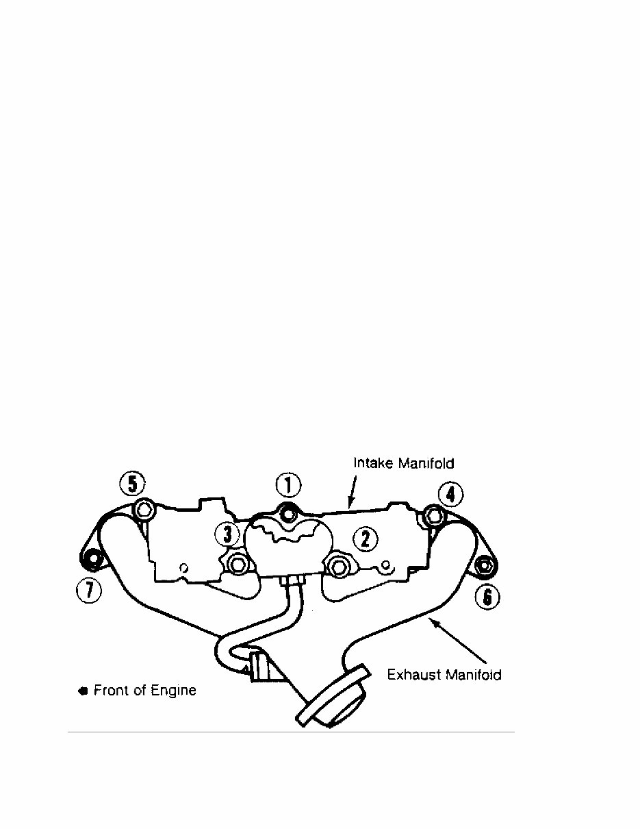
4) Remove bolts No. 2 through 5 securing intake manifold to
cylinder head. See Fig. 2. Slightly loosen bolt No. 1 and nuts No. 6
and 7. Remove intake manifold. Drain coolant from manifold.
Fig. 2: Intake & Exhaust Manifold Bolt Tightening Sequence
Courtesy of Chrysler Corp.
Installation
Ensure all gasket surfaces are clean. Install intake

manifold. Finger tighten all bolts. Tighten intake manifold bolts to
specification in correct sequence. See Fig. 2. Also see
TORQUE SPECIFICATIONS table. To complete installation, reverse removal
procedure. Fill and bleed cooling system.
EXHAUST MANIFOLD
Removal
Disconnect negative battery cable. Remove intake manifold.
See INTAKE MANIFOLD. Raise and support vehicle. Disconnect exhaust
pipe from exhaust manifold. Lower vehicle. Remove retaining nuts and
bolts. Remove exhaust manifold.
Installation
1) Clean all gasket surfaces. Install intake and exhaust
manifolds together, using NEW gasket. Ensure exhaust manifold is
centrally located over end studs and spacer. Tighten bolt No. 1 to
specification. See TORQUE SPECIFICATIONS table. Tighten bolts No. 2
through 5 to specification in sequence. See Fig. 2.
2) Install new spacers over cylinder head studs. Tighten nuts
No. 6 and 7 to specification. To complete installation, reverse
removal procedure. Start engine and check for leaks.
CYLINDER HEAD
Removal
1) Disconnect negative battery cable. Drain cooling system.
Remove accessory drive belt. Remove A/C compressor (if equipped) and
wire it aside. DO NOT discharge A/C system. Remove air cleaner.
2) Remove A/C compressor mounting bracket-to-cylinder head
bolts. Loosen A/C compressor mounting bracket-to-cylinder block bolts.
Disconnect upper radiator hose and heater hoses. Remove valve cover.
3) Remove rocker arms, bridges, pivots and push rods. Tag all
parts for installation reference. See ROCKER ARMS. Remove manifolds.
See INTAKE MANIFOLD and EXHAUST MANIFOLD.
4) Tag and disconnect spark plug wires. Remove spark plugs.
Remove cylinder head bolts. Remove cylinder head. Stuff clean lint-
free shop towels into cylinder bores.
Inspection
1) Inspect cylinder head for cracks or damage. Using
straightedge, check cylinder head for warpage across bolt holes and
diagonals. Resurface or replace cylinder head if warpage exceeds
specification or damage exists. See CYLINDER HEAD table under
ENGINE SPECIFICATIONS.
2) Cylinder head bolts may be REUSED ONLY ONCE. If this is
the first time cylinder head has been removed, put a dab of paint on
the head of each bolt. If the bolts already have paint on them, or if
it is unknown whether they have been used before, DISCARD THEM and
replace with NEW bolts.
Installation
1) Clean carbon from combustion chambers and tops of pistons.
Ensure all gasket surfaces, head bolts and head bolt holes are clean.
Install NEW cylinder head gasket with numbers or word TOP upward. DO
NOT apply sealant to cylinder head gasket. Ensure all holes align
properly.
2) Install cylinder head. Apply sealing compound to threads
of cylinder head bolt No. 7 before installation. Install cylinder head
bolts. Tighten all bolts in 3 stages in sequence to specs. See Fig. 3.
For torque specifications see TORQUE SPECIFICATIONS table.
NOTE: During the final tightening sequence, bolt No. 7 will be
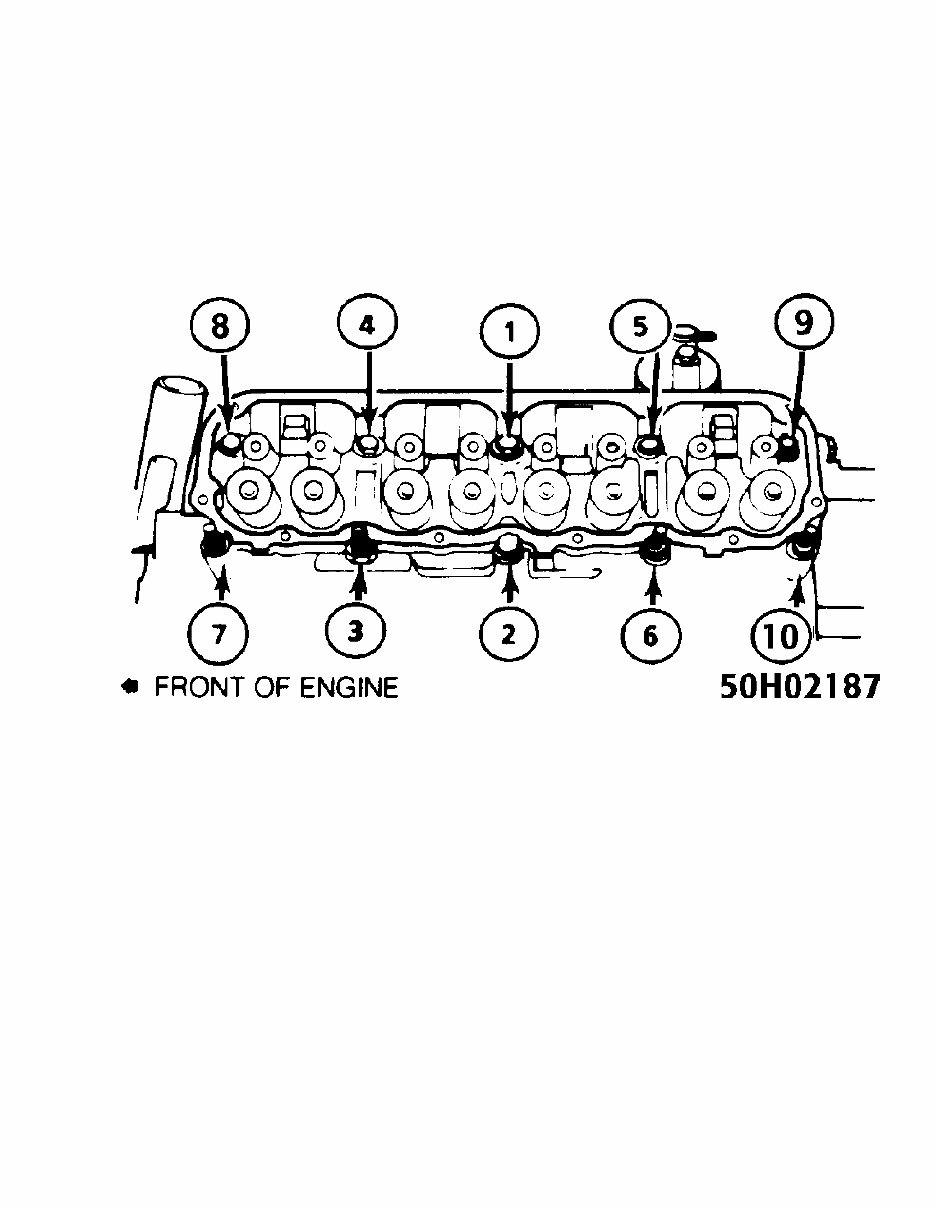
tightened to a lower torque than the others.
3) To complete installation, reverse removal procedure.
Install all valve train components into their original locations.
Refill cooling system. Remove coolant temperature sensor to bleed air
from system while filling.
Fig. 3: Cylinder Head Bolt Tightening Sequence
Courtesy of Chrysler Corp.
FRONT COVER OIL SEAL
Removal & Installation
1) Remove drive belt. Remove vibration damper. Remove
radiator shroud. Remove seal from front cover. Apply sealant to outer
diameter of new seal. Coat crankshaft lightly with oil.
2) Drive seal into front cover, using Front Cover
Aligner/Seal Installer (6139). Lightly coat seal contact area of
vibration damper with oil. Lubricate vibration damper bolt with oil
before installation. Reverse removal procedure to complete
installation. See TORQUE SPECIFICATIONS table.
TIMING CHAIN & SPROCKETS
Removal
1) Disconnect negative battery cable. Remove drive belt, fan
and hub assembly. Remove fan shroud. Remove accessory drive brackets
attached to timing case cover. Remove A/C compressor (if equipped)
with hoses attached and wire it aside. DO NOT discharge A/C system.
Remove alternator bracket assembly from cylinder head.
2) Remove vibration damper retaining bolt and washer. Remove
vibration damper and key. Remove front cover retaining bolts and front
cover. Cut oil pan gasket flush with face of cylinder block. Remove
cut-off pieces.
3) Rotate crankshaft until timing marks on crankshaft and
camshaft sprockets align. See Fig. 4. Remove oil slinger and camshaft
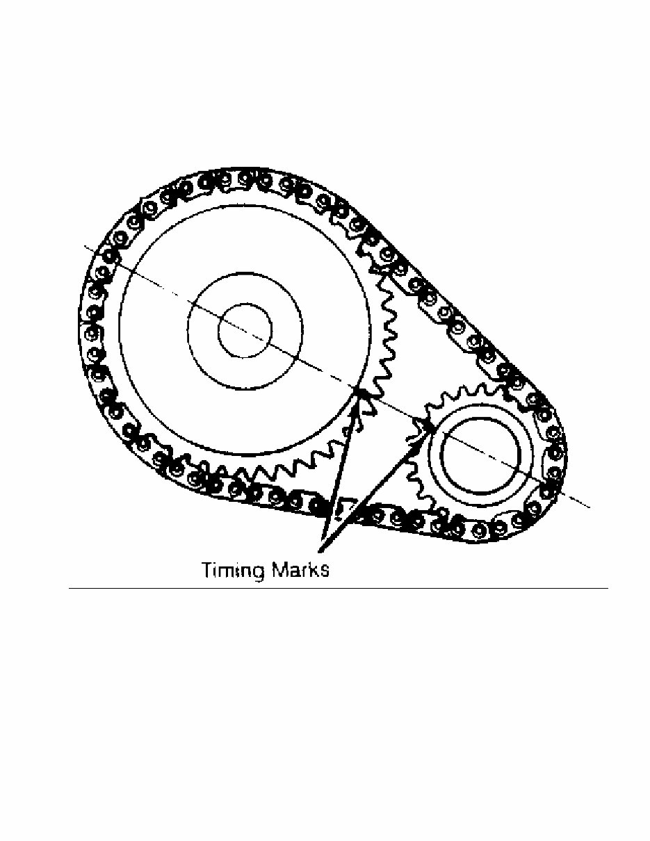
sprocket retaining bolt. Remove sprockets and chain as an assembly.
Remove front cover oil seal.
Fig. 4: Aligning Sprocket Timing Marks
Courtesy of Chrysler Corp.
Installation
1) Turn tensioner lever down to unlock position. Pull
tensioner block toward lever to compress spring. Turn lever up to lock
position. See Fig. 5. Install timing chain and sprockets as an
assembly. Ensure timing marks align. Install camshaft sprocket
retaining bolt and washer. Tighten to specification. See the
TORQUE SPECIFICATIONS table.
NOTE: Ensure chain tensioner is in unlock (down) position before
installing front cover.

Fig. 5: Locating Chain Tensioner Lock
Courtesy of Chrysler Corp.
2) Verify proper installation by rotating crankshaft until
timing mark on camshaft is at approximately one o’clock position.
Timing sprockets are installed correctly if there are 20 timing chain
pins between timing marks on both sprockets.
3) Clean all gasket surfaces. Install oil slinger. Apply
sealing compound to both sides of front cover gasket. Install gasket
onto cylinder block. Replace front section of oil pan seal with
similar piece cut from new seal.
4) Coat outer surface of NEW seal with RTV sealant and place
into position. Apply sealant where oil pan and cylinder block meet.
Place front cover onto cylinder block. Place Front Cover Aligner/Seal
Installer (6139) in front engine cover seal area.
5) Install cover retaining bolts, and tighten to
specification. To complete installation, reverse removal procedure.
Lubricate vibration damper retaining bolt before installation, and
tighten to specification. See TORQUE SPECIFICATIONS table.
ROCKER ARMS
Removal
Remove valve cover. Alternately loosen rocker arm cap screws
one turn at a time to prevent damaging bridges. Remove bridges,
pivots, rocker arms and push rods. Tag all parts for reassembly
reference.

Installation
1) Lubricate push rod ends with Mopar Engine Oil Supplement
(4318002). Install push rods into their original locations. Ensure
bottom end of each push rod is centered in valve lifter.
2) Lubricate pivot contact area of each rocker arm with
engine oil supplement. Install rocker arms, pivots and bridges into
their original locations. Loosely install cap screws, then tighten
alternately one turn at a time to specification. Reverse removal
procedure to complete installation.
3) Pour remaining engine oil supplement over entire valve
train. Supplement must remain in engine oil for at least 1000 miles
(1600 km), but need not be drained until next scheduled oil change.
CAMSHAFT
Removal
1) Disconnect negative battery cable. Drain cooling system.
Discharge A/C system (if equipped), using approved refrigerant
recovery/recycling equipment. Remove A/C condenser (if equipped) and
radiator. Mark distributor and engine block for installation
reference. Remove distributor and ignition wiring. Remove rocker arms,
bridges, pivots and push rods. See ROCKER ARMS.
2) Remove valve lifters using Hydraulic Valve Lifter
Remover/Installer (C-4129-A). Tag each valve lifter for installation
reference. Remove timing chain and sprockets. See TIMING CHAIN &
SPROCKETS. Remove camshaft.
Inspection
Inspect lobes, journals, bearings and distributor drive gear
for wear. If camshaft sprocket or chain rubs against engine front
cover, examine oil pressure relief holes in rear camshaft journal. Oil
pressure relief holes MUST be free of debris.
Installation
1) Lubricate camshaft and dip valve lifters into Mopar Engine
Oil Supplement (4318002). Install camshaft. Reverse removal procedure
to complete installation.
2) Pour remaining oil supplement over entire valve train.
Supplement must remain in engine oil for at least 1000 miles (1600
km), but need not be drained until next scheduled oil change. Refill
cooling system. Adjust ignition timing. Check for leaks.
REAR CRANKSHAFT OIL SEAL
Removal
Remove transmission, clutch housing and flywheel or
flexplate. Pry oil seal from housing. Avoid damage to surrounding
area.
Installation
Coat outer lip of replacement seal with engine oil. Using
Installer (6271), install seal flush with cylinder block. Use only NEW
bolts when installing flywheel or flexplate. Ensure felt lip is inside
flywheel mounting surface to avoid tearing seal. To complete
installation, reverse removal procedure. Tighten flywheel or flexplate
bolts to specification, then an additional 60 degrees. See the
TORQUE SPECIFICATIONS table.
WATER PUMP
Removal
Disconnect negative battery cable. Drain cooling system.
Remove fan shroud and drive belts. Remove fan assembly. Disconnect

heater hoses and lower radiator hose at water pump. Remove water pump
retaining bolts. Remove water pump.
Installation
Install water pump. Tighten bolts to specification. See
TORQUE SPECIFICATIONS table. Ensure pump turns freely. Ensure belt is
installed correctly to prevent engine overheating because water pump
rotates in wrong direction. To complete installation, reverse removal
procedure. Fill and purge air from cooling system. Remove coolant
temperature sensor to bleed air from system while filling.
OIL PAN
Removal
1) Disconnect negative battery cable. Raise and support
vehicle at side sills. Drain engine oil. Disconnect exhaust pipe at
exhaust manifold. Disconnect exhaust hanger at catalytic converter.
Lower exhaust pipe. Remove starter. Remove flywheel access cover.
2) Position jackstand directly under vibration damper. Place
wooden block between vibration damper and jackstand. Remove through
bolts from engine mounts. Raise engine enough to remove oil pan.
Remove oil pan retaining bolts. Remove oil pan by sliding it to rear.
Installation
1) Ensure all gasket surfaces are clean. Fabricate 4
alignment dowels from 1 1/2 x 1/4" bolts. Cut heads off bolts and cut
slot in end of bolts to allow removal with screwdriver. Install 2
dowels in timing cover and 2 dowels in block. Slide gasket over dowels
into position against block and timing cover.
2) Install oil pan. Install sufficient bolts to hold oil pan
in place. Remove alignment dowels. Install remaining oil pan bolts and
tighten to specification. See TORQUE SPECIFICATIONS table. To complete
installation, reverse removal procedure. Fill crankcase. Start engine.
Check for leaks.
OVERHAUL
CYLINDER HEAD
Inspection
Inspect for cracks in combustion chambers, coolant passages,
ports and exhaust valve seats. Using straightedge, check cylinder head
for warpage in several areas. Repair or replace cylinder head if
warpage exceeds specification or damage exists. See CYLINDER HEAD
table under ENGINE SPECIFICATIONS.
Valve Springs
Use Valve Spring Tester (J-22738-02) to test each valve
spring. Measure free length of each valve spring. Replace valve
springs that do not meet specifications. See VALVES & VALVE SPRINGS
table under ENGINE SPECIFICATIONS.
Valve Stem Oil Seals
Replace valve stem oil seals if they have deteriorated or
whenever valves are serviced. Oil seals are marked INT and EXH for
intake and exhaust valves, respectively. Oversize oil seals must be
used with valves having .015" (.38 mm) oversize stems.
Valve Guides
Measure diameter of valve guide approximately 3/8" (10 mm)
from valve spring side of head, both parallel and at right angle to
long axis of head. If difference between measurements exceeds .0025"
You're Reading a Preview
What's Included?
Fast Download Speeds
Offline Viewing
Access Contents & Bookmarks
Full Search Facility
Print one or all pages of your manual
$30.99
Viewed 16 Times Today


Secure transaction
What's Included?
Fast Download Speeds
Offline Viewing
Access Contents & Bookmarks
Full Search Facility
Print one or all pages of your manual
$30.99
The Jeep Grand Cherokee 1996 Factory Service Manual is your ultimate guide to maintaining and repairing your Jeep Grand Cherokee 1996 model. This comprehensive manual is specifically designed for the 1996 Grand Cherokee models and provides detailed information on all aspects of the vehicle.
- Provides detailed instructions for performing basic maintenance tasks such as oil changes, filter replacements, and tire rotations.
- Covers advanced repair procedures including engine and transmission overhauls, electrical system troubleshooting, and suspension repairs.
- Includes comprehensive diagrams, illustrations, and photographs to help you understand each step of the repair process.
- Offers troubleshooting guides to help you diagnose and solve common problems with your Grand Cherokee.
- Gives you access to factory specifications, tolerances, and torque settings, ensuring that you work on your vehicle with the highest level of accuracy and precision.
- Compatible with all Jeep Grand Cherokee models released in 1996.
Whether you are a professional mechanic or a Jeep enthusiast looking to do some DIY repairs, the Jeep Grand Cherokee 1996 Factory Service Manual is a must-have resource. With its comprehensive coverage, detailed instructions, and accurate specifications, this manual will help you keep your Grand Cherokee in top condition for years to come.


