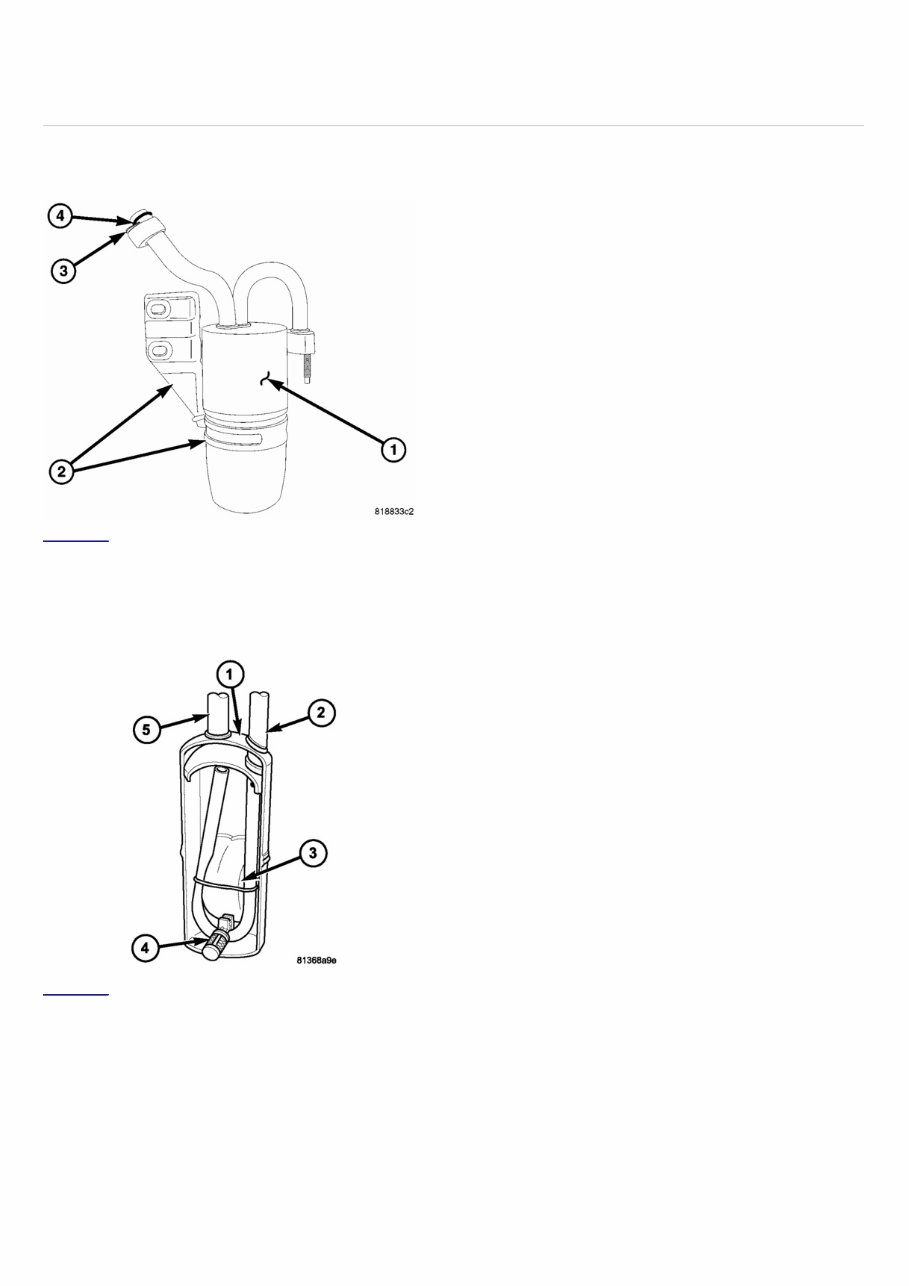
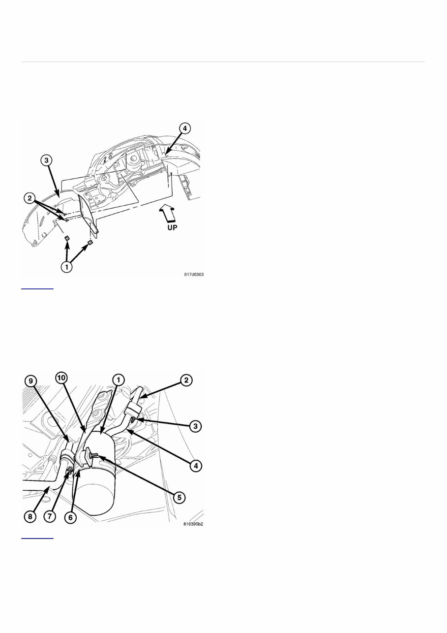
2007 Jeep COMPASS Submodel: LIMITED | Engine Type: L4 | Liters: 2.4 Fuel Delivery: FI | Fuel: GAS DESCRIPTION Click to enlarge To protect the A/C compressor from any liquid slugging, an A/C accumulator (1) is used in this A/C system to retain any refrigerant that may exit from the evaporator in a liquid state. The A/C accumulator is mounted below the engine compartment behind the right side of the front fascia. A band and mounting bracket (2) secures the A/C accumulator to the right front frame rail and t he connections are sealed by use of metal gaskets (3) and rubber O-rings (4). OPERATION Click to enlarge Typical A/C accumulator shown. Refrigerant enters the A/C accumulator (1) mostly as a low pressure vapor through the inlet tube (2). Any liquid, oil-laden refrigerant falls to the bottom of the canister, which acts as a separator. A desiccant bag (3) is mounted inside the accumulator canister to absorb any moisture which may have entered and become trapped within the refrigerant system. A filter (4) is also mounted inside the canister to trap any foreign material that may have entered the refrigerant system during assembly. The low pressure vapor exits the A/C accumulator through the outlet tube (5). Replacement of the refrigerant line O-ring seals and gaskets is required anytime a refrigerant line is opened. Failure to replace the rubber O-ring seals and metal gaskets could result in a refrigerant system leak. The A/C accumulator has no serviceable parts except for the O-ring seals and gaskets. The O-ring seals used on the connections are made from a special type of rubber not affected by R- 134a refrigerant. The O-ring seals and gaskets must be replaced whenever the A/C accumulator is removed and installed. The A/C accumulator cannot be repaired and must be replaced if found to be leaking or damaged, or if an internal failure of the A/C compressor has occurred.
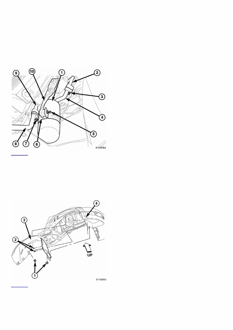
2007 Jeep COMPASS Submodel: LIMITED | Engine Type: L4 | Liters: 2.4 Fuel Delivery: FI | Fuel: GAS REMOVAL Warning: Review safety precautions and warnings in this group before performing this procedure (refer to 24 - HEATING & AIR CONDITIONING/PLUMBING - WARNING) and (refer to 24 - HEATING & AIR CONDITIONING/PLUMBING - CAUTION). Failure to follow the warnings and cautions could result in possible personal injury or death. Click to enlarge 1. Disconnect and isolate the negative battery cable. 2. Recover the refrigerant from the refrigerant system (refer to 24 - HEATING & AIR CONDITIONING/PLUMBING - STANDARD PROCEDURE - REFRIGERANT SYSTEM RECOVERY). 3. Raise and support the vehicle. 4. Remove the right front wheel (refer to 22 - TIRES/WHEELS - REMOVAL). 5. Remove the three push-pin retainers (1) and three screws (2) that secure the front portion of the right front wheelhouse splash shield (3) to body (4) and position the front of the wheelhouse splash shield out of the way to gain access to the A/C accumulator. Click to enlarge 1. Remove the nut (7) that secures the lower A/C suction line (8) to the accumulator outlet tube (9) and disconnect the suction line from the accumulator tube. 2. Remove the bolt (5) and retaining band (6) that secure the A/C accumulator to the mounting bracket (10). 3. Remove the nut (3) that secures the upper A/C suction line (2) to the accumulator inlet tube (4) and disconnect the suction line from the accumulator tube. 4. If necessary remove the accumulator mounting bracket from the body. 5. Remove and discard the O-ring seals and gaskets and install plugs in, or tape over the opened refrigerant line fittings and the accumulator ports.
INSTALLATION Caution: Be certain to adjust the refrigerant oil level when servicing the A/C refrigerant system (refer to 24 - HEATING & AIR CONDITIONING/PLUMBING/REFRIGERANT OIL - STANDARD PROCEDURE - REFRIGERANT OIL LEVEL). Failure to properly adjust the refrigerant oil level will prevent the A/C system from operating as designed and can cause serious A/C compressor damage. Caution: The A/C accumulator must be replaced if an internal failure of the A/C compressor has occurred. Failure to replace the A/C accumulator can cause serious A/C compressor damage. When replacing multiple A/C system components, refer to the Refrigerant Oil Capacities chart to determine how much oil should be added to the refrigerant system (refer to 24 - HEATING & AIR CONDITIONING/PLUMBING/REFRIGERANT OIL - STANDARD PROCEDURE - REFRIGERANT OIL LEVEL). If only the A/C accumulator is being replaced, add 30 milliliters (1.0 fluid ounce) of refrigerant oil to the refrigerant system. Use only refrigerant oil of the type recommended for the A/C compressor in the vehicle. Replacement of the refrigerant line O-ring seals and gaskets is required anytime a refrigerant line is opened. Failure to replace the rubber O-ring seals and metal gaskets could result in a refrigerant system leak. Click to enlarge 1. If removed, install the accumulator mounting bracket (10). Tighten the retaining bolts to 15 N·m (11 ft. lbs.). 2. Remove the tape or plugs from all of the opened refrigerant line fittings and the accumulator ports. 3. Lubricate new rubber O-ring seals with clean refrigerant oil and install them and new gaskets onto the suction line and accumulator fittings. Use only the specified O- rings as they are made of a special material for the R-134a system. Use only refrigerant oil of the type recommended for the A/C compressor in the vehicle. 4. Connect the upper A/C suction line (2) to the accumulator inlet tube (4) and install the retaining nut (3). Tighten the nut to 5 N·m (44 in. lbs.). 5. Install the retaining band (6) and bolt (5) that secure the A/C accumulator (1) to the mounting bracket. Tighten the bolt to 8 N·m (71 in. lbs.). 6. Connect the lower A/C suction line (8) to the accumulator outlet tube (9) and install the retaining nut (7). Tighten the nut to 5 N·m (44 in. lbs.). Click to enlarge 1. Reposition the front of the right front wheel house splash shield (3) to the body (4) and install the three push-pin retainers (1) and the three screws (2). Tighten the screws securely. 2. Install the right front wheel (refer to 22 - TIRES/WHEELS - INSTALLATION). 3. Lower the vehicle. 4. Reconnect the negative battery cable.
Caution: Do NOT run the engine with a vacuum pump in operation or with a vacuum present within the A/C system. Failure to follow this caution will result in serious A/C compressor damage. 1. Evacuate the refrigerant system (refer to 24 - HEATING & AIR CONDITIONING/PLUMBING - STANDARD PROCEDURE - REFRIGERANT SYSTEM EVACUATE). 2. If the A/C accumulator is being replaced, add 30 milliliters (1.0 fluid ounce) of refrigerant oil to the refrigerant system. When replacing multiple A/C system components, refer to the Refrigerant Oil Capacities chart to determine how much oil should be added to the refrigerant system (refer to 24 - HEATING & AIR CONDITIONING/PLUMBING/REFRIGERANT OIL - STANDARD PROCEDURE - REFRIGERANT OIL LEVEL). Use only refrigerant oil of the type recommended for the A/C compressor in the vehicle. 3. Charge the refrigerant system (refer to 24 - HEATING & AIR CONDITIONING/PLUMBING - STANDARD PROCEDURE - REFRIGERANT SYSTEM CHARGE).
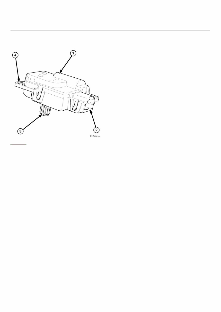
2007 Jeep COMPASS Submodel: LIMITED | Engine Type: L4 | Liters: 2.4 Fuel Delivery: FI | Fuel: GAS DESCRIPTION Click to enlarge The recirculation door actuator (1) is a reversible, 12 volt direct current (DC) servo motor, which is connected directly to the pivot shaft lever of the recirculation-air door. The recirculation door actuator is located on the right side of the HVAC air inlet housing. The recirculation door actuator is contained within a black molded plastic housing with an integral wire connector receptacle (2), an output shaft with splines (3) that connect it to the recirculation door and three integral mounting tabs (4) that allow the actuator to be secured to the air inlet housing. The recirculation door actuator does not require mechanical indexing to the recirculation-air door, as it is electronically calibrated by the A/C-heater control. OPERATION The recirculation door actuator is connected to the A/C-heater control through the vehicle electrical system by a dedicated two-wire lead and connector of the instrument panel wire harness. The recirculation door actuator can move the recirculation-air door in two directions. When the A/C-heater control pulls the voltage on one side of the motor connection high and the other connection low, the recirculation-air door will move in one direction. When the A/C-heater control reverses the polarity of the voltage to the motor, the recirculation-air door moves in the opposite direction. Once the A/C-heater control makes the voltage to both connections high or both connections low, the recirculation-air door stops and will not move. The A/C-heater control uses a pulse-count positioning system to monitor the operation and relative position of the recirculation door actuator and the recirculation-air door. The A/C-heater control learns the recirculation-air door stop positions during the calibration procedure and will store a diagnostic trouble code (DTC) for any problems it detects in the recirculation door actuator circuits ( refer to 24 - HVAC Electrical Diagnostics for more information). The recirculation door actuator cannot be adjusted or repaired and it must be replaced if found inoperative or damaged.
Fixing problems in your vehicle is a do-it-approach with the Auto Repair Manuals. These manuals contain comprehensive instructions and procedures on how to fix the problems in your ride. Whether you are a professional mechanic or a DIY enthusiast, these manuals can come in handy, especially when you have to do immediate repairs to your car.
The durability of your vehicle is unquestionable, but you also know that no matter how tough they are, constant use can cause them to deteriorate. When this happens, and ultimately it will, you will have to replace them. Some car parts are very simple to mount and do not require professional help. By having a trusty repair manual, you not only save money but you also get to experience the fun of do-it-yourself projects.
A repair manual comes with comprehensive details regarding technical data, diagrams, a complete list of car parts, and pictures. Even the most novice car mechanic can easily follow the step-by-step guides, which are made simple by the illustrations and drawings. You can find a complete list of accessories that can further enhance the performance of your engine.
The information contained in this repair manual is the same as the ones used by the engineers of the company. This repair manual covers all these sections, containing hundreds of photos and more:
Maintenance
Engine
Control System
Mechanical
Fuel Service Specifications
Emission Control
Intake Exhaust Cooling
Lube
Ignition Starting Charging
Auto Transmission Clutch
Manual Transmission
Transfer Propeller Shaft
Drive Shaft
Differential
Axle Suspension
Tire & Wheel
Brake Control
Brake
Parking Brake
Steering Column
Power Steering
Air Condition
Suppl Restraint System
Seat Belt
Engine Immobilizer
Cruise Control
Wiper & Washer
Door Lock
Meter Audio/Visual
Horn
Windshield/Glass Mirror
Instrument Panel
Seat
Engine Hood/ Door
Exterior & Interior
Electrical
Multiplex/ Can Communication
And much more...
Additional information about this service repair manual:
Compatible: All Versions of Windows AND Mac
Printable: Yes
Language: English
Requirements: Adobe Reader and Win (they are free online)
Auto Repair Manuals can save you a lot of time. These packages are complete with all your car information needs. You will surely enjoy browsing through the pages and learning how to repair the different parts of your car. It makes you up-to-date and more knowledgeable. Now, you don't have to rely on your mechanic for the simplest car repair. You can do it at the comfort of your garage. It's a fun activity that allows you to enter the realm of your car. All pages are printable, so print off what you need and take it with you into the garage or workshop. This manual will never get dirty and rip as you can keep it safely on your PC and print the pages you need in a matter of seconds.




 Lifetime Access




