1997-1999 Jeep Cherokee XJ Workshop Repair Service Manual
What's Included?
Lifetime Access
Fast Download Speeds
Offline Viewing
Access Contents & Bookmarks
Full Search Facility
Print one or all pages of your manual
ELECTRICAL GROUP INDEX Group Group AUDIO SYSTEMS ........................ 8F BATTERY/STARTER/GENERATOR SERVICE .... 8B BATTERY/STARTING/CHARGING SYSTEMS DIAGNOSTICS ......................... 8A CHIME/BUZZER WARNING SYSTEMS ........ 8U HORNS ................................ 8G IGNITION SYSTEMS ...................... 8D INSTRUMENT PANEL AND GAUGES ......... 8E LAMPS ................................ 8L OVERHEAD CONSOLE .................... 8C POWER LOCKS .......................... 8P POWER MIRRORS ....................... 8T POWER SEATS .......................... 8R POWER WINDOWS ....................... 8S REAR WINDOW DEFOGGER ............... 8N RESTRAINT SYSTEMS ................... 8M TURN SIGNAL AND HAZARD WARNING SYSTEMS ............................. 8J VEHICLE SPEED CONTROL SYSTEM ......... 8H WIPER AND WASHER SYSTEMS ............ 8K XJ WIRING DIAGRAMS-LEFT HAND DRIVE . . . 8W XJ WIRING DIAGRAMS-RIGHT HAND DRIVE . 8W YJ WIRING DIAGRAMS .................. 8W BATTERY/STARTING/CHARGING SYSTEMS DIAGNOSTICS CONTENTS page page BATTERY ............................... 2 CHARGING SYSTEM ..................... 17 IGNITION-OFF DRAW .................... 10 SPECIFICATIONS ........................ 23 STARTING SYSTEM ...................... 11 USING ON-BOARD DIAGNOSTIC SYSTEM .... 22 GENERAL INFORMATION The battery, starting, and charging systems operate with one another; therefore, they must be tested as a complete system. In order for the vehicle to start and charge properly, all of the components involved in these systems must perform within specifications. Group 8A covers battery, starting (Fig. 1) and charging (Fig. 2) system diagnostic procedures. These procedures include the most basic conventional diag- nostic methods, to On-Board Diagnostics (OBD) built into the Powertrain Control Module (PCM). Use of an induction milliamp ammeter, volt/ohmmeter, battery charger, carbon pile rheostat (load tester), and 12- volt test lamp will be required. All OBD-sensed systems are monitored by the PCM. Each monitored circuit is assigned a Diagnos- tic Trouble Code (DTC). The PCM will store a DTC in electronic memory for any failure it detects. See Us- ing On-Board Diagnostic System in this group for more information. J ELECTRICAL 8A - 1
BATTERY GENERAL INFORMATION The storage battery is a device used to store elec- trical energy potential in a chemical form. When an electrical load is applied to the battery terminals, an electrochemical reaction occurs within the battery. This reaction causes the battery to discharge electri- cal current. The battery is made up of 6 individual cells that are connected in series. Each cell contains positively charged plate groups made of lead oxide, and nega- tively charged plate groups made of sponge lead. These dissimilar metal plates are submerged in a sulfuric acid and water solution called electrolyte. As the battery discharges, a gradual chemical change takes place within each cell. The sulfuric acid in the electrolyte combines with the plate materials, causing both plates to change to lead sulfate. At the same time, oxygen from the positive plate material combines with hydrogen from the sulfuric acid, caus- ing the electrolyte to become mainly water. The chemical changes within the battery are caused by movement of excess or free electrons be- tween the positive and negative plate groups. This movement of electrons produces a flow of electrical current through the load device attached to the bat- tery terminals. As the plate materials become more similar chem- ically, and the electrolyte becomes less acid, the volt- age potential of each cell is reduced. However, by charging the battery with a voltage higher than that of the battery, the process is reversed. Charging the battery gradually changes the sul- fated lead plates back into sponge lead and lead ox- ide, and the water back into sulfuric acid. This action restores the difference in electron charges deposited on the plates, and the voltage potential of the battery cells. For a battery to remain useful, it must be able to produce high-amperage current over an extended pe- riod. A battery must also be able to accept a charge, so that its voltage potential may be restored. In addition to producing and storing electrical en- ergy, the battery serves as a capacitor or voltage sta- bilizer for the vehicle electrical system. It absorbs abnormal or transient voltages caused by switching of any of the vehicle’s electrical components. The battery is vented to release excess gas that is created when the battery is being charged or dis- Fig. 1 Starting System Components (Typical) Fig. 2 Charging System Components (Typical) 8A - 2 BATTERY/STARTING/CHARGING SYSTEMS DIAGNOSTICS J
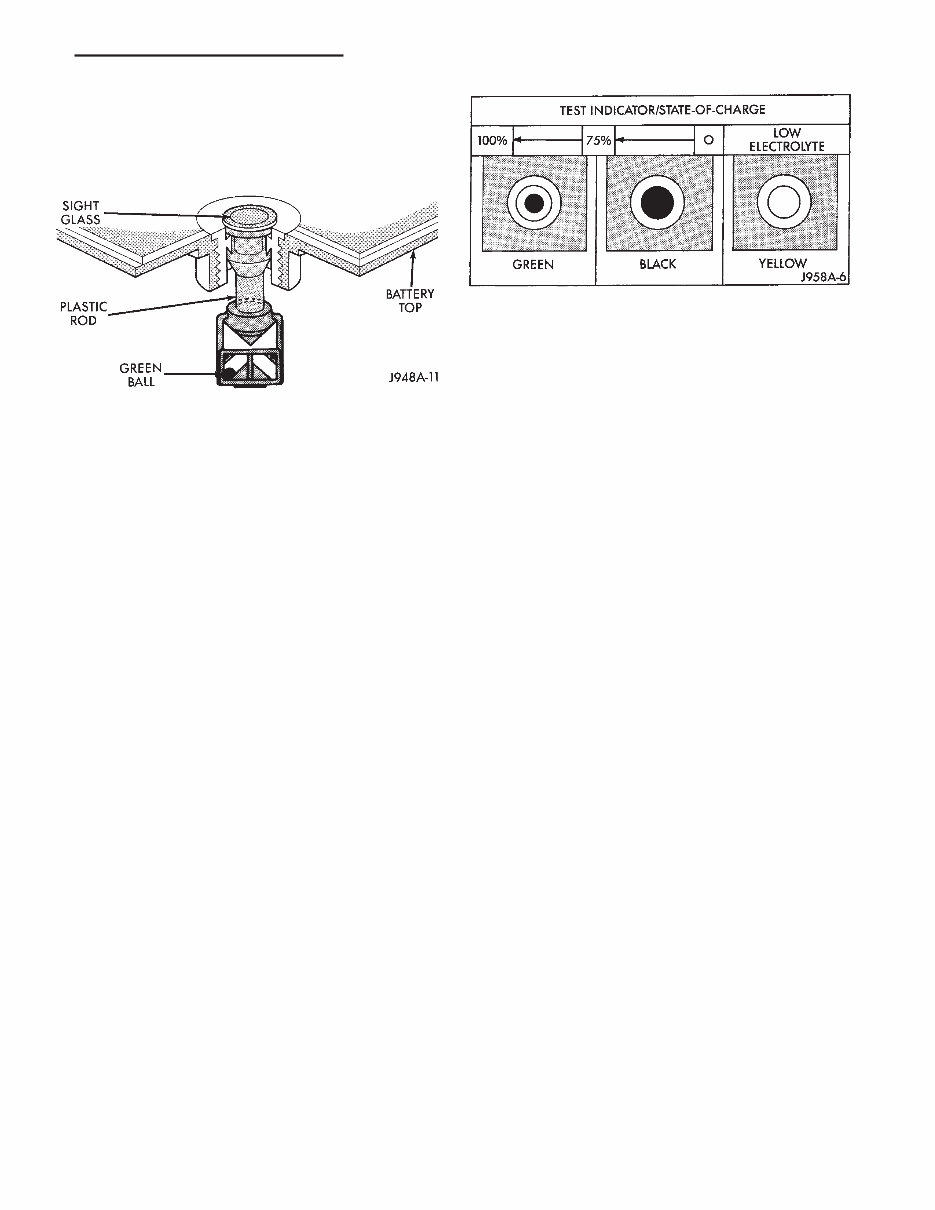
charged. However, even with these vents, hydrogen gas can collect in or around the battery. If hydrogen gas is exposed to flame or sparks, it can ignite. If the electrolyte level is low, the battery could arc internally and explode. If the battery is equipped with removable cell caps, add distilled water when- ever the electrolyte level is below the top of the plates. If the battery cell caps cannot be removed, the battery must be replaced when the electrolyte level is low. WARNING: DO NOT ATTEMPT TO ASSIST BOOST, CHARGE, OR TEST BATTERY WHEN ELECTRO- LYTE LEVEL IS BELOW THE TOP OF THE PLATES. PERSONAL INJURY MAY OCCUR. BATTERY RATINGS Currently, there are 2 commonly accepted methods for rating and comparing battery performance. These ratings are called Cold Cranking Amperage (CCA), and Reserve Capacity (RC). Be certain that a replace- ment battery has CCA and RC ratings that equal or exceed the original equipment specification for the vehicle being serviced. See Battery Classifications and Ratings charts in Specifications at the back of this group. COLD CRANKING AMPERAGE The Cold Cranking Amperage (CCA) rating speci- fies how much current (in amperes) the battery can deliver for 30 seconds at -17.7°C (0°F). Terminal volt- age must not fall below 7.2 volts during or after the 30 second discharge. The CCA required is generally higher as engine displacement increases, depending also upon the starter current draw requirements. RESERVE CAPACITY The Reserve Capacity (RC) rating specifies the time (in minutes) it takes for battery terminal volt- age to fall below 10.2 volts at a discharge rate of 25 amps. RC is determined with the battery fully- charged at 26.7°C (80°F). This rating estimates how long the battery might last after a charging system failure, under minimum electrical load. DIAGNOSIS The battery must be completely charged and the top, posts, and terminal clamps should be properly cleaned before diagnostic procedures are performed. Refer to Group 8B - Battery/Starter/Generator Ser- vice for more information. The condition of a battery is determined by two cri- teria: (1) State-Of-Charge This can be determined by viewing the built-in test indicator, by checking spe- cific gravity of the electrolyte (hydrometer test), or by checking battery voltage (open circuit voltage test). (2) Cranking Capacity This can be determined by performing a battery load test, which measures the ability of the battery to supply high-amperage current. If the battery has a built-in test indicator, use this test first. If it has no test indicator, but has remov- able cell caps, perform the hydrometer test first. If cell caps are not removable, or a hydrometer is not available, perform the open circuit voltage test first. The battery must be charged before proceeding with a load test if: • the built-in test indicator has a black or dark color visible • the temperature corrected specific gravity is less than 1.235 • the open circuit voltage is less than 12.4 volts. A battery that will not accept a charge is faulty and further testing is not required. A battery that is fully-charged, but does not pass the load test is faulty and must be replaced. Completely discharged batteries may take several hours to accept a charge. See Charging Completely Discharged Battery. A battery is fully-charged when: • all cells are gassing freely during charging • a green color is visible in the sight glass of the built-in test indicator • three corrected specific gravity tests, taken at 1-hour intervals, indicate no increase in specific grav- ity • open circuit voltage is 12.4 volts or greater. ABNORMAL BATTERY DISCHARGING Any of the following conditions can result in abnor- mal battery discharging: (1) Corroded battery posts and terminals. (2) Loose or worn generator drive belt. (3) Electrical loads that exceed the output of the charging system, possibly due to equipment installed after manufacture or repeated short trip use. (4) Slow driving speeds (heavy traffic conditions) or prolonged idling with high-amperage draw systems in use. (5) Faulty circuit or component causing excessive ignition-off draw. See Ignition-Off Draw in this group for diagnosis. (6) Faulty charging system. (7) Faulty or incorrect battery. BUILT-IN TEST INDICATOR A test indicator (hydrometer) built into the top of the battery case, provides visual information for bat- tery testing (Fig. 1). It is important when using the test indicator that the battery be level and have a clean sight glass to see correct indications. Additional light may be required to view indicator. J BATTERY/STARTING/CHARGING SYSTEMS DIAGNOSTICS 8A - 3
BATTERY DIAGNOSIS 8A - 4 BATTERY/STARTING/CHARGING SYSTEMS DIAGNOSTICS J
WARNING: DO NOT USE OPEN FLAME AS A SOURCE OF ADDITIONAL LIGHT FOR VIEWING TEST INDICATOR. EXPLOSIVE HYDROGEN GAS MAY BE PRESENT IN THE AREA SURROUNDING BATTERY. Like a hydrometer, the built-in test indicator mea- sures the specific gravity of the electrolyte. Specific gravity will indicate battery state-of-charge. How- ever, the test indicator will not indicate cranking ca- pacity of the battery. See Load Test in this group for more information. Look into the sight glass and note the color of the indicator (Fig. 2). Refer to the following description, as the color indicates: GREEN—indicates 75% to 100% state-of-charge. The battery is adequately charged for further test- ing or return to use. If the vehicle will not crank for a minimum of 15 seconds with a fully-charged bat- tery, perform Load Test. BLACK OR DARK—indicates 0% to 75% state-of- charge. The battery is inadequately charged and must be charged until green indicator (Fig. 2) is visible in sight glass (12.4 volts or more) before the battery is tested further or returned to use. See Abnormal Bat- tery Discharging in this group to diagnose cause of discharged condition. YELLOW OR BRIGHT—indicates low electrolyte level. The electrolyte level in the battery is below test in- dicator (Fig. 2). A maintenance-free battery with non- removable cell caps must be replaced if electrolyte level is low. Water can be added to a low-mainte- nance battery with removable cell caps. A low electro- lyte level may be caused by an over-charging condition. See Charging System in this group to di- agnose an over-charging condition. WARNING: DO NOT ATTEMPT TO CHARGE, TEST, OR ASSIST BOOST BATTERY WHEN YELLOW OR BRIGHT COLOR IS VISIBLE IN SIGHT GLASS OF TEST INDICATOR. LOW ELECTROLYTE LEVEL CAN ALLOW BATTERY TO ARC INTERNALLY AND EX- PLODE. PERSONAL INJURY MAY OCCUR. HYDROMETER TEST The hydrometer test reveals the battery state-of- charge by measuring the specific gravity of the elec- trolyte. This test cannot be performed on batteries with non-removable cell caps. If battery has non-re- movable cell caps, see Built-In Test Indicator or Open Circuit Voltage Test. Specific gravity is a comparison of the density of the electrolyte to the density of pure water. Pure wa- ter has a specific gravity of 1.000, and sulfuric acid has a specific gravity of 1.835. Sulfuric acid makes up approximately 35% of the electrolyte by weight, or 24% by volume. In a fully-charged battery the electrolyte will have a temperature corrected specific gravity of 1.260 to 1.290. However, a specific gravity of 1.235 or above is satisfactory for battery load testing and/or return to service. Before testing, visually inspect battery for any damage (cracked case or cover, loose posts, etc.) that would cause the battery to be faulty. Then remove cell caps and check electrolyte level. Add distilled wa- ter if electrolyte level is below the top of the battery plates. To use the hydrometer correctly, hold it with the top surface of the electrolyte at eye level. Refer to the hydrometer manufacturer’s instructions for correct use of hydrometer. Remove only enough electrolyte from the battery so the float is off the bottom of the hydrometer barrel with pressure on the bulb re- leased. Exercise care when inserting the tip of the hydrom- eter into a cell to avoid damaging the plate separa- tors. Damaged plate separators can cause premature battery failure. Hydrometer floats are generally calibrated to indi- cate the specific gravity correctly only at 26.7°C (80°F). When testing the specific gravity at any other temperature, a correction factor is required. The correction factor is approximately a specific gravity value of 0.004, referred to as 4 points of spe- cific gravity. For each 5.5°C above 26.7°C (10°F above 80°F), add 4 points. For each 5.5°C below 26.7°C (10°F below 80°F), subtract 4 points. Always correct Fig. 1 Built-In Test Indicator Fig. 2 Built-In Test Indicator Sight Glass J BATTERY/STARTING/CHARGING SYSTEMS DIAGNOSTICS 8A - 5
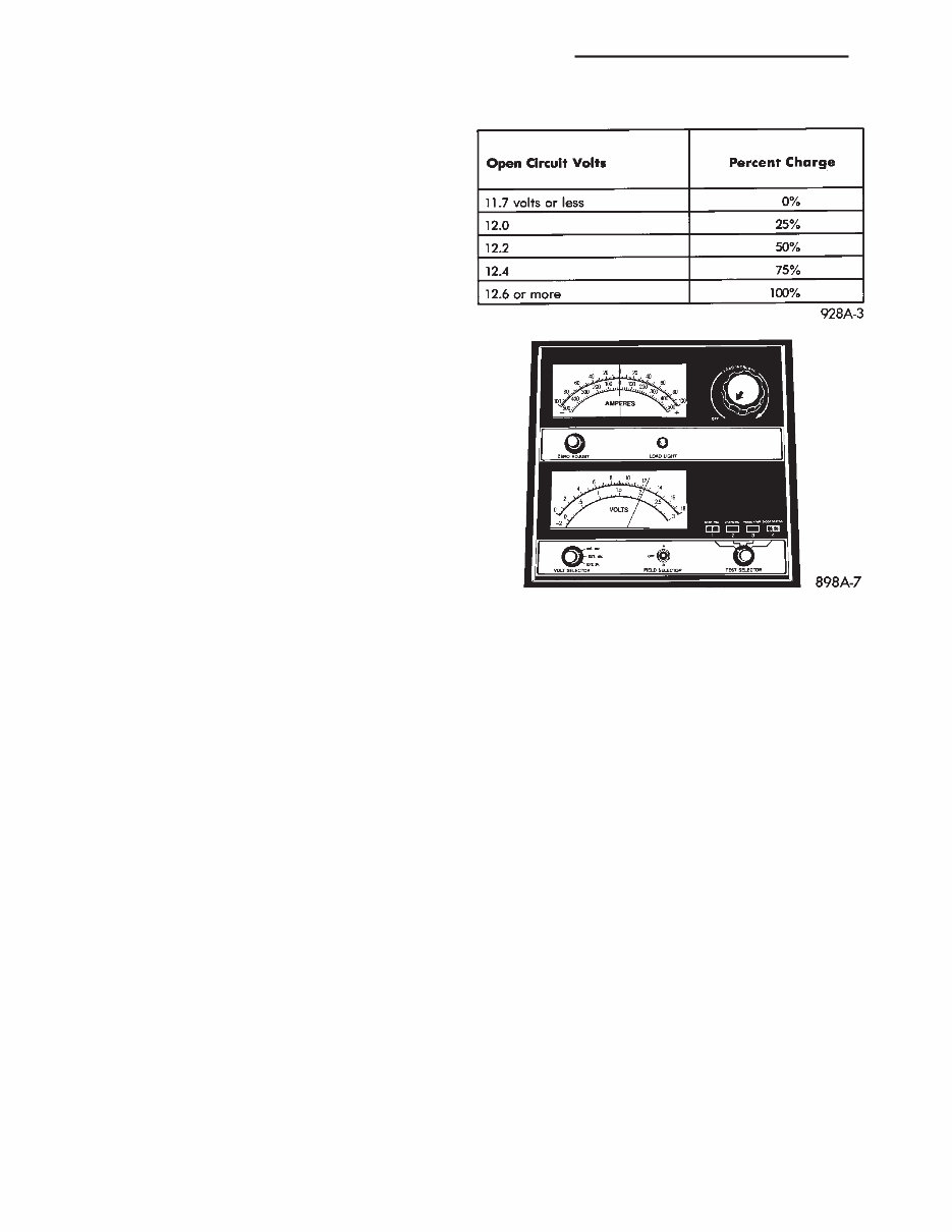
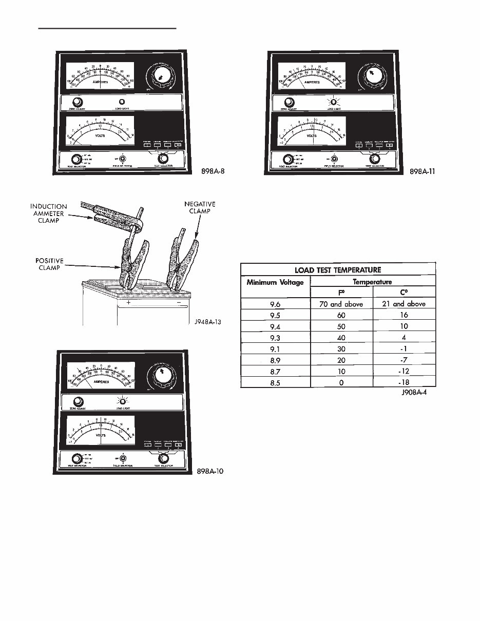
the specific gravity for temperature variation. Test the specific gravity of the electrolyte in each battery cell. Example: A battery is tested at -12.2°C (10°F) and has a specific gravity of 1.240. Determine the actual specific gravity as follows: (1) Determine the number of degrees above or be- low 26.7°C (80°F): 26.6°C - -12.2°C = 38.8°C (80°F - 10°F = 70°F) (2) Divide the result from step 1 by 5.5 (10): 38.8°C/5.5 = 7 (70°F/10 = 7) (3) Multiply the result from step 2 by the temper- ature correction factor (0.004): 7 x 0.004 = 0.028 (4) The temperature at testing was below 26.7°C (80°F); therefore, the temperature correction is sub- tracted: 1.240 - 0.028 = 1.212 The corrected specific gravity of the battery in this example is 1.212. If the specific gravity of all cells is above 1.235, but variation between cells is more than 50 points (0.050), the battery should be replaced. If the specific gravity of one or more cells is less than 1.235, charge the battery at a rate of approxi- mately 5 amperes. Continue charging until 3 consec- utive specific gravity tests, taken at 1-hour intervals, are constant. If the cell specific gravity variation is more than 50 points (0.050) at the end of the charge period, replace the battery. When the specific gravity of all cells is above 1.235, and cell variation is less than 50 points (0.050), the battery may be load tested. OPEN CIRCUIT VOLTAGE TEST A battery open circuit voltage (no load) test will show state-of-charge of a battery. This test can be used in place of the hydrometer test if a hydrometer is not available, or for maintenance-free batteries with non-removable cell caps. Before proceeding with this test or load test, completely charge battery as described in Bat- tery Charging in this group. Test battery open circuit voltage as follows: (1) Before measuring open circuit voltage the sur- face charge must be removed from the battery. Turn headlamps on for 15 seconds, then allow up to 5 min- utes for voltage to stabilize. (2) Remove both battery cables, negative first. (3) Using a voltmeter connected to the battery posts (refer to instructions provided with voltmeter) measure open circuit voltage (Fig. 3). See Open Circuit Voltage chart. This voltage read- ing will indicate state-of-charge, but will not reveal cranking capacity. If a battery has an open circuit voltage reading of 12.4 volts or greater, it may be load tested. A battery that will not endure a load test is faulty and must be replaced. LOAD TEST A battery load test will verify battery cranking ca- pacity. The test is based on the Cold Cranking Am- perage (CCA) rating of the battery. See Battery Classifications and Ratings chart in Specifications, at the back of this group. WARNING: IF BATTERY SHOWS SIGNS OF FREEZ- ING, LEAKING, LOOSE POSTS, OR LOW ELECTRO- LYTE LEVEL, DO NOT LOAD TEST. PERSONAL INJURY AND/OR VEHICLE DAMAGE MAY RESULT. Before performing load test, the battery must be FULLY-CHARGED. (1) Remove both battery cables, negative first. Bat- tery top and posts should be clean. (2) Connect a suitable volt-ammeter-load tester (Fig. 4) to the battery posts (Fig. 5). Refer to operat- ing instructions provided with the tester being used. Check the open circuit voltage (no load) of the bat- tery. Open circuit voltage must be 12.4 volts or greater. (3) Rotate the load control knob (carbon pile rheo- stat) to apply a 300 amp load for 15 seconds, then re- turn the control knob to OFF (Fig. 6). This will remove the surface charge from the battery. (4) Allow the battery to stabilize to open circuit voltage. It may take up to 5 minutes for voltage to stabilize. OPEN CIRCUIT VOLTAGE Fig. 3 Testing Open Circuit Voltage 8A - 6 BATTERY/STARTING/CHARGING SYSTEMS DIAGNOSTICS J
(5) Rotate the load control knob to maintain a load equal to 50% of CCA rating (Fig. 7). After 15 seconds, record the loaded voltage reading, then return the load control knob to OFF. (6) Voltage drop will vary with battery tempera- ture at the time of the load test. Battery temperature can be estimated by the ambient temperature over the past several hours. If the battery has been charged, boosted, or loaded a few minutes prior to test, the battery will be somewhat warmer. See Load Test Temperature chart for proper loaded voltage reading. (7) If the voltmeter reading falls below 9.6 volts, at a minimum battery temperature of 21°C (70°F), re- place the battery. BATTERY CHARGING A battery is fully-charged when: • all cells are gassing freely during charging • a green color is visible in sight glass of built-in test indicator • three corrected specific gravity tests, taken at 1-hour intervals, indicate no increase in specific grav- ity • open circuit voltage is 12.4 volts or above. WARNING: DO NOT ASSIST BOOST OR CHARGE A BATTERY THAT HAS LOW ELECTROLYTE LEVEL OR IS FROZEN. BATTERY MAY ARC INTERNALLY AND EXPLODE. WARNING: EXPLOSIVE HYDROGEN GAS FORMS IN AND AROUND BATTERY. DO NOT SMOKE, USE FLAME, OR CREATE SPARKS NEAR BATTERY. Fig. 4 Volt-Amps-Load Tester (Typical) Fig. 5 Volt-Ammeter-Load Tester Connections Fig. 6 Remove Surface Charge from Battery Fig. 7 Load 50% CCA Rating - Note Voltage J BATTERY/STARTING/CHARGING SYSTEMS DIAGNOSTICS 8A - 7
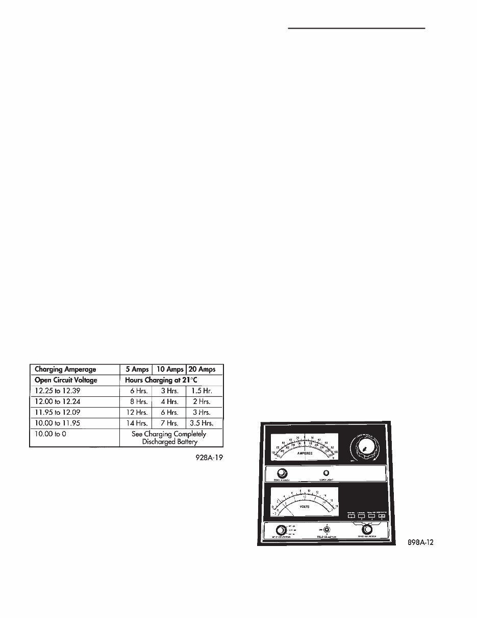
WARNING: POISONOUS AND CAUSTIC. BATTERY CONTAINS SULFURIC ACID. AVOID CONTACT WITH SKIN, EYES, OR CLOTHING. IN EVENT OF CON- TACT, FLUSH WITH WATER AND CALL PHYSICIAN IMMEDIATELY. KEEP OUT OF REACH OF CHIL- DREN. CAUTION: Always disconnect the battery negative cable before charging battery to avoid damage to electrical system components. Do not exceed 16.0 volts while charging battery. Battery electrolyte will bubble inside battery case during normal battery charging. If the electrolyte boils, or is discharged from the vent holes while charging, immediately reduce charging rate or turn OFF charger and evaluate battery condition. Battery should not be hot to the touch. If the battery feels hot to the touch, turn OFF charger and let battery cool before continuing charging operation. Some battery chargers are equipped with polarity sensing circuitry. This circuitry protects the charger and/or battery from being damaged if improperly con- nected. If the battery state-of-charge is too low for the po- larity sensing circuitry to detect, the charger will not operate. This makes it appear that the battery will not accept charging current. Refer to instructions provided with the battery charger being used to by- pass the polarity sensing circuitry. After the battery has been charged to 12.4 volts or greater, perform a load test to determine cranking capacity. If the battery will endure a load test, return the battery to use. If the battery will not endure a load test, it must be replaced. Clean and inspect battery holddowns, tray, termi- nals, posts, and top before completing service. Refer to Group 8B - Battery/Starter/Generator Service for more information. CHARGING TIME REQUIRED The time required to charge a battery will vary, de- pending upon the following factors: (1) Battery Capacity—A completely discharged heavy-duty battery requires twice the recharging time of a small capacity battery. WARNING: NEVER EXCEED 20 AMPS WHEN CHARGING A COLD (-1°C/30°F) BATTERY. PER- SONAL INJURY MAY RESULT. (2) Temperature—A longer time will be needed to charge a battery at -18°C (0°F) than at 27°C (80°F). When a fast charger is connected to a cold battery, current accepted by the battery will be very low at first. As the battery warms, it will accept a higher charging current rate. (3) Charger Capacity—A charger that supplies only 5 amperes will require a longer charging time. A charger that supplies 20 amperes or more requires a shorter charging time. (4) State-Of-Charge—A completely discharged battery requires more charging time than a partially discharged battery. Electrolyte is nearly pure water in a completely discharged battery. At first, the charging current (amperage) will be low. As the bat- tery charges, the specific gravity of the electrolyte will gradually rise. CHARGING COMPLETELY DISCHARGED BATTERY The following procedure should be used to recharge a completely discharged battery. Unless this proce- dure is properly followed, a good battery may be needlessly replaced. (1) Measure voltage at battery posts with a voltme- ter, accurate to 1/10 (0.10) volt (Fig. 8). If the reading is below 10 volts, the charge current will be low. It could take some time before the battery accepts a current greater than a few milliamperes. Such low current may not be detectable on ammeters built into many chargers. (2) Disconnect battery negative cable. Connect charger leads. Some battery chargers are equipped BATTERY CHARGING TIME TABLE Fig. 8 Voltmeter Accurate to 1/10 Volt Connected 8A - 8 BATTERY/STARTING/CHARGING SYSTEMS DIAGNOSTICS J
with polarity sensing circuitry. This circuitry protects the charger and/or battery from being damaged if im- properly connected. If the battery state-of-charge is too low for the polarity sensing circuitry to detect, the charger will not operate. This makes it appear that the battery will not accept charging current. Re- fer to the instructions provided with the battery charger to bypass the polarity sensing circuitry. (3) Battery chargers vary in the amount of voltage and current they provide. The amount of time re- quired for a battery to accept measurable charger current at various voltages is shown in Charge Rate chart. If charge current is still not measurable at end of charging times, the battery should be replaced. If charge current is measurable during charging time, the battery may be good and charging should be com- pleted in the normal manner. CHARGE RATE J BATTERY/STARTING/CHARGING SYSTEMS DIAGNOSTICS 8A - 9
IGNITION-OFF DRAW GENERAL INFORMATION Ignition-Off Draw (IOD) refers to power being drained from the battery with the ignition switch turned OFF. A normal vehicle electrical system will draw from 5 to 20 milliamps (0.005 - 0.020 amps). This is with the ignition switch in the OFF position, and all non-ignition controlled circuits in proper working order. The 20 milliamps are needed to sup- ply PCM memory, digital clock memory, and electron- ically-tuned radio memory. A vehicle that has not been operated for approxi- mately 20 days, may discharge the battery to an in- adequate level. When a vehicle will not be used for 20 days or more (stored), remove the IOD fuse in the Power Distribution Center (PDC). This will reduce battery discharging. Excessive battery drain can be caused by: • electrical items left on • faulty or improperly adjusted switches • internally shorted generator • intermittent shorts in the wiring. If the IOD is over 20 milliamps, the problem must be found and corrected before replacing a battery. In most cases, the battery can be charged and returned to service. DIAGNOSIS Testing for high-amperage IOD must be per- formed first to prevent damage to most milli- amp meters. (1) Verify that all electrical accessories are off. Turn off all lamps, remove ignition key, and close all doors. If the vehicle is equipped with illuminated en- try or electronically-tuned radio, allow the systems to automatically shut off (time out). This may take up to 3 minutes. (2) Determine that the underhood lamp is operat- ing properly, then disconnect or remove bulb. (3) Disconnect negative cable from battery. (4) Connect a typical 12-volt test lamp (low-watt- age bulb) between the negative cable clamp and the battery negative terminal. Make sure that the doors remain closed so that illuminated entry is not acti- vated. The test lamp may light brightly for up to 3 min- utes, or may not light at all, depending upon the ve- hicle’s electrical equipment. The term brightly, as used throughout the following tests, implies the brightness of the test lamp will be the same as if it were connected across the battery. The test lamp must be securely clamped to the neg- ative cable clamp and battery negative terminal. If the test lamp becomes disconnected during any part of the IOD test, the electronic timer function will be activated and all tests must be repeated. (5) After 3 minutes the test lamp should turn off or be dimly lit, depending upon the vehicle’s electri- cal equipment. If the test lamp remains brightly lit, do not disconnect it. Remove each fuse or circuit breaker (refer to Group 8W - Wiring Diagrams) until test lamp is either off or dimly lit. This will isolate each circuit and identify the source of the high-am- perage draw. If the test lamp is still brightly lit after disconnect- ing each fuse and circuit breaker, disconnect the wir- ing harness from the generator. If test lamp now turns off or is dimly lit, see Charging System in this group to diagnose faulty generator. Do not disconnect the test lamp. After high-amperage IOD has been corrected, low- amperage IOD may be checked. It is now safe to in- stall a milliamp meter to check for low- amperage IOD. (6) With test lamp still connected securely, clamp a milliamp meter between battery negative terminal and negative cable clamp. Do not open any doors or turn on any electri- cal accessories with the test lamp disconnected or the milliamp meter may be damaged. (7) Disconnect test lamp. Observe milliamp meter. The current draw should not exceed 0.020 amp. If draw exceeds 20 milliamps, isolate each circuit by re- moving circuit breakers and fuses. The milliamp meter reading will drop when the source of the draw is disconnected. Repair this circuit as necessary, whether a wiring short, incorrect switch adjustment or a component failure is found. 8A - 10 BATTERY/STARTING/CHARGING SYSTEMS DIAGNOSTICS J
The 1997-1999 Jeep Cherokee XJ Workshop Repair Service Manual is an essential resource for any owner or technician working on these particular models. This comprehensive manual provides step-by-step instructions, diagrams, and illustrations to assist in the repair and maintenance of the 1997, 1998, and 1999 Jeep Cherokee XJ models.
With this workshop repair service manual, you'll have access to detailed information on a wide range of topics, including engine, transmission, electrical system, suspension, brakes, and much more. Whether you are a seasoned mechanic or a DIY enthusiast, this manual will be your go-to guide for troubleshooting, repairing, and maintaining your Jeep Cherokee XJ.
Key features of the 1997-1999 Jeep Cherokee XJ Workshop Repair Service Manual:
Step-by-step instructions for all repair and maintenance tasks
Detailed diagrams and illustrations to aid understanding
Comprehensive information on engine, transmission, electrical system, suspension, brakes, and more
Written by automotive experts for accuracy and reliability
Easy-to-use format with clear explanations
By following the instructions in this workshop repair service manual, you can save time and money by performing repairs and maintenance tasks on your own. Whether you need to replace a faulty component or simply want to understand your vehicle better, this manual will be an invaluable resource for your 1997-1999 Jeep Cherokee XJ.
Recently Viewed
5,521,897Happy Clients
2,594,462eManuals
1,120,453Trusted Sellers
15Years in Business
Price:
Actual Price:
1997-1999 Jeep Cherokee XJ Workshop Repair Service Manual