

GROUP TAB LOCATOR
IN
Introduction
INa
Introduction
0
Lubrication and Maintenance
0a
Lubrication and Maintenance
2
Suspension
3
Differential and Driveline
5
Brakes
6
Clutch
6a
Clutch
7
Cooling System
7a
Cooling System
8A
Battery
8B
Starting System
8Ba
Starting Systems
8C
Charging System
8Ca
Charging System
8D
Ignition System
8E
Instrument Panel Systems
8Ea
Instrument Panel Systems
8F
Audio Systems
8G
Horn Systems
8H
Vehicle Speed Control System
8Ha
Vehicle Speed Control System
8J
Turn Signal and Hazard Warning Systems
8K
Wiper and Washer Systems
8L
Lamps
8La
Lamps
8M
Passive Restraint Systems
8N
Electrically Heated Systems
8O
Power Distribution Systems
8P
Power Lock Systems
8Q
Vehicle Theft/Security Systems
8Qa
Vehicle Theft/Security Systems
8R
Power Seats Systems
8S
Power Window Systems
8T
Power Mirror Systems
8U
Chime/Buzzer Warning Systems
8V
Overhead Console Systems
8W
Wiring Diagrams
9
Engine
9a
Engine
11
Exhaust System and Intake Manifold
11a
Exhaust System and Intake Manifold
13
Frame and Bumpers
13a
Frame and Bumpers
14
Fuel System
14a
Fuel System–2.5L Diesel Engine
19
Steering
19a
Steering
21
Transmission and Transfer Case
21a
Transmission and Transfer Case
22
Tires and Wheels
23
Body
24
Heating and Air Conditioning
24a
Heating and Air Conditioning
25
Emission Control Systems
25a
Emission Control System
INTRODUCTION
CONTENTS
page page
GENERAL INFORMATION
BODY CODE PLATE ...................... 2
FASTENER IDENTIFICATION ................ 4
FASTENER USAGE ....................... 7
INTERNATIONAL VEHICLE CONTROL AND
DISPLAY SYMBOLS .................... 3
METRIC SYSTEM ........................ 7
THREADED HOLE REPAIR ................. 7
TORQUE REFERENCES .................... 9
VEHICLE IDENTIFICATION NUMBER ......... 1
VEHICLE SAFETY CERTIFICATION LABEL ..... 2
GENERAL INFORMATION
VEHICLE IDENTIFICATION NUMBER
The Vehicle Identification Number (VIN) plate is
located on the lower windshield fence near the left
A-pillar. The VIN contains 17 characters that provide
data concerning the vehicle. Refer to the VIN decod-
ing chart to determine the identification of a vehicle.
The Vehicle Identification Number is also
imprinted on the:
• Body Code Plate.
• Vehicle Safety Certification Label.
• Frame rail.
To protect the consumer from theft and possible
fraud the manufacturer is required to include a
Check Digit at the ninth position of the Vehicle Iden-
tification Number. The check digit is used by the
manufacturer and government agencies to verify the
authenticity of the vehicle and official documenta-
tion. The formula to use the check digit is not
released to the general public.
VEHICLE IDENTIFICATION NUMBER DECODING CHART
POSITION INTERPRETATION CODE = DESCRIPTION
1 Country of Origin 1 = United States
2 Make J = Jeep
3 Vehicle Type 4 = MPV
4 Gross Vehicle Weight Rating F = 4001-5000 lbs.
5 Vehicle Line F= Cherokee 4X4 (LHD)
N = Cherokee 4X4 (RHD)
B = Cherokee 4X2 (RHD)
T = Cherokee 4X2 (LHD)
6 Series 2 = SE
6 = Sport/Classic
7 = Limited
7 Body Style 7 = 2dr Sport Utility
8 = 4dr Sport Utility
8 Engine P = 2.5L Gasoline
S = 4.0L Gasoline
9 Check Digit
10 Model Year X = 1999
11 Assembly Plant L = Toledo #1
12 thru 17 Vehicle Build Sequence
XJ INTRODUCTION 1
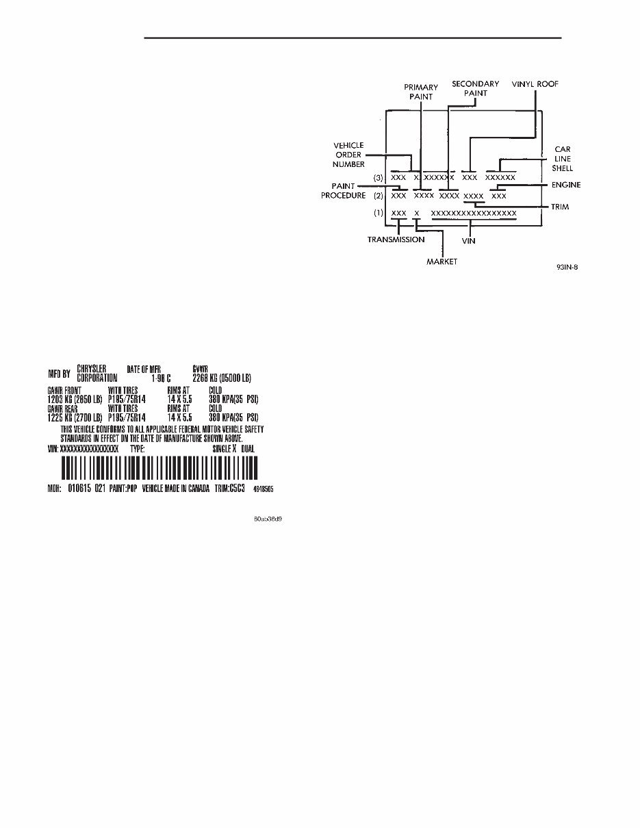
VEHICLE SAFETY CERTIFICATION LABEL
A vehicle safety certification label (Fig. 1)is
attached to every Chrysler Corporation vehicle. The
label certifies that the vehicle conforms to all appli-
cable Federal Motor Vehicle Safety Standards. The
label also lists:
• Month and year of vehicle manufacture.
• Gross Vehicle Weight Rating (GVWR). The gross
front and rear axle weight ratings (GAWR’s) are
based on a minimum rim size and maximum cold tire
inflation pressure.
• Vehicle Identification Number (VIN).
• Type of vehicle.
• Type of rear wheels.
• Bar code.
• Month, Day and Hour (MDH) of final assembly.
• Paint and Trim codes.
• Country of origin.
The label is located on the driver-side door shut-
face.
BODY CODE PLATE
LOCATION AND DECODING
A metal body code plate is attached to the left
(driver’s side) of the dash panel in the engine com-
partment. There are seven lines of information on
the body code plate. Lines 4, 5, 6, and 7 are not used
to define service information. Information reads from
left to right, starting with line 3 in the center of the
plate to line 1 at the bottom of the plate (Fig. 2).
The last code imprinted on a vehicle code plate will
be followed by the imprinted word END. When two
vehicle code plates are required, the last available
spaces on the first plate will be imprinted with the
letters CTD (for continued).
When a second vehicle code plate is necessary, the
first four spaces on each row will not be used because
of the plate overlap.
BODY CODE PLATE—LINE 3
DIGITS 1 THROUGH 12
Vehicle Order Number
DIGITS 13, 14, AND 15
Open Space
DIGITS 16, 17, AND 18
Car Line Shell
• XJT = Cherokee 2WD (LHD)
• XJJ = Cherokee 4WD (LHD)
• XJB = Cherokee 2WD (RHD)
• XJU = Cherokee 4WD (RHD)
DIGIT 19
Price Class
• L = Cherokee (All)
DIGITS 20 AND 21
Body Type
• 72 = 2–Door
• 74 = 4–Door
BODY CODE PLATE—LINE 2
DIGITS 1,2, AND 3
Paint Procedure
DIGIT 4
Open Space
DIGITS 5 THROUGH 8
Primary Paint
Refer to Group 23, Body for color codes.
DIGIT 9
Open Space
Fig. 1 Vehicle Safety Certification Label—Typical
Fig. 2 Body Code Plate Decoding
2 INTRODUCTION XJ
GENERAL INFORMATION (Continued)
DIGITS 10 THROUGH 13
Secondary Paint
DIGIT 14
Open Space
DIGITS 15 THROUGH 18
Interior Trim Code
DIGIT 19
Open Space
DIGITS 20, 21, AND 22
Engine Code
• EPE = 2.5 L 4 cyl. MPI Gasoline
• ERH = 4.0L 6 cyl. MPI Gasoline
BODY CODE PLATE—LINE 1
DIGITS 1, 2, AND 3
Transmission Codes
• DDQ = AX5 5–speed Manual
• DGS = AW4 4–speed Automatic
DIGIT 4
Open Space
DIGIT 5
Market Code
• B = International
• C = Canada
• M = Mexico
• U = United States
DIGIT 6
Open Space
DIGITS 7 THROUGH 23
Vehicle Identification Number (VIN)
Refer to Vehicle Identification Number (VIN) para-
graph for proper breakdown of VIN code.
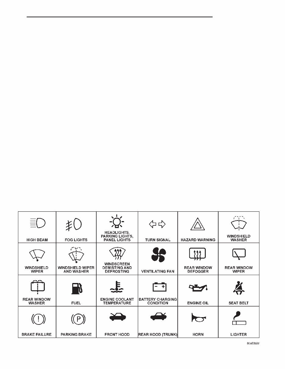
INTERNATIONAL VEHICLE CONTROL AND
DISPLAY SYMBOLS
INTERNATIONAL VEHICLE CONTROL AND
DISPLAY SYMBOLS
The graphic symbols illustrated in the following
International Control and Display Symbols chart are
used to identify various instrument controls. The
symbols correspond to the controls and displays that
are located on the instrument panel.
INTERNATIONAL CONTROL AND DISPLAY SYMBOLS
Fig. 3
XJ INTRODUCTION 3
GENERAL INFORMATION (Continued)
FASTENER IDENTIFICATION
FASTENER IDENTIFICATION
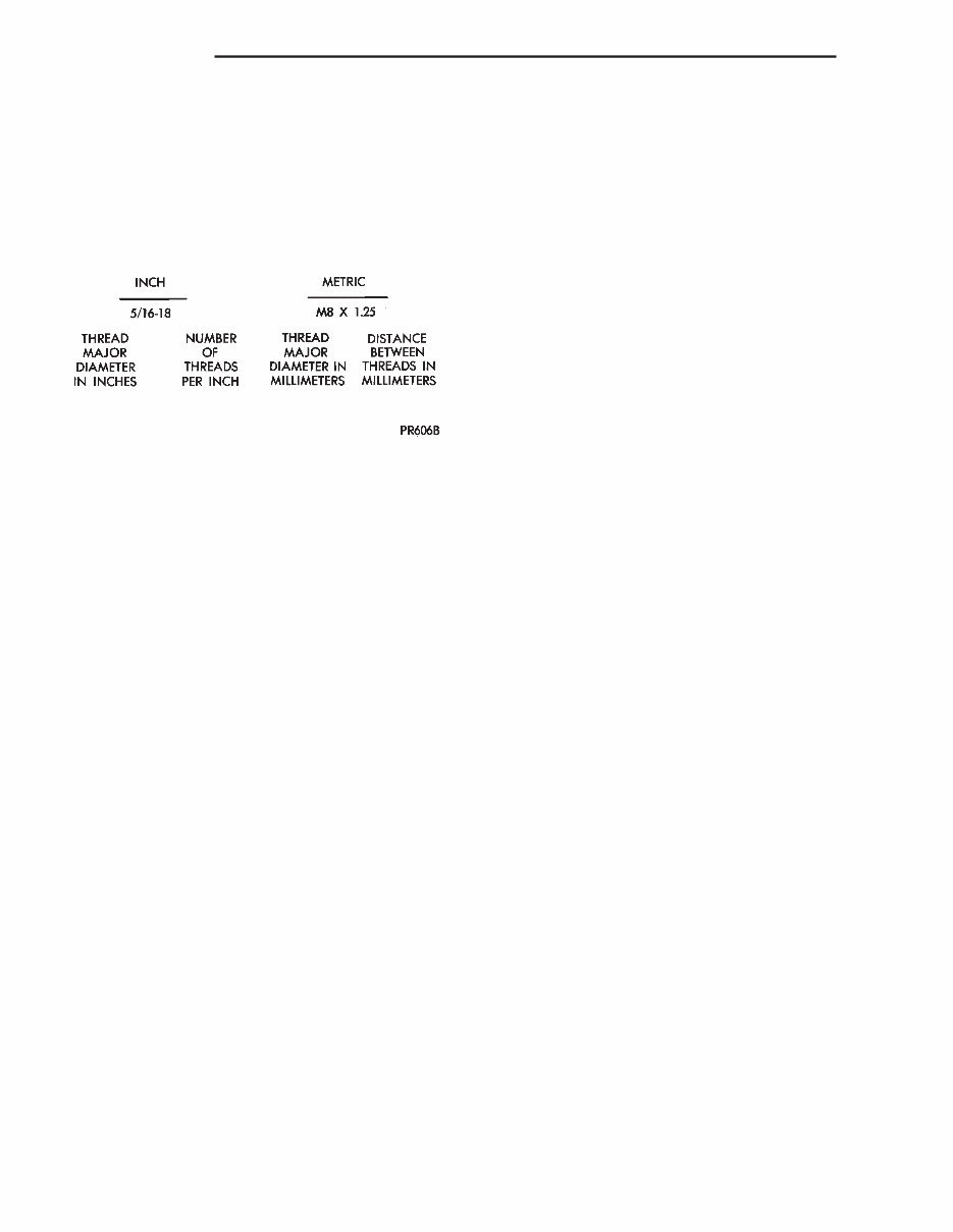
THREAD IDENTIFICATION
SAE and metric bolt/nut threads are not the same.
The difference is described in the Thread Notation
chart (Fig. 4).
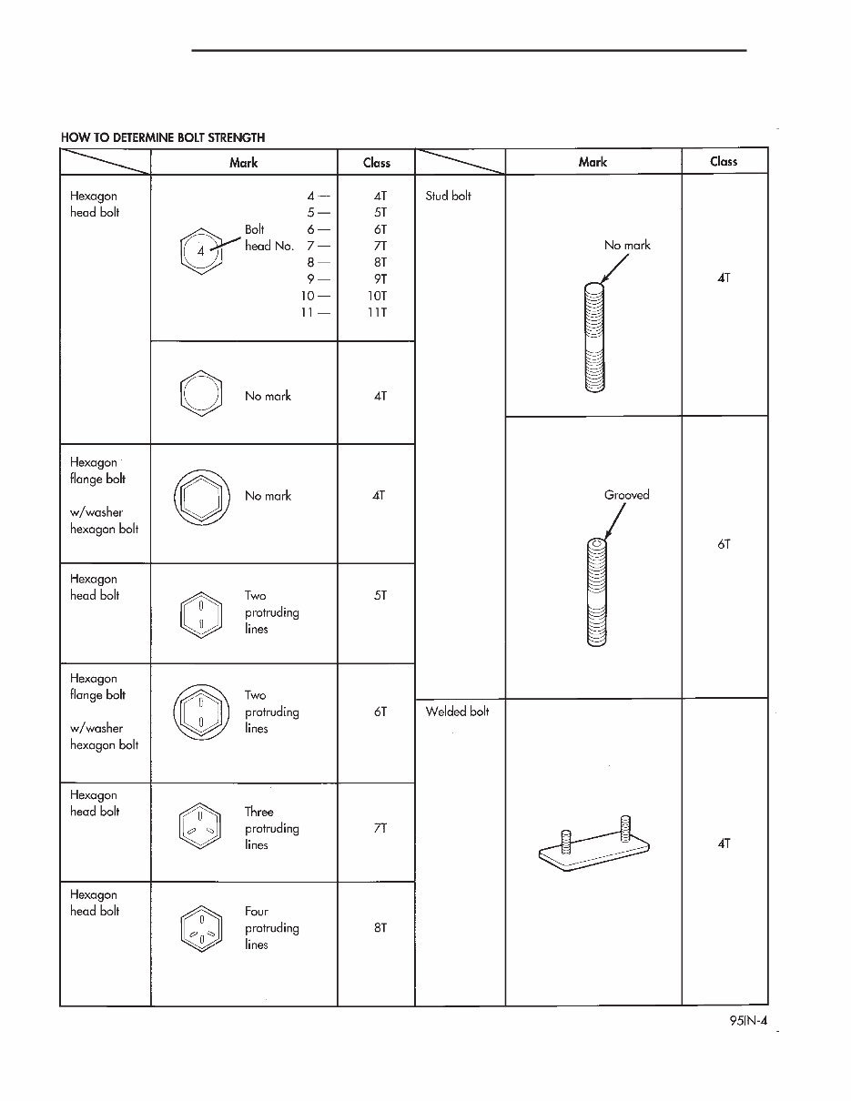
GRADE/CLASS IDENTIFICATION
The SAE bolt strength grades range from grade 2
to grade 8. The higher the grade number, the greater
the bolt strength. Identification is determined by the
line marks on the top of each bolt head. The actual
bolt strength grade corresponds to the number of line
marks plus 2. The most commonly used metric bolt
strength classes are 9.8 and 12.9. The metric
strength class identification number is imprinted on
the head of the bolt. The higher the class number,
the greater the bolt strength. Some metric nuts are
imprinted with a single-digit strength class on the
nut face. Refer to the Fastener Identification and
Fastener Strength Charts.
Fig. 4 Thread Notation Chart – SAE and Metric
4 INTRODUCTION XJ
GENERAL INFORMATION (Continued)
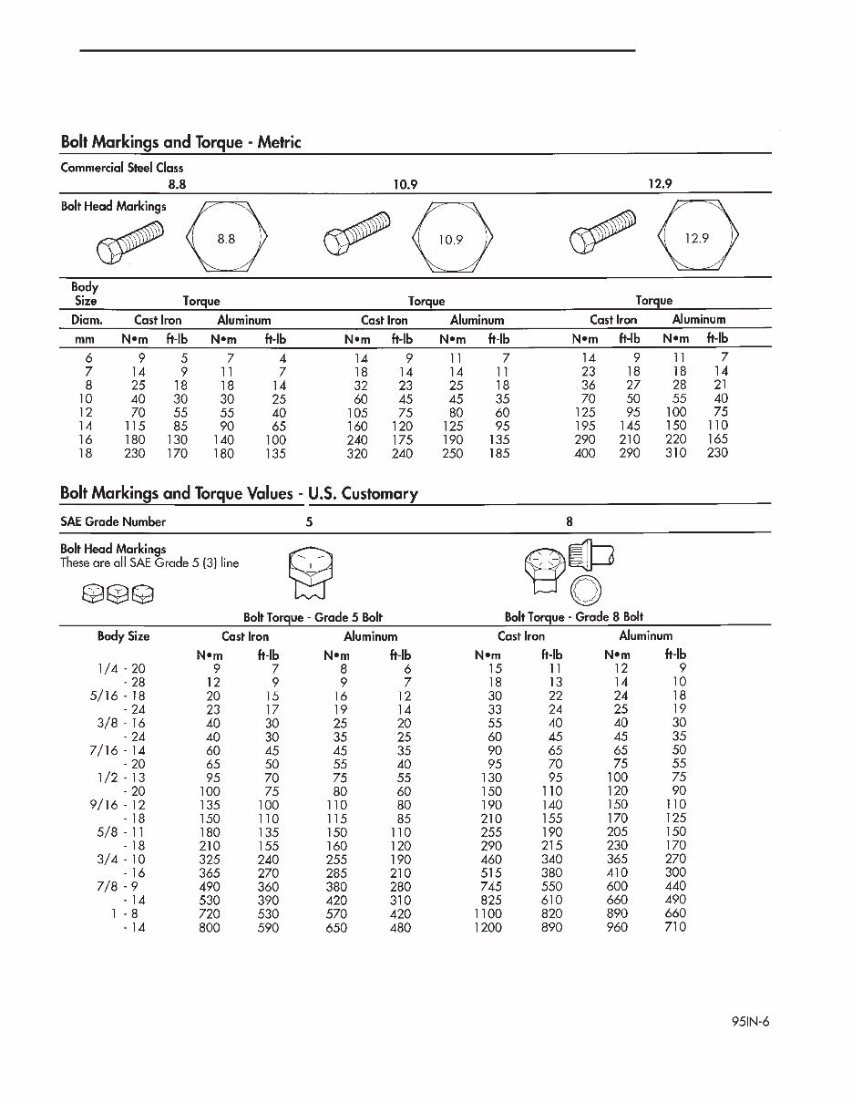
FASTENER IDENTIFICATION
XJ INTRODUCTION 5
GENERAL INFORMATION (Continued)
FASTENER STRENGTH
6 INTRODUCTION XJ
GENERAL INFORMATION (Continued)
FASTENER USAGE
WARNING: USE OF AN INCORRECT FASTENER
MAY RESULT IN COMPONENT DAMAGE OR PER-
SONAL INJURY.
Figure art, specifications and torque references in
this Service Manual are identified in metric and SAE
format.
During any maintenance or repair procedures, it is
important to salvage all fasteners (nuts, bolts, etc.)
for reassembly. If the fastener is not salvageable, a
fastener of equivalent specification must be used.
THREADED HOLE REPAIR
Most stripped threaded holes can be repaired using
a Helicoilt. Follow the manufactures recommenda-
tions for application and repair procedures.
METRIC SYSTEM
WARNING: USE OF AN INCORRECT FASTENER
MAY RESULT IN COMPONENT DAMAGE OR PER-
SONAL IJURY.
Figure art, specifications and torque references in
this Service Manual are identified in metric and SAE
format.
During any maintenance or repair procedures, it is
important to salvage metric fasteners (nuts, bolts,
etc.) for reassembly. If the fastener is not salvage-
able, a fastener of equivalent specification should be
used.
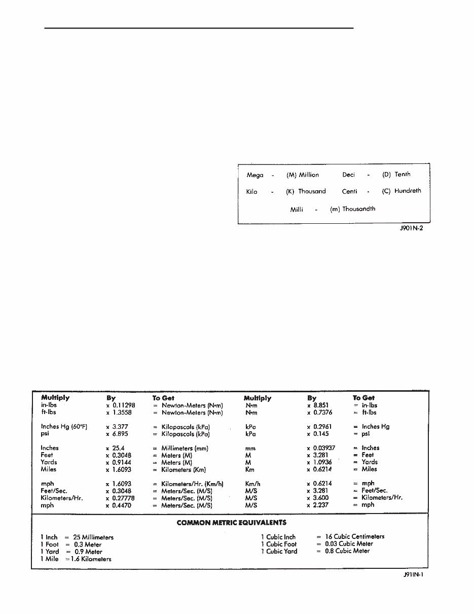
The metric system is based on quantities of one,
ten, one hundred, one thousand and one million
(Fig. 5).
The following chart will assist in converting metric
units to equivalent English and SAE units, or vise
versa.
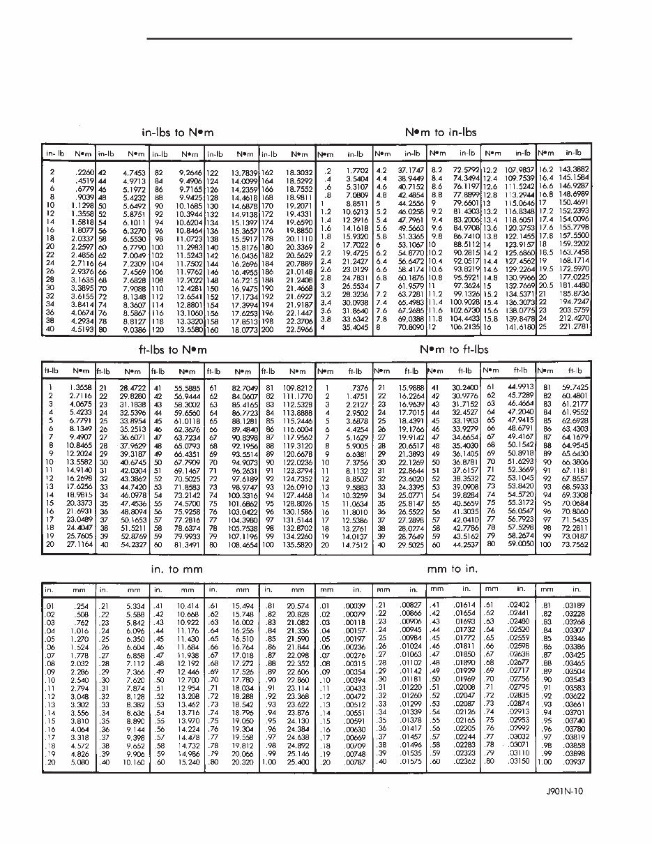
Refer to the Conversion Chart to convert torque
values listed in metric Newton- meters (N·m). Also,
use the chart to convert between millimeters (mm)
and inches (in.)
CONVERSION FORMULAS AND EQUIVALENT VALUES
Fig. 5 Metric Prefixes
XJ INTRODUCTION 7
GENERAL INFORMATION (Continued)
METRIC CONVERSION
8 INTRODUCTION XJ
GENERAL INFORMATION (Continued)
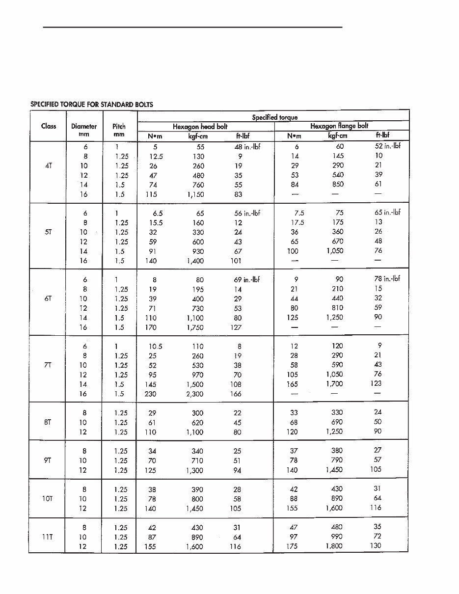
TORQUE REFERENCES
Individual Torque Charts appear at the end of
many Groups. Refer to the Standard Torque Specifi-
cations Chart for torque references not listed in the
individual torque charts.
TORQUE SPECIFICATIONS
XJ INTRODUCTION 9
GENERAL INFORMATION (Continued)
You're Reading a Preview
What's Included?
Fast Download Speeds
Online & Offline Access
Access PDF Contents & Bookmarks
Full Search Facility
Print one or all pages of your manual
$28.99
1999 Jeep Cherokee Service & Repair Manual
Viewed 13 Times Today

What's Included?
Fast Download Speeds
Online & Offline Access
Access PDF Contents & Bookmarks
Full Search Facility
Print one or all pages of your manual
$28.99

Secure transaction
What's Included?
Fast Download Speeds
Online & Offline Access
Access PDF Contents & Bookmarks
Full Search Facility
Print one or all pages of your manual
Description
The Jeep Cherokee 1999 Factory Workshop Repair Service Manual is a comprehensive guide that provides detailed information on maintaining and repairing your Jeep Cherokee. Designed specifically for the 1999 model, this manual is a valuable resource for owners and mechanics alike.
Key features include:
- Step-by-step instructions for all repair and maintenance procedures
- Illustrated diagrams and pictures to aid in understanding
- Diagnostic codes and troubleshooting information
- Specifications and technical data
- Exploded views and parts lists
Whether you're a seasoned mechanic or a Jeep Cherokee owner looking to save on repair costs, this workshop manual is an essential tool. With its easy-to-follow instructions and comprehensive information, you'll be able to confidently tackle any repair or maintenance task on your 1999 Jeep Cherokee.


