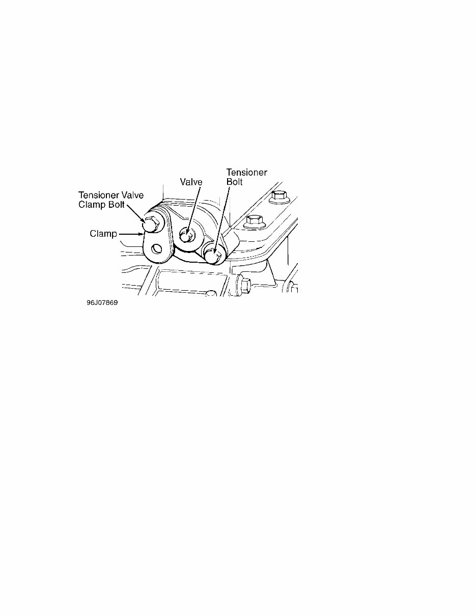
4.0L 6-CYL VIN [7] Article Text (p. 2) 1995 August, 1995. 2) If adjustment is necessary, rotate crankshaft until No. 1 piston is at TDC. Ensure pointer on front timing cover aligns with arrow on timing ring. Using Timing Gauge (18G 1433), ensure camshafts are at TDC. Remove tensioner valve clamp bolt, and swing clamp away from center of chain tensioner. See Fig. 1. Fig. 1: View Of Camshaft Upper Timing Chain Tensioner Courtesy of Jaguar Cars Inc. 3) Remove valve from center of tensioner. Insert a 3-mm Allen wrench into center of tensioner. Turn Allen wrench clockwise until tensioner is in fully relieved position. Remove remaining chain tensioner bolt. Remove chain tensioner, "O" ring and gasket. CAUTION: DO NOT rotate crankshaft while camshaft sprocket is disconnected from camshaft. Serious damage to valve train components may occur. 4) Rotate crankshaft until timing notches in camshaft flanges are pointing down. Remove 2 accessible camshaft sprocket mounting bolts (per camshaft) and lock tabs. Rotate crankshaft until Timing Gauge (18G 1433) can be inserted into slot of camshaft front flange. Remove remaining camshaft sprocket mounting bolts and lock tabs from camshafts. Remove camshaft sprockets from camshafts. 5) Counting from front, remove cylinder head bolt from No. 2 intake camshaft bearing cap. Remove remaining bolts from No. 2 bearing cap. Remove bearing cap, and install Spacer (18G 1435) to cylinder head. Spacer is used to keep cylinder head from moving. Reinstall cylinder head bolt, and tighten it to 39 ft. lbs. (53 N.m). Repeat step 5) for No. 3-6 bearing caps. 6) Remove cylinder head bolt from No. 7 bearing cap. Alternating between No. 1 and 7 bearing caps, remove remaining bolts and bearing caps. Remove intake camshaft. Install spacer and No. 7 cylinder head bolt. Tighten bolt to 39 ft. lbs. (53 N.m). Repeat steps 5) and 6) for exhaust camshaft. 7) Note cam follower location for installation reference.
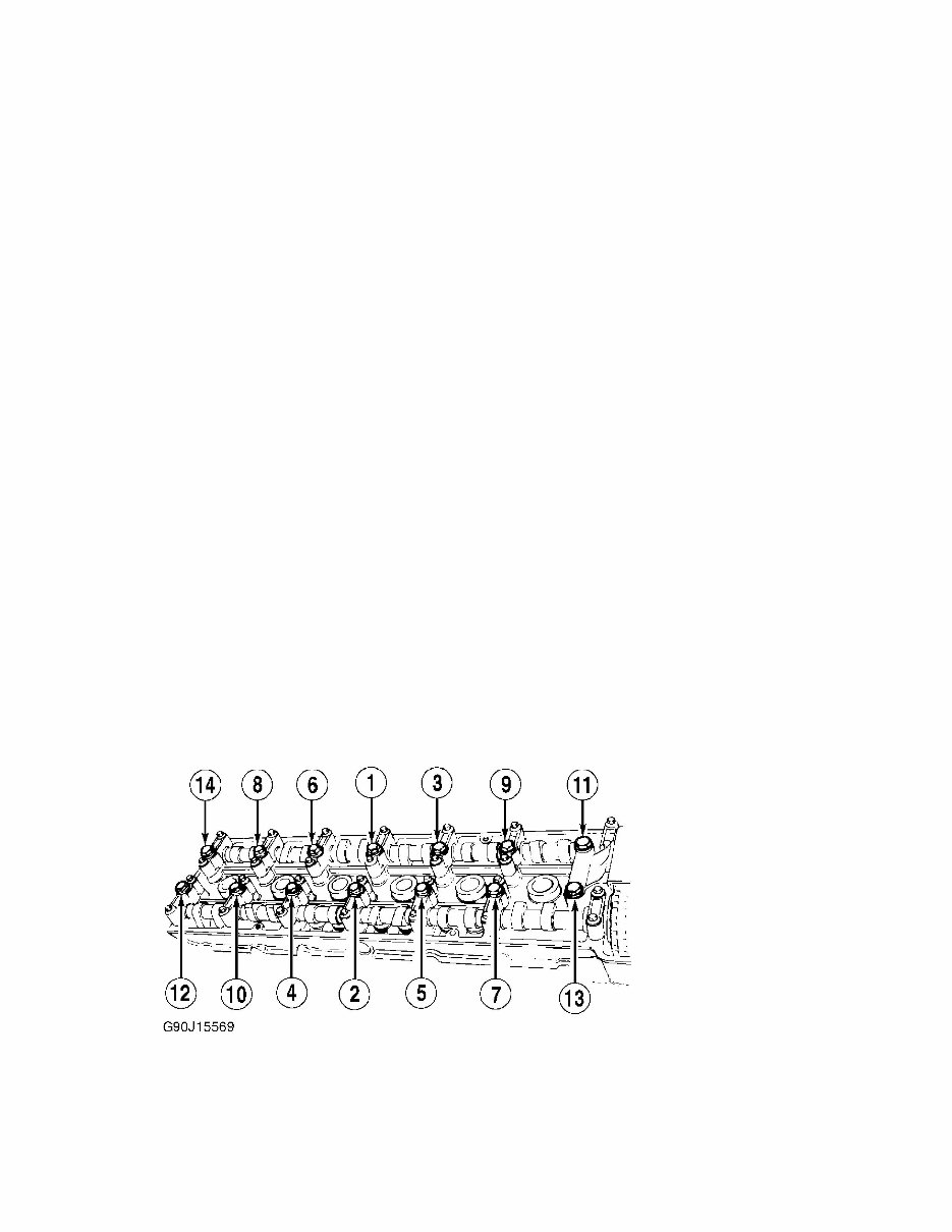
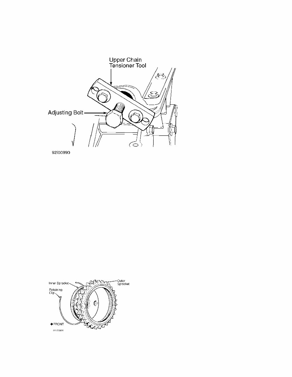
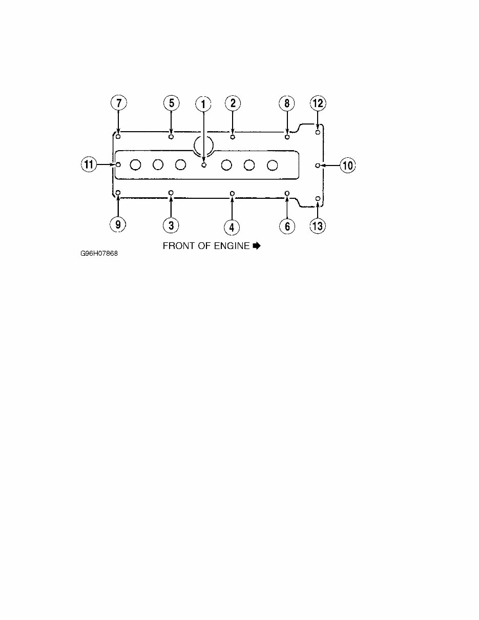
4.0L 6-CYL VIN [7] Article Text (p. 3) 1995 Jaguar XJ Remove cam follower from valve requiring adjustment. Remove adjusting pad, and measure its thickness. Use adjusting pad's measured thickness and difference between valve's measured clearance and specified clearance to calculate required thickness of NEW adjusting pad. NOTE: Always return cam followers to their original position. 8) Adjusting pads are available in .001" (.03 mm) increments, ranging from .085" (2.16) to .108" (2.74 mm), and are marked with letters from "A" to "Z" respectively. Insert correct adjusting pads, and install cam followers. Ensure No. 1 piston is at TDC. Install intake camshaft, and align it with timing gauge. CAUTION: Always use NEW cylinder head bolts. 9) Lubricate cam bearing caps with clean engine oil. Install No. 1 bearing cap. Remove No. 7 cap cylinder head bolt and spacer. Install No. 7 bearing cap. Alternately tighten No. 1 and 7 bearing caps. Remove spacers from cylinder head in following order: No. 4, 2, 3, 5 and 6. After one spacer is removed, immediately install camshaft bearing cap before removing next spacer. 10) Ensure intake camshaft is still at TDC. Install exhaust camshaft, and align it with timing gauge. Repeat step 9) for exhaust camshaft bearings. Tighten NEW cylinder head bolts in sequence to 43- 45 ft. lbs. (59-61 N.m), then turn bolt an additional 90 degrees. See Fig. 2. 11) Fit camshaft sprockets onto camshafts. Move all slack in timing chain to tensioner side. Install Upper Chain Tensioner Tool (18G 1436). See Fig. 3. Tighten center bolt on tensioner tool to tension upper chain. Fig. 2: Cylinder Head Tightening Sequence Courtesy of Jaguar Cars Inc.
4.0L 6-CYL VIN [7] Article Text (p. 6) 1995 Jaguar X manifold. Disconnect exhaust pipes from exhaust manifold. Disconnect shift cable from transmission. Position floor jack underneath transmission. Mark drive shaft flanges for installation reference. Disconnect drive shaft from transmission. 5) Remove transmission rear mount. Lower front of vehicle. Remove crankshaft pulley and damper. Discharge A/C system. Remove A/C condenser. Disconnect hoses from A/C compressor. Remove engine bracket-to-front engine mount nuts. 6) Check for wires, hoses or any other components that are still attached. Being careful not to damage steering rack, lift and remove engine/transmission assembly from engine bay. Remove transmission from engine. Installation Carefully lower engine/transmission assembly into position, and tighten front engine mounts. Reverse removal procedure to complete installation. Check all fluid levels. Evacuate and recharge A/C system. INTAKE MANIFOLD Removal 1) Disconnect negative battery cable. Drain cooling system. Remove air cleaner assembly. Remove engine oil dipstick tube retaining bolt. Disconnect hoses from intake throttle elbow. Disconnect cam cover breather hose. Remove oil filler tube from lower housing. Disconnect throttle cable. 2) Disconnect heater hose from cylinder head. Remove intake manifold bolts and nuts. Disconnect ground wire from front stud. Remove engine wiring harness from intake studs. Remove oil filler tube upper mounting bracket. 3) Check for wires, hoses or any other components that are still attached. Carefully remove intake manifold and gaskets from cylinder head. Installation Clean gasket mating surfaces. Install NEW intake manifold gaskets. Install intake manifold, and tighten nuts to specification. See TORQUE SPECIFICATIONS. EXHAUST MANIFOLDS Removal Raise and support vehicle. Disconnect oxygen sensor connector. Disconnect exhaust downpipes from manifolds. Remove heat shield. Remove front and rear exhaust manifolds and gaskets. Installation Clean gasket mating surfaces. Install NEW exhaust manifold gaskets. Install exhaust manifolds. Tighten nuts to specification. See TORQUE SPECIFICATIONS. To complete installation, reverse removal procedure.
4.0L 6-CYL VIN [7] Article Text (p. 8) 1995 Ja ensure camshafts are still at TDC. Ensure No. 1 piston is still at TDC. Install cylinder head. Tighten NEW cylinder head bolts in sequence to 45 ft. lbs. (61 N.m), then turn bolt an additional 90 degrees. See Fig. 2. 2) Position wiring harness clip and hose bracket, and install front cylinder head bolts. Fit camshaft sprockets onto camshafts with slack in timing chain on tensioner side of chain. DO NOT rotate crankshaft or camshaft to position slack in timing chain on tensioner side. Install Upper Chain Tensioner Tool (18G 1436). See Fig. 3. Tighten center bolt on tensioner tool to tension upper chain. 3) Remove inner sprocket retaining clip. See Fig. 4. Remove inner sprocket, and align sprocket holes with holes in camshaft. Reinstall inner sprocket. Install lock tabs and retaining bolts. Install inner sprocket retaining clip. 4) Remove tensioner tool. Clean tensioner gasket mating surfaces. Install NEW tensioner gasket. Lubricate and install NEW "O" ring on tensioner. Install tensioner assembly into cylinder head. Tighten lower tensioner retaining bolt. DO NOT tighten valve clamp bolt at this time. 5) Clean tensioner valve assembly, and install NEW "O" rings. Insert 3-mm Allen wrench into center of tensioner. Turn Allen wrench counterclockwise to release tensioner. Lubricate and install tensioner valve. 6) Position tensioner clamp over tensioner valve. Tighten tensioner clamp bolt. Using NEW gasket, install cam cover. Install coil cover and coils to spark plugs. Install cam cover breather hose. To complete installation, reverse removal procedure. FRONT COVER Removal 1) Disconnect negative battery cable. Remove hood. Remove intake manifold. See INTAKE MANIFOLD. Remove cylinder head. See CYLINDER HEAD. Remove fan clutch and radiator fan shroud. 2) Remove oil pan-to-front cover bolts. Remove power steering pump. Remove plastic power steering pump drive coupling. Remove bolt securing power steering drive plate. Using pry bar, remove power steering drive plate from auxiliary shaft. Remove alternator belt. Remove crankshaft damper. 3) Remove crankshaft speed sensor, and set aside. Disconnect coolant hoses from water pump. Remove water pump. Remove alternator adjusting bolt from front cover. Remove front cover retaining bolts and cover. Remove crankshaft Woodruff key and spacer. Remove front cover oil seal. Installation Clean gasket mating surfaces. Install NEW front cover oil seal. Ensure seal is flush with cover. Apply Hylosil 102 sealant to front cover gasket area and outer edge of oil pan. Install front cover. Using NEW "O" ring, install crankshaft spacer and Woodruff key. To complete installation, reverse removal procedure.
Get the comprehensive 1995 Jaguar XJS Service & Repair Manual for all models. This digital manual provides essential information including detailed repair and maintenance procedures, accurate part layouts, wiring schematics, and precise part numbers—all tailored specifically for the 1995 Jaguar XJS. Enjoy the convenience of printing the pages you need, whenever you need them, without the hassle of bulky paper manuals.
This manual is an invaluable resource whether you are a professional mechanic, a DIY enthusiast, or a Jaguar owner looking to save on repair costs. Even with limited repair experience, you can confidently take on minor repairs, while also researching major repair procedures in advance to ensure you are well-informed before visiting a mechanic. Experienced users will appreciate the in-depth technical details provided for extensive repairs.
Over 70 separate sections covering various components and systems
Clear repair and maintenance procedures
Accurate wiring schematics and part layouts
Precise part numbers specific to the 1995 Jaguar XJS