Powertrain Automatic Transmissions Service Manual CON TENTS Section Title SRO Page Foreword ........................................................................... ii I ................ Service Tools & Equipment ........................................................... iii I1 ................ Torque Tightening Specifications ....................................................... iii 111 ............... Service Materials .................................................................... iii IV ............... Service Data ....................................................................... iii 1.1 .............. General Description .................................................................. 1 7.1.1 ............. Gear Range ......................................................................... 1 1.1.2 ............. lubrication Circuits .................................................................. 3 1.1.3 ............. CoolerCircuit ....................................................................... 3 1.2 .............. Transmission Components ............................................................. 5 1.2.1 ............. Torqueconverter .................................................................... 5 1.2.2. ............ Planetarv Gear Sets ................................................................... 5 1.2.3 ............. Torque Converter Clutch .............................................................. 5 1.2.4 ............. Pulse Width Modulated (PWM) Solenoid ................................................. 6 1.2.5 ............. Input And Output Speed Sensors (TISS)And (TOSS) ........................................ 6 1.2.6 ............. Shift Solenoids ‘A’ And ‘6’ ............................................................. 6 1.2.7 ............. Variable Force Solenoid/Motor (VFS) ................................................... 6 1.2.8 ............. Transmission Control Module (TCM) .................................................... 6 1.2.9 ............. Pressure Switch Manifold (PSM) ........................................................ 6 1.2.10. ........... Transmission Temperature Sensor ....................................................... 6 1.2.11 ............ Accumulators ....................................................................... 6 1.3 .............. Oil Pump And Internal Valves .......................................................... 7 1.3.1 ............. Pressure Regulator Valve Train ......................................................... 7 1.3.2 ............. Reverse Boost Valve .................................................................. 7 1.3.3 ............. Torque Converter Clutch Enable Valve ................................................... 7 1.3.4 ............. Torque Converter Clutch Shift Valve ..................................................... 7 1.3.5 ............. Converter Limiting Valve .............................................................. 7 1.4 .............. Valves In Valve Body ................................................................. 8 1.4.1 ............. Torque Signal Compensatory Valve ..................................................... 8 1.4.2 ............. Checkball Valves ..................................................................... 8 1.4.3 ............. Active Components For Each Gear Ratio ................................................ 10 1.5 .............. Hydraulic Circuit Diagrams ........................................................... 11 1.6 .............. Fault Diagnosis ..................................................................... 24 1.6.1 ............. Initialchecks ....................................................................... 24 1.6.2 ............. Engine Tune ........................................................................ 24 1.6.3 ............. Stall Test ........................................................................... 24 1.6.4 ............. Road Test .......................................................................... 24 1.6.5 ............. Electrical Checks .................................................................... 24 1.6.6 ............. Transmission Fault Codes ............................................................. 25 1.7 .............. Service Operations .................................................................. 26 1.7.1 ............ Rear Servo Assembly - Renew (6.OL) .............................. 44.34.13 ............ 26 1.7.2 ............. Front Servo Assembly - Renew (4.0 liter SC and V12) ............... 44.34.17 ............ 27 Remove For Access and Refit (4.0 liter SC and V12) ................. 44.40.05/90 ........ 28 . 7.3 ............ Valve Body And Accumulator - . 7.4 ............ Valve Body Assembly- Renew (4.0 liter SCand V12) ................ 44.40.06 ............ 29 Issue 1 August 1994 i
Powertrain Automatic Transmissions Service Manual 0 FORE WORD This manual provides information relevant to the servicing of Automatic Transmission Units 4L8Ck-E (irrespective of the vehicle range to which the unit isfitted). The manual should be used in conjunction with the relevant Vehicle Service Manual (VSM) and Electrical Diagnostic Manual (EDM). It assumes that the transmission has been removed from the vehicle, in accordance with the Vehicle Service Manual, and is in a clean condition and all service tools and materials are available. The manual is divided into sections covering: 0 Sub-section 0 - service information 0 Sub-section 1 - detailed mechanical description 0 Sub-section 2 - general data (service-relevant) 0 Sub-section 3 - hydraulic circuit diagrams 0 Sub-section 4 - troubleshooting 0 Sub-section 5 - service repair operations. An index can be found at the rear of the manual. Note: For information relating to in-vehicle operations, refer to the Vehicle Service Manual. issue 1 August 1994 ii
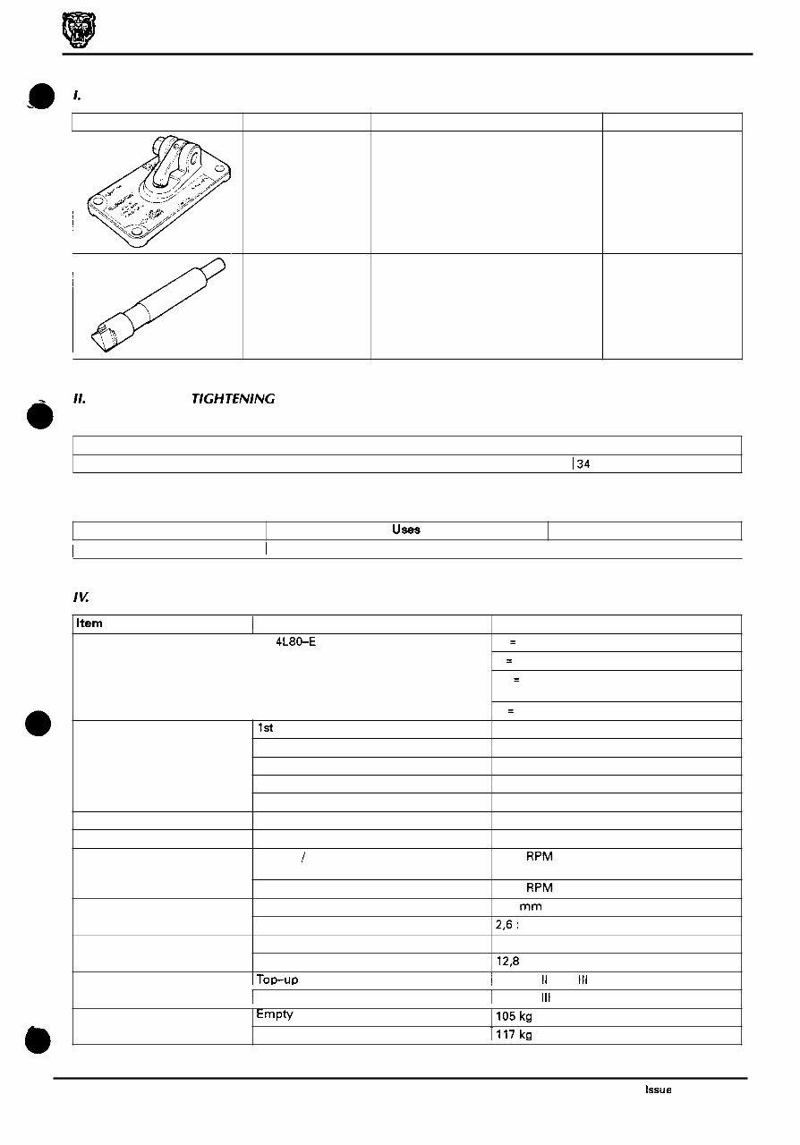
Powertrain Automatic Transmissions Service Manual Illustration Jaguar Number JD 192 JD 193 Description Notes Pin checking tool Stepped gauge pin 11. TORQUE TlGH TENING SPECIFICATIONS Nut on checking tool JD 192 I34 Description UseS Notes I To be issued I I I Item I Description Explanation of model designation 4L80-E Gear ratios 1st 2nd 3rd 4th Reverse Maximum torque (into the converter) Maximum torque (at the turbine shaft) 4 liter s / c 6.0 liter Stall torque ratio Drain and refill only Complete fill Engine torque Gearbox torque Maximum shift speed (all upshifts) Torque converter Diameter Transmission fluid capacity IU SERVICE DATA Data 4 = 4 Speed L = Longitudinal mounting 80 = Series (based on relative torque capacity) E = Electronic control 2,482 : 1 1,482 : 1 1,000: 1 0,750: 1 2,077 : 1 597 N m 1200 N m 5500 RPM 6000 RPM 310 mm 2,6: 1 7.3 liter 12,8 liter Transmission weight 1 Dexron II E or 111 Transmission fluid I TOP-UP Empty I105 kg Complete with fluid I117 kg I Fill I Dexron 111 Issue 1 August 1994 iii
The Jaguar X300 XJ Workshop Manual 1995-1997 is a detailed guide tailored for individuals working on Jaguar X300 XJ models manufactured between 1995 and 1997. It is a comprehensive resource covering various models within the X300 XJ range, including the XJ6, XJ12, and XJR.
Whether you are a professional mechanic or a DIY enthusiast, this workshop manual provides all the necessary specifications, diagrams, and step-by-step procedures for diagnosing, repairing, and maintaining your Jaguar X300 XJ. It encompasses a wide range of topics such as the engine, transmission, suspension, and electrical system.
By following the detailed instructions in this workshop manual, you can confidently address a variety of repairs and maintenance tasks, ultimately saving time and money. The manual is structured in a user-friendly manner, facilitating easy navigation through sections to locate specific information.
Acquiring the Jaguar X300 XJ Workshop Manual 1995-1997 is essential for keeping your Jaguar X300 XJ in optimal condition. Whether you are conducting routine maintenance or tackling more complex repairs, this workshop manual is indispensable for any Jaguar X300 XJ owner or mechanic.