1979-1990 Jaguar XJ V6 V12 Series 3 Service & Repair Manual
What's Included?
Lifetime Access
Fast Download Speeds
Online & Offline Access
Access PDF Contents & Bookmarks
Full Search Facility
Print one or all pages of your manual
Containing Sections 01 INTRODUCTION JAGUAR I 'LJ..--r.aimler 04 GENERAL SPECIFICATION DATA 05 ENGINE TUNING DATA 06 TORQUE WRENCH SETTINGS 07 GENERAL FITTING INSTRUCTIONS 08 LIFTING AND TOWING 09 CAPACITIES 10 MAINTENANCE 99 SERVICE TOOLS BOOK 1 SERIES III ~= SERVICE MANUAL ~~ Published by Jaguar Cars Limited __ P yb hC,""On P ;o" ~ ""'b.' S ___ --:-1 S.'~IC. M ~n"'" Com p'.' . -'111'.'9 006 Edm...2 S ..... cc M an ... 1 a oo ~'" AKM 90061,6 £dilion2 Pmled In EngIf,nd Seo., e o. M~" ... I Bonde. AItM9006!1 E <I;' .... 2
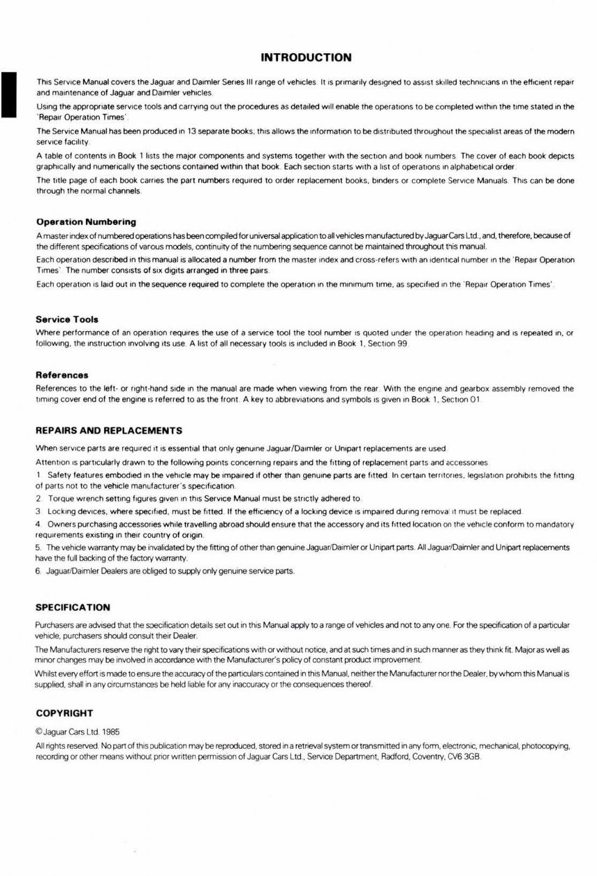
I INTRODUCTION This Servo<:e Manual covers the Jaguar and Daimler SerieS III r ange 01 vehICles 1115 primarily clesogned to assist sk ,Hed techrI!C'3ns on the ef!+coent repa" and mamtenance of Jaguar and Daimler verncles USing the appropriate serv>ce tools and carrYing 00\ the procedUfes as de1alled Will enable the operations to be completed w ,lhon Ulf! time st aled ,n the "Repau Operat lOl1 Times' The ServICe Manual has been produced In 13 separate books. thiS allows the ,nl orma t oon l obe d,w,boled throughout,he specialist areas 01 the modef n $efvoce facility A table of contents ,n Book 1 lists the maIO' components and systems together With the SOCl>oo and book numbef S The cove< 01 each book deptcts gr aptncally and numeflcall y the sectoons contai ned w lth,n thaI book Each SOCtlOf'l Slans With a lis! 01 oper,l1,ons In alphabe tICal order The !,Ue page 01 each book can leS the part numbers required 10 order repiacelTlefl\ books. binders or comp lete Serv.ce Manuals Th,s can be dooe through the normal ch¥1nels Operation Numbering A master Index of numbered operations has been compiled for univefsal application toal vehicles manufactured by JaguarCars Ltd_ , and, therefore, becauseol the diHerent specifICations of varous models, continuity of the roumbering sequence carY'OOt be maintained throughout this manual_ Each opefatlOn described on th iS manual IS allocated a numbef Irom the mastef Inde~ and cross-refers With an IdentICal numbef In lhe 'Repair Operation Times' The numbef ConSists o f Sl~ dlglls arranged In three pairs Each operatIOn IS laid OU I In the sequente required 10 complete lhe opefatlOn In lhe mlnomum t,me. as specified In the ' RepaIJ Operation Times' Service Tool. Where perf ormance of an operatIOn requOJes the use of a servICe tool the tool number IS quoted uf1def the operation heading and IS repeated In, 01 follow ing, the InstrUClIon Involvng Its use A list of all necessary loois IS Included ,n Book 1. SectIOn 99 Reference. References to the lef,- 01 right -hand side In the manual are made when vteWtng from lhe rear W tlh lhe engine and gearbo~ assembly removed the ttmlng cover end 01 the engtne I~ re fef red to as the froot A key to abbrevi atIOnS and symbols IS given on Boc:* 1. St<:tlOf1 01 REPAIRS AND REPLACEMENTS When SefVICe parts are reqUired ''is essentIal thaI only genutne Jaguar /Daimler or Un,part replacements are used AnentlOO IS par\lcularly dra wn to the follOWing poif"Its concefnong repairs and the filling of repl acement pailS and accessones 1 Safety features embodied on the vehICle may be Impall ed If o lher than genuine parts are fll1ed In certain tl:!/fllOIteS. leglslatlOfl prOtlibitS the fllI'ng of pails not to the vehICle manufacturer's specificatIOn 2 Torque w rench sel1lng f ogures given In thiS Ser vICe Manual mus t be strICtly adhered to 3 loc king deVICes, where spe<lfled. must be fi lled 11 lhe eHICtency 01 a locking deVICe IS Impaired dUling remova II must be replaced <I Owners purchaSing accesSOIteS wh!le travelling abfoad should ens ..... e Ihat the accessory and lIS hned Ioca\lon on the vehICle con form 10 mandatOlY requir ement s e~ISllng In their country of origin . 5 The vehICle warranty may be invalidated by the fitting 01 olhef than genuine JaguarlDaim~or Unipan parts_ All JaguaiOaimler and Unipan reptacements have the M backing of the factory warranty. 6. JaguarlDaimler Dealers are otliged 10 supprv only genuine service parts. SPECIFICATION Purchasers are advised that the s:Je(:i fication details set out In thi s Manual apply to a range of vehicles and not 10 any one. For the specilica\lon of a particvtar vehicle, purchasers should consult their Dealer_ The ManufactlJrers reserve the ngh! 10 vary their specifications with or without notice, and at such t imes and in such manner as they think I~_ M ajor as well as m,f"OI changes may be involved in accordance With the Manufacturer's polICY of constanl product I mprovernoot . l!Vhilst every effort 's made to ensure the!lCOJracy of the parttculars contai ned in this Manual. neilher the Manufacturer flOr the Dealer. bywhom this Manual is supplied. shan In any cifCUmstances be held liable for aoy inaccuracy or the consequences thereof COPYRIGHT ClJaguarCars Ltd.l965 Al l nghts reserved No part of thiS DUOficatlOl1 may be reproduced. stored in a relrieva1 system or transmined in any form, eectfOfllC, mechanical. photocopying. record ing Of other means Without pnor WI1nen permlSSIOl1 01 Jaguar Cars Ltd .. Servoce Oepanment. Radford, Covenlry, CV6 3GB
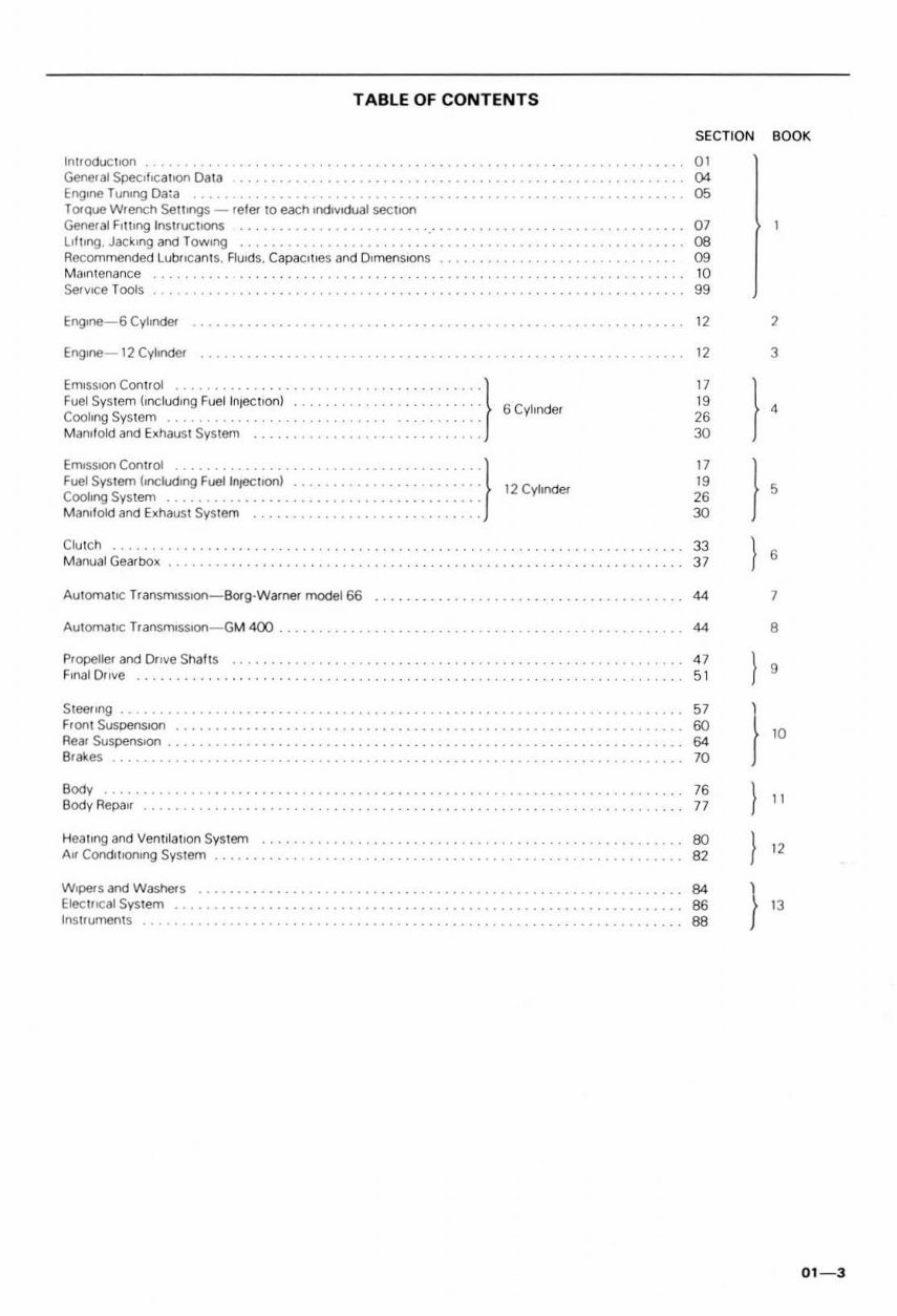
TABLE OF CONTENTS IntroductIon ......... ... ...... . SECTION BOOK 01 General Speci f ica tIOn Dat a ................................ . Engme T unlllg Da: a ..... . .... . ............................ . .............. . Torque Wrench Setllngs - re l er to each Individual section General Filling Instructions ................. _ . ............ . ............. . lifting. Jacking and TOWing ................................ . Recommended Lubflc ants. Fl uid s, CapacIties and DimenSions ........ . M aIn tena nce Service Tools '" 05 07 DB 09 10 99 12 Erog,oe- 12 Cylinder . . . . . . . . . . . ..... 12 EmlSSJOn Con t rOl ............. . Fuel Sy stem hnciudmg Fuel In,echo n) ....... • Cooling System .......... ....... . Manifold and Exhaust System EmlS5IOf1 Con lr ol ........ . Fuel Syst em (Illcludrng Fuel l njOCt l()(1) ....... • COOling System M an, fold and Ex haust System ..... ..... • Clu TCh Manual Gearbox : : : } 6 C" ,"d" : : :} 12 C' '' od" 17 19 26 30 17 19 26 30 33 37 Automa tIC Transmr sslOtl-BOf g-Warner model 66 . .• .. .. ... . ......... 44 Automa tIC TransmlsslOtl- Gt.II 400 .. ............... ................ • ......... •.• .. 44 Propell er and Dri ve Shalts ...................................... . Final Drive ..•.•.•. . ....... . Steeling ........... . Front SusoenslOrl ..... • .. Rear SuspenslOO ...... •... •.•. Blakes ......... . Bod, Bodv Repall Hea l ing and Ventilation System Air CondlllOl"ll ng System .. W,pelsand Wa 5hefs ••.• ....... ..•.• .•. • .... ..... ...•.•. •.•. Elec trICal System ...... . Instruments 47 51 57 6C 64 . ............. 70 76 77 BO B2 B4 B6 B8 , 3 7 8 01 - 3
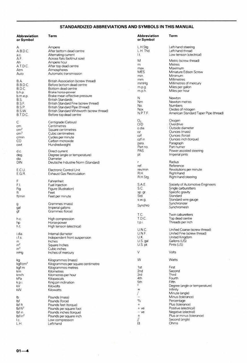
STANDARDIZED ABBREVIATIONS AND SYMBOLS IN THIS MANUAL Abbrevi.tion Term Abbrevi.tion Term or Sym bol or Symbol A Am"", L. H Stg Left-hand steenng ABOC After bo!1oTl dead cer1tre L.H Thd Left-hand thread a.e. Aftema~ng current " Low tenSlOl1(IJectncal) A.' Across Hats ~boftInut sIZe) M MetrIC (screw thread) Ah Ampere hoJr AT DC After top dead centre m MetreS A<m Atmospheres ~. Maxmum Auto AutomatIC transmiSSIOn MES Miniature Edison Screw min. Mlmmum BA 8mash AssoooIlOn (screw thread) mm M~limetreS BBDC Before bonom dead centre mmHg M~hmetres d mercury BDC Bottom dead cer1tre mpg Miles per gal\:ln b.hp Brake~r mph Miles per hour bm. ep. Brake mean effectIVE! pressure N N""~ BS Bnllsh Staodard$ B SJ Bmash Standard Fine (screw thread) Nm Newton meres BSP 8nllsh Staodard Pipe (thread) No Nl)ITlbers B SW Bntish Staodard Whitworth (screw thread) NO' Oxrdesof nitrogen BTDC. Before top dead centre NPTF Arnencan Standard Taper PIpe Ithread) C Cenllgrade (CelsIUs) 0, ""- = CentImetres "'" CNerdrrve om' Square cenllmetres o. dia o...tsode diameter =' Cubic centmetres m o...nces (mass) oimoe Cydes permmute "" o...nces (f0fQ!) CO Carbon mcnoXide m'. o...nces onch( torque) ow< Hundredweight "'. Paragr<tJjl "'n~ Partnumer do Olrect current PAS Power asSiSted steenng '" Degree (angle or temperature) pI Impenal prnts d. Orameter D'N Deutsche Irldustne Norm (Standard) , RadiUS ,,' Reference ECU Electroruc Control UM rev/min RevoIutlOOS per ITlInute EG.R Exhaust Gas RearculallOn RH F\;ght-nand R H Stg Roght-hand slrenng , Fahrenheit Ff Fuel InjectIOn SAE. SocIety of Automouve EflQIneers '0 Figure (illustratoon) S.C. Single carburet\ers h '~I sp. gr. $peafic gravoty hI~n Feet per mnute Sid Standard s. wg. Standard wre gauge g Grammes lmass) S"",,,ro Synchroruzer 9" Impenal gallons Synchromesh ~ Grammes Iforce) TC. T wn caburell ers ho High comp-esSlOn TDC. Top dead centre '" Hot"""""" tp. I. Threads per rnch hI Hogh l enSlOfl ~electncal) U NC. Urified Coarse (screw thread) l dia. Internal doaTleter UN' Urifeel Fi ne (screw thread) 1,1.5 Independent front SUspenSIOn U. K Urwted Klngcbm oe Inches US ,. Gallons (US) oe' Square Inches U.s. pt Pints (US) oe' Cubic Inches .Hg Inches 01 mercury V V"" kg K ilogrammes (mass) W W,,,, kgflcm 1 K liogrammes per square cenllmetre kgl m K ilogrammes metres '>I First km K Ilometres '''' s.ronct ,_ K,lometres per hour "" Th.~ kP, K ilopascals "h Fwnh k p.l. K ing pon ondinatlOn 51h Fifth kV Kilovolts Degree (angle or temperature) kW Kilowans • Infimty I M .... ute (angle) • Pourds (rmss) M~us (toler<J1Ce) ., Pourds (force) % Percentage "1ft Pounds fe€t ~torqoJe) , Plus (tolerance) Ibflfe Pounds pel square foot ,~ Posltrve leloctncal) Ibl In Pounds inches (torque) -~ Negawe lelectnal) Ibffln1 Pounds per square Irch ± Plus or minus ( tolerance) '0 Low oompressoon II Second (angle) LH Left-hand n Ohms 0'-4
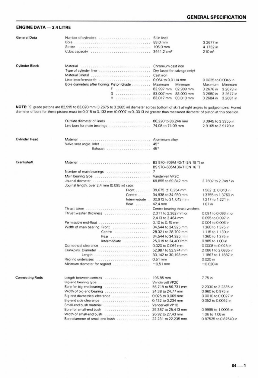
ENGINE DATA-3 .4 LITRE ~.IO'l' Number 0 1cyhnclers Bere ....................... .. ..... . Stroke ............... .•. . ....... . CubIC capacity Cvl;nder 81ocl!. M atellal ........... . T vPIl 01cyll ncler hner .... . Mau~"at (I,ne<SI ............. .. .......... •••• Loner 1fl1efference t 'l ............ ... ......... . BCfe < 1Ia.rneters Ih er honing PI ston Grade .... . f ....... . G H ................ . GENERAL SPECIFICATION 6 hn 1l1'1li) 83,0 nvn 106.0mm 344 1.2 em' Chr omIum caSllJon Dry (used lor salvage only) Cast "on 0, 064 1 00,0 114 mm Maxrmurn Mlfl'mum 82.997 mm 82.989 rnm 83 . 007 mm 83.0')') rnm 83.017mm 83.010mm 32671 on 4 1732 In 210 In' 00025 t o0 0::J4S ,n Ma~omum Mon,mutn 3 2676 on 3 2673 on 32600", 32677", 32684", 3268110 NOTE: 'S' grade postons are 82 .995 to 83 , 020 mm 13 2675 to 3 2685 In) diameter &Cross boHOffl 01 sklr! at n9hl angles 10 gudgeon pons Hone<! d,ameler 01 bore lor lhese postonsmust be 0.018100.133 mm (0 0C1J7 toO. 0013 ,n) Qleate< than measured diameter of Pis ton at thIS pos'toon Cylinder Hel d Conne-ehng Rods Outside diameter of hners llfle bore l or main beaflf'IQs Valve seal angle Inlet E:d 'l30st M atenal Number 01 ma,n bearings ..... . ....... . ...... . Main bearing type ................... . ...... . Journal diameter ............ .. ............. . Journal length. over 2.4 mm (0095 on) radII TtI"ust tal-en TtI"ust washer Ihoct nes.s Wo<I th of mam bear lr"IQ Front o.illTlet"cal clearance CHlnkpons DiarTletef Ler'\g th Regr ono unde<$I1es Centre Rear Intermediate M IlIfI"IUf'r'I lJIarnetef lor regl'lnd Lenglh be tween centres B,,)-end !>ea. ,,,,!) r.,.~ Fron t Cerure . Inte<med,ate ReM BCf e for bog·end beanng ................... . Wo<Ith of bog ·end beanng S,g·end diamelli c al c learance Sog·end side clearance ................ . Small·end bush ma ter..,1 SCfe 1 0< small' erId bush W;dth 01 small' end bu~ 8o"e d_,er 01 small·end bush B6 .220 to 86 .246 mm 74 .08 to 74. 09mm AJurlltlllum alloy 45' .,. 33945 to 3 3955 In 29165 \ 029170,n as 97o-709M 4O/T (E N 19 00< as 97o-605M 36fT (EN 16 TI 1 Vander veil VP2C 69.8551069. 84 2 mm 39.675 ~ 0. 254 mrn 34.938 10 34.950 rom 30.912 to 31. 013 mm 42.4 mm Centre bearong thrusl washers 2.311 to 2.362 mm 0< 2. 4 13102 464 mm 0. 10toO.1 5 mrn 34 .544 1 034.925 mm 28.321 \0 28.702 mm 34.544 1 034.925 mm 25.0191024.400 mm 0.020 \0 0. 064 mm 52.987 to 52.974 rom 30. 142 to 30. 1 93 mm 0.51 mm - 0.51 mm 196. 85 mm VrlncjP.rvell VP2C 56.718 t056.731 mrn 24 .38 to 24.77 mm 0.025 10 0.069 mm 0. 132 1 00.2 34 mm VandervellVP 10 25.387 to 25.4 13 mm 26.921027 .43 rom 22.231 to 22.235 mrn 2 7502 to 2 749 7 In 1562:t 00 100n 13755 10 137600n 1217 1 0122 1 0n 1 67 on 0 091 \0 0093""0< 0095 to0097 on o (X)4 to 0 ())6 ,n 1360 to 1375,n 1 115101130,n 1 360 to 1 375 ,n o 985 to 1 00 on o 0C08 to 0 025 on 2086 1\ 020665,., 1 1867 \0 1 1887,., 0020,n - 0020 on 7 750n 2 2330 to 2 2335 ,n 0900 , 00 975 ,n 000 10 to 0 0027 In 0052 toOm2 ,n o 9995 to I ()))5 on l06tOl08on 0 87525 1 00 8 7540 on 04 - 1
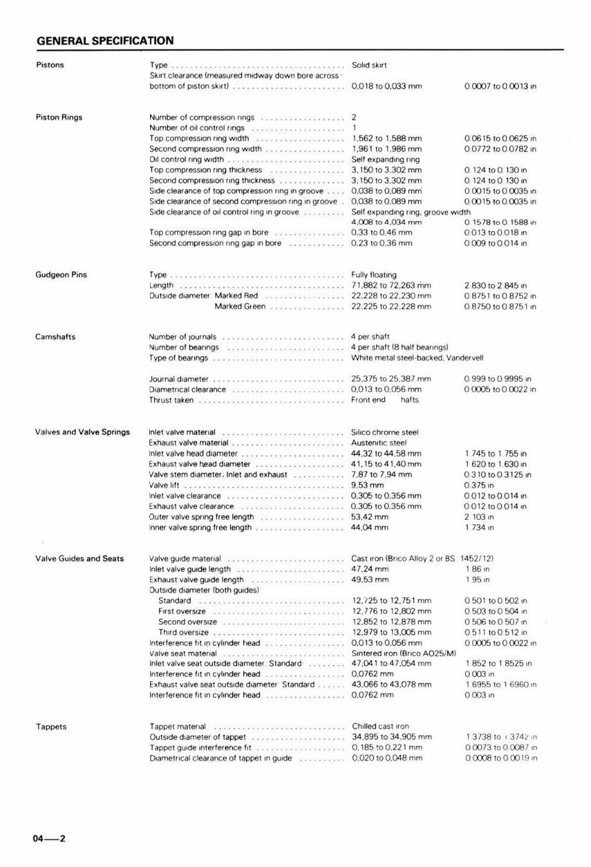
GENERAL SPECIFICATION Pis tons Type . Solid sk'lI SkIrt clearance lmeasured mIdway down bore aclOSS bonomof p,slon sk"l ) . . 0.018 1 00.033 mm 0 (0)71000013111 P,swn Ring s GudgllOn Pins Camshaits Valves and Valve Springs Valve GUIde s and Seats Tappets 04 - 2 Numbel Of compressIon rIngs Numbe< 01 001 ContlQj lingS Top compressIOn (lng w ldlh Se<:ond compr essIOn rIng w Idth . 011 COn1rQj rlng w ldlh . Top compressIon (lng IhlCkness Se<:ond compressIOn ling IhlCkness Side clearance of l OP CompresSIOn r'ng In groove .... Side clearance 01 second compressIon rIng In groove Side clearance of 001 conl rQj lIng In groove Top compressIOn lIng gap In bore Second compressIon ling gap rn bore r"" . Leng lh OulSIde d,amelet Marked Red Marked Gleen Number of pumals Number of bearIngs Type of beallngs Journal dlameler O,ametocal clearance ThruSI taken Inlel valve maletlal .. E~hausl valve malerH"lI ....... . ........... .... . Inlel valve head dlametef E~haust valve l'ead dlameler Valve stem dlametef . Inlet and e~haust Valve lI lt I nlel valve clear ance E~ hausl valve clearance OUler valve SprIng free length I nner' valve SprIng Iree lenglh ....... • Valve guide matellal Inlel valve guide length E~haust valve gUIde length ... .. ... . OU tSIde d,ameter lboth gUIdes) Standard F"st overSIze Second oversIze Tn"d oversI ze .... . ... . Inleflerence 1,1 In cylinder head Valve seal mal ellal In lel valve seal out SIde d ,amelef Standard In l erference "I In cyhnder head Exhaus l valve seat oulslde dlameler Slanc!ard . In lerlerence "I In cylinder head Tappel maler,al OUISKle dlamel er ollappel Tappel gUIde In lerlefence III O,amellK;al clear ance of lapPelln gwde 2 1.562101.588mm 1.961 to l.g86mm Self expandIng ling 3. 15010 3.302 mm 3.150103.302mm 0.038100.009 mm · 0.038 10 0.009 mm 00615 1 000625,n 00772 to 0 0782 In o 124 toO 130 In o 124100 130ln 0 00151000035,n 000151000035,n Self expandIng IIn9. groove width 4. C08104 . 034""" 0 1578100 1588,n 0.3 3100.46mm 00131000 1 8,n 0.23 100.36 mm 0 C09 10 0 0 14 In Fully floalrng 7 1. 882 10 72.263 mm 22.228 to 22.230 mm 22.2251022 .228 mm 4 pet Shall 4 pet shall (8 hall beallngs) 2830102845,n 08751 \008752 ,n 08750 1008751 In While melal sleeI·backed. Varlder vell 25 .375 10 25.387 mm 0.013 1 00.056 mm Fron l end halts SllIco chrome sleel AuslenllK; sleel 44.32 10 44 .58mm 4 1.151041.4Qmm 7.87 1 07.94 mm 9.53mm 0.3ai 10 0.356 mm 0.305 100.356 mm 53.42 mm 44.04 mm Casl "00 (6 rK;0 AHoy 2 or as 47.24 mm 49 .53mm 12 ./ 251012.751 mm 12.77 61012.eo2mm 12.8521012.878mm 12.979 10 13.C05 mm 0 .0 13100.056 mm Srnler ed "on (6l1co A025IM) 4 7. 041104 7.054mm O.0762mm 43 . 066 10 43 .078 mm 0.0762mm Ch" 'ed cas l "on 34 . 8951034 .905 mm O. 1 85 ~00. 221 mm 0.020 to 0. 048 mm 0 999 10 0 9995.n o 0C05 10 0 0022 .n 1 74 5 10 I 755 rn 1620 1 01630rn 0 310 1 003125rn 0 375rn 0012 1 0001 4 1n 00 1210 001 4.n 2103,n I 734 ,n 1452 /12) 1 86,n 1 95.n 050I I 00 502,n 0 503 1 00 5()4 ,n 0506 10 0 507 rn 051 11005 12,n o 0C05 10 0 0022 In I 852 10 1 8525 ,n 0 003,n 1 6955 10 1 6960 ,n 0003 In I 3738 10 I 374 ;- In 0 00 73 10 0 (()8 7 ,n 0 CXXl81000019 ,n
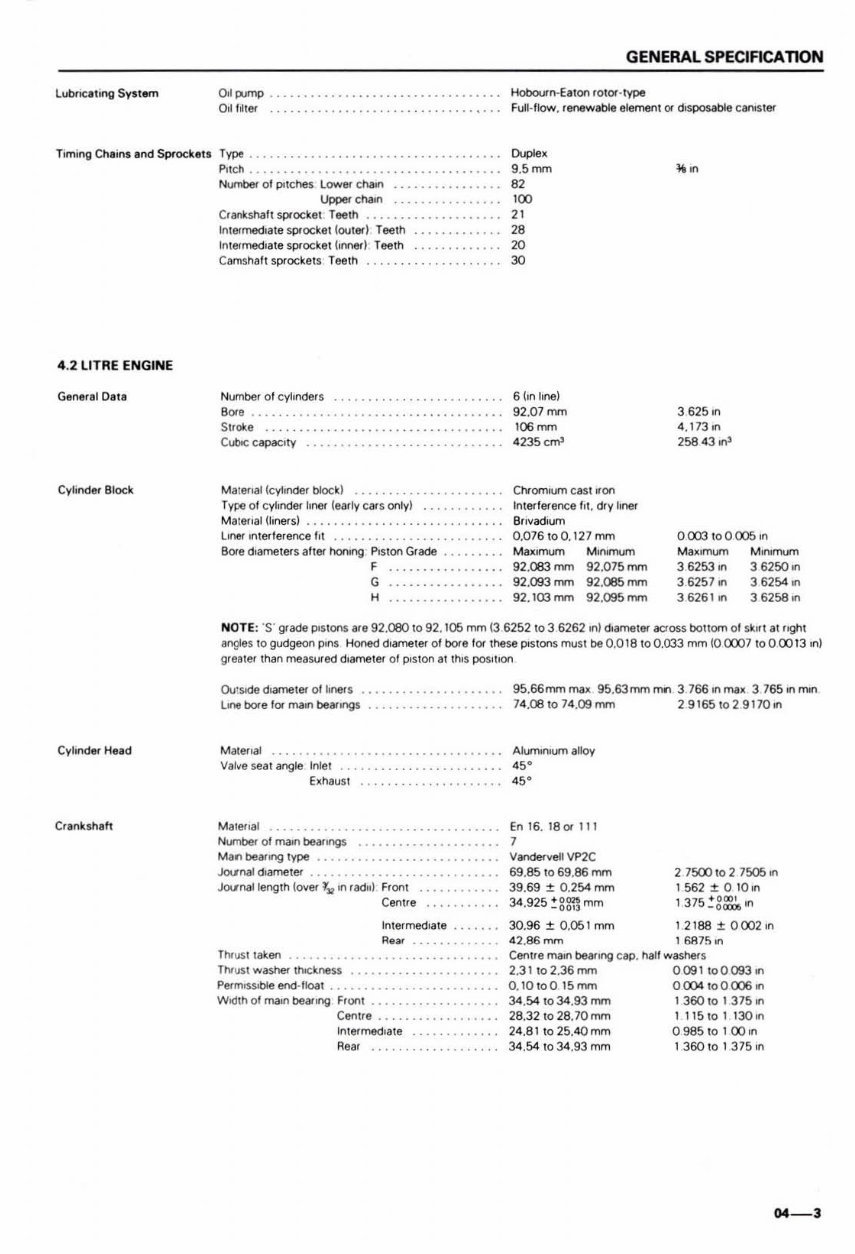
GENERAL SPECIFICATION lubncaling Syst em Hobourn-Eeton rOtOl - 1ype Full-'Iow. r~able element Of dIsposable C""'ster Timing Cha ins and Sprockell Type ........ .. ...... . .... ...... • ........ . """", 9.5mm 82 4.2 LITRE ENGINE Ganeral Data Cylinder Block Cylinder Head Cr.nksl"l.tt P,tch ..• •. Numbef 0 ' potches Loweo- chaIn ........ ..• . Upper Chain ..... ....... . .. . Crankshal tsprocket Teeth ..... . ...... ... . Inteo-medlate sprocket ~outer) Teeth Inteo-med,ate sprocket hnner) Teeth .... ...... . CamS halt sprockets Teeth Number 01 cylInder s . .. . ... ... ... .... ... .... . B Ofe • . . . .. .. . . . Stroke Cubo<: capaclly Malerlal ~cyltnder block) Type 01c yhnder I.ner ~eMl y c ar s only) MlIIllf lal ~hnefsJ lIner In terillfence ht ... .. ........... . . BOle d,ameters after honIng PIS tOn Grade ........ . F ... .. .. . G ... ... . . H .......... .• . '00 " 28 20 30 6 !In hne) 92.07 mm "J6~ 4235 c..-n3 ChramK.om cast "on Inlerlefence III. dry lIner Bflvadll)m 0.076 to O. 127 mm .... ,- 92.063mm 92. 093mm 92.103 rnm MInimum 92.075mm 92.085rnm 92.095mm ". 3 625 In 4 . 17310 258 43 '"' 0003 to 0 (X)5 In "",""""' 3 6253 on 3 6257 on 36261 on M ,n,mum 3 6250 on 3 6254 on 3 625810 NOTE : '5' Qfade POStons life 92.080 to 92. 1 05 mm ~3 6252 to 3 6262 In) dlClfTletef across bottom 0' skllt at r'9ht a ngles to gucJgeOr1 pons Honed d,ametef 01 bore 1 01 these POStons muSt be 0.018 to 0.033 mm (0 CXXl1 to 0 00 13 ,n) greatef than measUfed dlamatef or PIston at thIS POSlhOll Ov: SIde dlamatef of lIners . . Litle bore 101 n\3II"I beaflngs Mater Ial . .. .. Val.e seat angle Inlet .. Exhaus t NUf"I1bef oll1\3ln beMIf"I9$ ..... . Man bearong type ..•••... .... Jo.tnallength loYef f~ In radII ) Front Cent.e TI"II \I$t taken Inlefmed,ate , .. Thr\l$t ..... <tSher thockness ...... .. .... ...... •••. PermlSS.t:Jle end-'Ioat •.. Width 01 mall! bearIng Front Centre Intermed,ate Rear 95.66mm IT\iIIM 95.63mm fl1rI 3 166 In ffi8M 3 165 In mon 14.00 to 14.09 mm 29165 t02911011'"1 AluminIum alloy <S . .,. En 16. 1801111 7 Vandervell Vf>2C 69. 65 to 69.66 mm 39.69 :!: 0.254 mm 34. 925 ~ ggn mm 2 7500 to 2 7505 on 1562:!:0 1 0lfl 1375 ~ gg"n 30.96 :!: 0.051 rnm 4 2.66mm I 2168:t0002,n t SA75 ... Centr e rna ... beMtng cap. hall washer s 2.31102.36mm 009 1 to 0093 on 0.IOl o0 15 mrn 0 (X)4 100CX)6on 34.54 to 34.93 mrn I 360 10 1 315 ... 26.3210 28.70rnm 111 5101 130In 24.8 1 1025.40 mm 098510 1 00 In 34.S41034.93mm 1360101 3751n 04-3
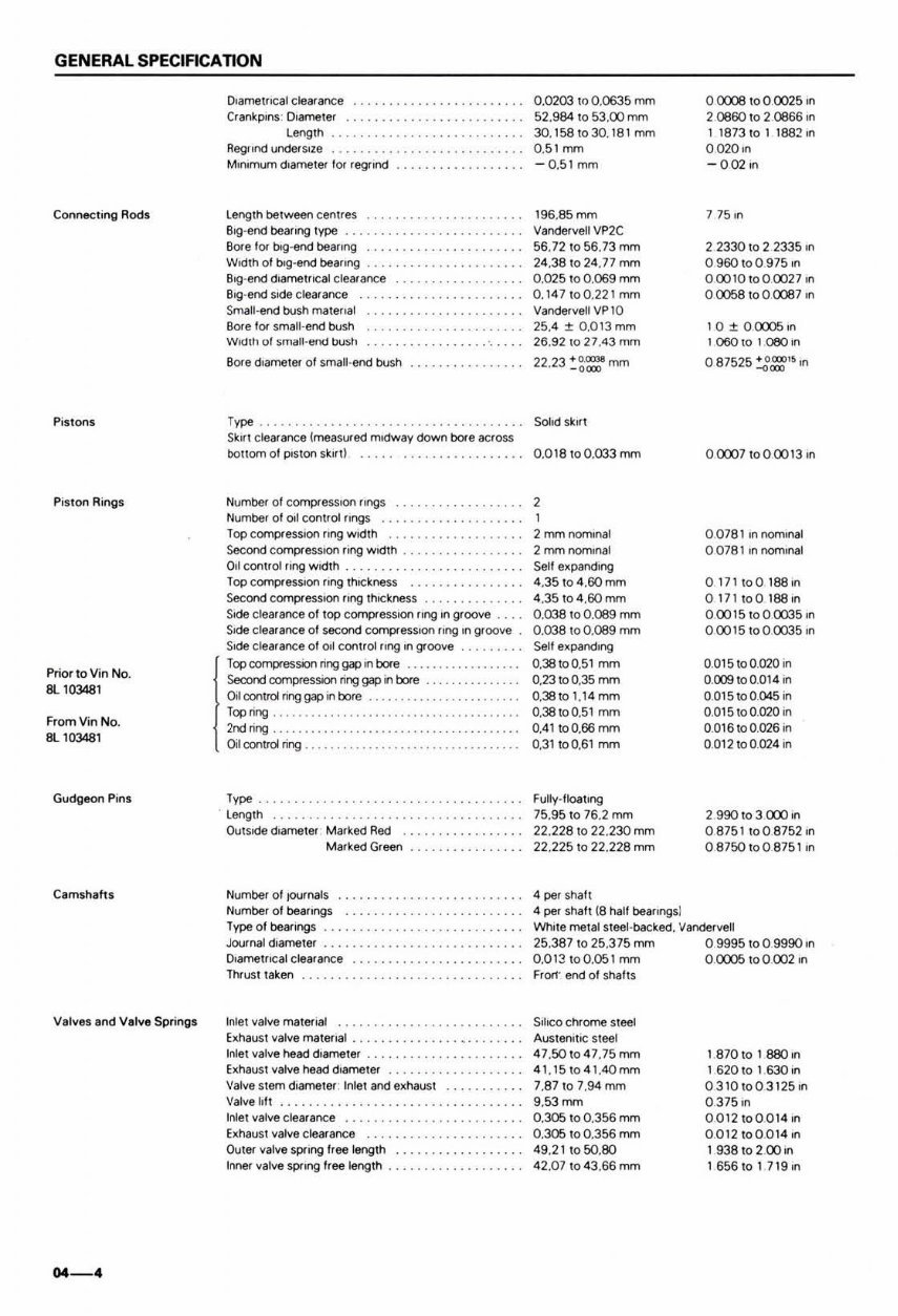
GENERAL SPECIFICATION Connecting Rods Pistons Pist on Ri ngs Prior to Vin No. 8L 103481 FromVin No. 81..103481 Gu dgeon Pins Camshaft s V.lvIIS and V.lve Spri ngs 04-4 D,ametrICal tlearance Cranl<.pms · D,ameter Length Regflnd UoIlde<sIza ................ • .•. ••• .•.• M,"'mum cloameter for regrind length between cenues Big -end bearing type . ............ •. Bore 1 01 !ltg-end beaflng .............. •. WH:!th 01 bog-end bearong .......... •. B,g-end dIametrICal clearance ...... •. BIg -end side clea< ance Small-end bush malenal BOfe fo< small· end bush Wod1l, 01 smal l-end bust' BOfe diameter of small·end bush Type . _ SkIn clearance (measured midway down bore &Cross bonom of p'ston skIn ! ........ . Number 01 compressIon rings .......... •. Number of 011 control flngS Topcompressl()Ilfingwidlh ... . ... . Second CQITIP(flSSIOfI ling width 0.1 control rIng width .. . ............ . Top CompresSIon flng thICkness Second comptession ftOg thICkness SIde clearance of top cornpresslOO ring In groove S,de clearance of second compr esslOO flng In groove Sode clearance of 011 Controlling In groove Topcompressionringgapinbore ................. . Second compression ring gap in bore ........... . 01 contra ring gap in bore ... . ......... . Top ring . 2nd ring . 01 contrd ring . Type . . length Ou tside diameter Marked Red Marked Green Number of tournals Number of beaflngs 1 ype of bearongs D,ametllcal clearance lhruSl taken Inlel valve material Exhausl valve malerlal . Inle1 valve head dlameler . Exhaust valve head <hameler Valve stem diameter' Inlet and exhaust Valve hft Inlet valve clearance ... ...... . .. . Exhaust valve clearance ... .. . ... . .... . ...... . Outer valve spflng free length Inner valve SPring free length ... . ....... . . 0.0203 to 0.0635 mm 52.984 10 53.00 mm 30.158 to 30. 181 mm 0.51 mm -0.51 mm 196.85 mm Vandervell VP2C 56.72 10 56.73 mm 24.38 to 24.77 mm 0.025100.069 mm 0.14 7100.221 mm VandervellVP10 25.4 ± 0.013 mm 26.921027 . 43mm 22.23 : ~~mm Solid skul 0.018 to 0.033 mm 2 2 mmnomlnal 2mmnomlnal Sel! expanding 4.35 10 4.60 mm 4.35104.60 mm 0, 038100. 089 mm 0.038 to 0 . 089 mm Sell e xpanding 0.38100.51 mm 0.23 to 0.35 mm 0.38 tOl.1 4mm 0.38100.51 mm 0.41100.66 mm 0.31100.61 mm Fully ·floatlng 75.95 1076.2 mm 22.2281022.230 mm 22.2251022.228 mm 4 per shafl 4 per shaft (8 half beallngsl 00.:0:1 1000025 ,n 20860 10 2 0866 In 1 1873 10 1 1882,n o 020,n -0021n 77510 22330 10 2 2335 10 0960 1 009 75 In 00010 1 000027 ,n o 0Cl58 10 0 00137 ,n 10±0(0J5,n 1060101 ceo 10 o 87525 ~::'~ In 0<XX>71000013on 00781 In nominal 00781 In nom,nal 0171 1 00 188 In 017 1\ 00 188 In 0. 0015 1 000035 ,n 00015 1000035 In O.ot5 10 0.020 in 0.009 toO.014 in 0. 015toOJ)45in O.ot5 10 0.020 in 0. 016toO. 026in 0.012 to 0.024 111 2. 9901030::010 08751 '0 08752 In 08750 ' 00875110 White melal sleel·backed. Vandefvell 25.3871025.375 mm 09995 100.9990 10 0.013100.051 mm Frorl ' end 01 shafts SIlICO chrome s teel AuslenltlC s teel 47 .5010 47 .75mm 4 1.1510 4 1.40mm 7.87107.94 mm 9.53mm 0.305 10 0.356 mm 0.305 10 0.356 mm 4 9.211050.80 42.07 10 43 .66 mm OOCOS.o0002,n 18 70 10 \ BBO,n 1 620 \01 .630 In 0310 toO.3125,n 0.37510 0012 toOOl 4 ,n 0. 012 100.014 ,n 1938 1 0200,n 1656 .0 1 719,n
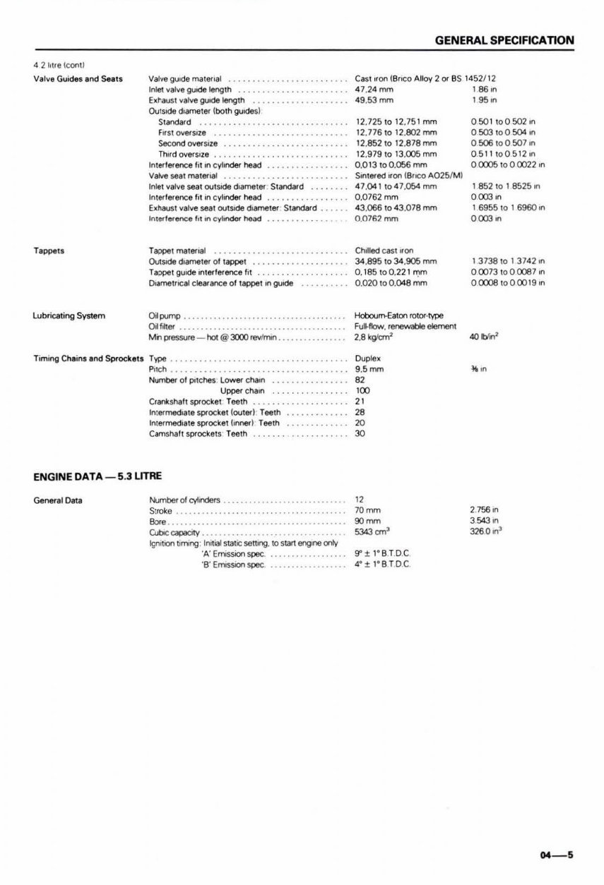
42 Mr. tconU Valve Guides and SealS Tappen Lubricatjng System Valve gwde male",,1 Inlet valve goode length btausl valve goode length ................... . Outsode d'3ffleW lboth guodM) Standard ...... .. ....... . fil s! OIIerSl18 . Second oYefSiZI ThIrd overSi ze ... .......... . If\lerferenc:e ,, 111"1 cylinder head ........ . Vahle seal materllIl Inlet valve seal outSIde d, ameter Standafd Interference fil,n cylinder head EJthausI valve seat outSide doameter Standard Int erference "I ... cyloodct head ... h ope'malenal .... . ................ _. , .. Outsode diameter 01 tappet ... . .. . hopei guIde Interference lit Dlamet"c al clearat'lCe of tappet In guide OiIporfl) ............. . ........... . Oilfllter ..... . ....... . Mh pressure - hoi @ 3000 ~ ... , T~ .... ... ............... . ,., Numbef 01 potches Lower chaon Uppet cha,n Crankshaf t spocke! Teeth ..... . ..... •. . ...... Intermediate sprocket louted Teeth InlaflTled"le sprocket hnned Teeth ...... •. Camshat\ sprockets Tefllh ... . ENGINE DATA - 5.3 LITRE General Data t-i.Jmbef of cyIindefs . . . . . . . . . . . . .. . . ....... . S:roke . Bore .... Q.bc~ . Igl'lll oon I tITlIng : 11111 1(11 SialiCS6tllng. 10 start engone crlv 'A' Emission spec. 'B' EmISSion spec ..... .... ...... . GENERAL SPECIFICA nON Casl ,ron IBrlCO Alloy 2 or as 1 452/12 4 7.24mm 1860n 49.53 mm I 95 on 12.725 1 012.751 mm 12.776 1 01 2.802 mm 12.852 1 012.878 rTVT1 12 . 97910 13.CXl5 mm 0 .0 13100.056 mm Sonleo-ed.ron (BrICO A025/M) 4 7.04110 47 .054 mm 0.0762mm 43.066 10 4 3.078 mm 0. 0762mm Choll ed casllf on 34 .895 1034 .906 mm 0.185 1 00. 221 n:wn 0. 020 10 0. 048 mm Hoboum-Eaton rolor·type F\ll-fIow. renewable element 2.8 kg c:rn2 Duplex 9. 5mm 82 100 21 28 20 30 9" ± I· B.T.O.C 4" ± I· B.T.OC. 050110050211'1 0503 1 00 504 on 0506 1 00507,., 05 111005 12 11'1 o IX05 10 0 0022 In 1 852 10 1 8525,., 000311'1 1 6955 10 1 6960 In 0003_ 13738 10 1 3742 ,n 00073 10 0 0Cl67 In 0CXX)8 1 0000 19 ,n 2.75611'1 3. 54311'1 326 0 on 3 04_5
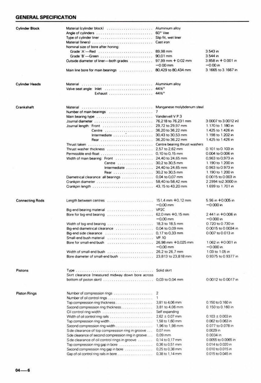
GENERAL SPECIACA nON Connecting Rods Pi stons Pis10n Ri ngs 04-6 Malenal!cyIinder block) ........ • ...• ......... AIunwloum alloy Angle 01 cylinders ........................... 60- Vee T't'Pe 01 cylinder line\' . . . . . . . . . . . . . . . . . . . . . . • •• Slop "I. _ tlinel" t.ia1e.- 18i U,,*sl . . • • . . . . . . . . . . . • • . . . . . . . .. CII$1 won NorrHnaI5Ize of bore alIef honing. Gr!lde 'A'-RecI ......... . Gr8de 'B '-Green ................ . Outside (jiamelef 01 loner - both grades ....... •.. Malena! ..... . B9.98mm 90.0 1 mm 97 .99 mm + 0, 02 mm -O, oomm 80.429 to 80.434 mm Valve seal angle" Inlet ......... •...•.. 44'h · bhausl ....... • ... • . . 44 1h · Materoal Number 01 ntalO beaongs ........... . . Main bear.ng type .. .......... . . Journal diameter .. ............... •. .. Joornallength" "Front ........... •. een ue .......... . InIMmedla te .. R.~ Thrust laken ........... . Thrust washef thockne~ .. Pem'llSSobie enct-lioat .. Width ollT\&ll'l bear.ng Front Cen1Je Int8fmedl81e ....... •. Rear Dlemel"cal clearance all be8f1r19S Oan~pm dIameter ..••• . ••. Oankpon length ••. LengTh between cenlles BIg·end bearll'lg matenal &we l or bIg·end bearll'lg Wldlh of bIg·end bearll'lg .................. . . . . BIg ·end diametrical clearance BIg·end side clear a nee ........... • ... • ....... Small·end bush mal Ofl81 Bore tor small·end bush &we diamete< 01 small· end bush Ttpe • .... ....... . Sort clearance ( measured modway down bore across Manganese molybdenum s~ 7 Vandefvell v P.3 76.2181076.231 mm 29.72 10 29.97 mm 36.20 10 36.22 mm 30.43 10 3O.f>3 mm 36.20 10 36.22 mm Cenlle bearrng I!YOSI washef$ 2.57 1 02.62 mm 0.10 1 00. 15mm 24.40 10 24.65 mm 30.2 10.30.5 mm 24 .40 10 24 .65 mm 30.2 10.30.5 mm 0. 04 100.07 mm 58.40 10 58.42 mm 43.15 , 043.20mm 15 1.4 rrrrn + 0. 12 mm -D. oorrrn VP2C 62. 0mm +0. 15 mm -o.oomm '8.3 10 18.5 mm 0.04 to 0.09 mm 0.17 1 00.33mm VP 10 26.98 mm + 0.025 mm - O.oomm 26.21026 .7 mm 23 . 8'31023.818mm SoM sklr l bollom of POSlon sk,n) . . . . . . . . . . . . . . . . . . 0.03 10 0. 04 mm J-«Jrnbef 01 corrrpr-essron nngs ................. .... 2 ~r1lbef 01 oil conlro1 nngs ................ . Topcompressroo nng thrdo:: ness . Second cornpressron nng thrckness . 0,1 control ring width . . Width of oil conlro1 nng ""Is .... . . Top CCII'T'pe5SIOI\ nng WIdth .......... .. . Second cornpteSSIIOIl nng IMdth .......... •.•.•...•. 5 de clearance O /lop compressron ling In groove .. . Sde doorooce of sean:! cornpressron rng ., grocwe .. . Sde clearance of 011 oon trol lingS ,n groove .. Top compresson rng gap on bore ...... .. ......... . Second cornpressron nng gap ,n bore . . ............ . Gap 01 011 conlro1 rrng ra"s 11 bore ....... ........... . 3. 81104.06mm 3.81 10 4.06 mm Self expan:j ng 2.62:t 0.07 mm 1.58101. 60mm 1.96IOI .98mm 0.07mm O.09mm 0.1 410 0.17 mm 0.36100.51 mm 0.25 100.38 mm 0.38 10 1.14mm 3 543 on 3 544 ,n 3. 858,n + 000lm - Ooo, n 316651031667,n 3 CXlO7 10 3 0012 on) 1 170 1 01 180,,, 14 25101 4 2611'1 119810 1. 20211'1 1 4 25 to 1 4 26 on o 1 01 toO 103 11'1 o CX>4 1 00 (X)6 11 0. 963 1 00.973 on 1190 1 012000n 0963 ,00973on I 190 1 012000n 000 15100 003,1'1 2 2994 102 3000 , 1'1 1699101701,1'1 2 44 111'1 + 0(X)6 11'1 - OCXlO on o 720 10 0 730 11'1 0 0015 1000034 on 0007 10 0013 0n 1062,1'1 + Oool,n -0 CXlO ,1'1 '031010511'1 0 93 75 1 00 937711'1 0 00121000017., 0.150 to 0.160 ,n 0 150 ' 00 160 ,1'1 0 103 :t0003on 0062 toO 063 on 0077 100078,1'1 o(l029. 0 0004 ,n o 0055 1 000065 on 0 014100 020 ... 0010100015 ... 0015 1 00 04511
The 1979-1990 Jaguar XJ Series 3 OEM (XJ6/XJ12) Service & Repair Manual is a comprehensive resource for Jaguar owners and professional mechanics. This manual covers all aspects of servicing and repairing the Jaguar XJ6 and XJ12 models from 1979 to 1990, delivering expert guidance on both routine maintenance and complex repairs.
Featuring clear, detailed instructions, the manual provides step-by-step procedures for a wide range of repair tasks—from engine overhauls to electrical system troubleshooting—ensuring you have the precise information you need at your fingertips.
Key features of the 1979-1990 Jaguar XJ Series 3 OEM (XJ6/XJ12) Service & Repair Manual include:
Extensive coverage of both the XJ6 and XJ12 models
Detailed diagrams and illustrations to clarify repair processes
Comprehensive troubleshooting guides for effective problem resolution
Step-by-step instructions for all service procedures
Expertly researched and compiled by experienced Jaguar technicians
Compatible with models from 1979 to 1990
Whether you are a seasoned professional or a dedicated Jaguar owner, this service and repair manual is an essential resource to ensure your vehicle remains in peak condition.
Recently Viewed
5,521,897Happy Clients
2,594,462eManuals
1,120,453Trusted Sellers
15Years in Business
Price:
Actual Price:
1979-1990 Jaguar XJ V6 V12 Series 3 Service & Repair Manual