1994-1997 Jaguar XJ Series X300 X305 X306 Service & Repair Manual
What's Included?
Lifetime Access
Fast Download Speeds
Offline Viewing
Access Contents & Bookmarks
Full Search Facility
Print one or all pages of your manual
\
Powertrain Automatic Transmissions Service Manual CON TENTS Section Title SRO Page Foreword ........................................................................... ii I ................ Service Tools & Equipment ........................................................... iii I1 ................ Torque Tightening Specifications ....................................................... iii 111 ............... Service Materials .................................................................... iii IV ............... Service Data ....................................................................... iii 1.1 .............. General Description .................................................................. 1 7.1.1 ............. Gear Range ......................................................................... 1 1.1.2 ............. lubrication Circuits .................................................................. 3 1.1.3 ............. CoolerCircuit ....................................................................... 3 1.2 .............. Transmission Components ............................................................. 5 1.2.1 ............. Torqueconverter .................................................................... 5 1.2.2. ............ Planetarv Gear Sets ................................................................... 5 1.2.3 ............. Torque Converter Clutch .............................................................. 5 1.2.4 ............. Pulse Width Modulated (PWM) Solenoid ................................................. 6 1.2.5 ............. Input And Output Speed Sensors (TISS)And (TOSS) ........................................ 6 1.2.6 ............. Shift Solenoids ‘A’ And ‘6’ ............................................................. 6 1.2.7 ............. Variable Force Solenoid/Motor (VFS) ................................................... 6 1.2.8 ............. Transmission Control Module (TCM) .................................................... 6 1.2.9 ............. Pressure Switch Manifold (PSM) ........................................................ 6 1.2.10. ........... Transmission Temperature Sensor ....................................................... 6 1.2.11 ............ Accumulators ....................................................................... 6 1.3 .............. Oil Pump And Internal Valves .......................................................... 7 1.3.1 ............. Pressure Regulator Valve Train ......................................................... 7 1.3.2 ............. Reverse Boost Valve .................................................................. 7 1.3.3 ............. Torque Converter Clutch Enable Valve ................................................... 7 1.3.4 ............. Torque Converter Clutch Shift Valve ..................................................... 7 1.3.5 ............. Converter Limiting Valve .............................................................. 7 1.4 .............. Valves In Valve Body ................................................................. 8 1.4.1 ............. Torque Signal Compensatory Valve ..................................................... 8 1.4.2 ............. Checkball Valves ..................................................................... 8 1.4.3 ............. Active Components For Each Gear Ratio ................................................ 10 1.5 .............. Hydraulic Circuit Diagrams ........................................................... 11 1.6 .............. Fault Diagnosis ..................................................................... 24 1.6.1 ............. Initialchecks ....................................................................... 24 1.6.2 ............. Engine Tune ........................................................................ 24 1.6.3 ............. Stall Test ........................................................................... 24 1.6.4 ............. Road Test .......................................................................... 24 1.6.5 ............. Electrical Checks .................................................................... 24 1.6.6 ............. Transmission Fault Codes ............................................................. 25 1.7 .............. Service Operations .................................................................. 26 1.7.1 ............ Rear Servo Assembly - Renew (6.OL) .............................. 44.34.13 ............ 26 1.7.2 ............. Front Servo Assembly - Renew (4.0 liter SC and V12) ............... 44.34.17 ............ 27 Remove For Access and Refit (4.0 liter SC and V12) ................. 44.40.05/90 ........ 28 . 7.3 ............ Valve Body And Accumulator - . 7.4 ............ Valve Body Assembly- Renew (4.0 liter SCand V12) ................ 44.40.06 ............ 29 Issue 1 August 1994 i
Powertrain Automatic Transmissions Service Manual 0 FORE WORD This manual provides information relevant to the servicing of Automatic Transmission Units 4L8Ck-E (irrespective of the vehicle range to which the unit isfitted). The manual should be used in conjunction with the relevant Vehicle Service Manual (VSM) and Electrical Diagnostic Manual (EDM). It assumes that the transmission has been removed from the vehicle, in accordance with the Vehicle Service Manual, and is in a clean condition and all service tools and materials are available. The manual is divided into sections covering: 0 Sub-section 0 - service information 0 Sub-section 1 - detailed mechanical description 0 Sub-section 2 - general data (service-relevant) 0 Sub-section 3 - hydraulic circuit diagrams 0 Sub-section 4 - troubleshooting 0 Sub-section 5 - service repair operations. An index can be found at the rear of the manual. Note: For information relating to in-vehicle operations, refer to the Vehicle Service Manual. issue 1 August 1994 ii
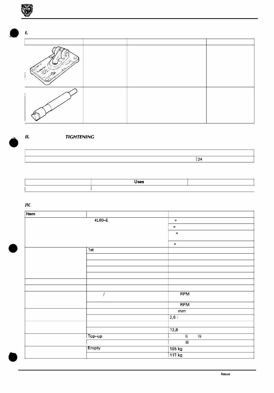
Powertrain Automatic Transmissions Service Manual Illustration Jaguar Number JD 192 JD 193 Description Notes Pin checking tool Stepped gauge pin 11. TORQUE TlGH TENING SPECIFICATIONS Nut on checking tool JD 192 I34 Description UseS Notes I To be issued I I I Item I Description Explanation of model designation 4L80-E Gear ratios 1st 2nd 3rd 4th Reverse Maximum torque (into the converter) Maximum torque (at the turbine shaft) 4 liter s / c 6.0 liter Stall torque ratio Drain and refill only Complete fill Engine torque Gearbox torque Maximum shift speed (all upshifts) Torque converter Diameter Transmission fluid capacity IU SERVICE DATA Data 4 = 4 Speed L = Longitudinal mounting 80 = Series (based on relative torque capacity) E = Electronic control 2,482 : 1 1,482 : 1 1,000: 1 0,750: 1 2,077 : 1 597 N m 1200 N m 5500 RPM 6000 RPM 310 mm 2,6: 1 7.3 liter 12,8 liter Transmission weight 1 Dexron II E or 111 Transmission fluid I TOP-UP Empty I105 kg Complete with fluid I117 kg I Fill I Dexron 111 Issue 1 August 1994 iii
iv
Powertrain Automatic Transmissions Service Manual GENERAL DESCRIPTION This manual provides information relating to the 'Powertrain' (formerly Hydra-Matic) 4L80-E automatic transmissions fitted to the X- 300 vehicle range. The Powertrain 4L80-E is a four-speed, high torque capacity, electronically controlled automatic transmission, which comprises a torque converter with lock-up direct drive clutch and three planetary gear sets. Five multiple disc clutches, one intermediate sprag clutch assembly, two roller clutch assemblies and two band assemblies provide the drive el- ements necessary for correct sequential gear engagement and operation. The torque converter containing a pump, turbine (rotor), a stator assembly, and a clutch pressure plate splined to the turbine, acts as a fluid coupling for smooth torque transmission from the engine. The converter also supplies addi- tional torque multiplication when necessary, and the torque converter clutch (TCC) pressure plate provides a mechan- ical direct drive or 'lock-up' above a certain speed in top gear for greater fuel economy. Gear shift operations are controlled from the Transmission Control Module (TCM), which governs the electronically controlled valve body situated within the transmission. Three planetary gear sets provide reverse and the four forward ratios, the changing of which is fully automatic in rela- tion to load, vehicle speed and throttle opening. The transmission control module (TCM) receives and integrates vari- ous vehicle sensor input signals, and transmits operating signals to the solenoids located in the control valve assembly. These solenoids govern the transmission operating pressures, upshift and down-shift gear selection patterns, and also the torque converter clutch operation from a pulse width modulated solenoid control. The performance mode switch provides for selection of 'sport' or 'normal' mode as required by the driver. The switch input to TCM changes the gear shift pattern such that in 'sport' mode, shifts take place at higher engine speeds. The 'kickdown' facility is activated by full downward travel of the accelerator pedal, providing a signal to TCM request- e ing greater acceleration hence downward gear shifts. 1.1.1 Gear Ranges Selectable gear positions are: P- Park, R -Reverse, N - Neutral, D - Drive, 3,2. The selected gear is displayed on a gear selection illumination module located above the selector mechanism. P- Park position of the selector lever provides a mechanical locking of the output shaft of the transmission, and as such, must only be engaged when the vehicle is stationary. In addition, and for extra safety, the handbrake should also be applied. It is necessaryto have the ignition on and the footbrake applied to move the selector lever from the Park posi- tion. For ignition key removal the selector lever must be in the Park position. The engine can be started in the Park position. R - Reverse enables the vehicle to be operated in a rearwards direction. The engine cannot be started in the Reverse position. N - Neutral position enables the engine to be started and operated without driving the vehicle. It also allows the vehicle to be moved manually for access, ie. for removal of the propeller shaft. D - Drive position allows the automatic selection of all four forward gear ratios during normal driving conditions for maximum efficiency and fuel economy. On acceleration, down-shifts are obtained by depressing the accelerator pedal or by manual selection. The engine cannot be started in this position. 3 - Manual third position allows automatic operation of the three lower gear ratios but inhibits selection of the fourth ratio. This position is used for towing a trailer or negotiating hilly terrain when greater engine braking control is re- quired. The engine cannot be started in this position. 2 - Manual second position allows automatic operation of the two lower gear ratios but inhibits selection of the third and fourth ratios. This position is used for heavy traffic congestion or negotiating hilly terrain when even greater en- gine braking control is required than is provided by manual third. This ratio may be selected at any vehicle speed - even if the transmission is in third or fourth ratio, the transmission will immediately down-shift to second gear pro- vided the vehicle speed is below 137 km / h (85 mile / h). The engine cannot be started in this position. &@: With the performance mode switch in the 'normal' position, the vehicle will pull away in second gear. However, if more than 75 per cent of throttle is applied when the vehicle speed is between zero and 13 km / h (8 mile / h), then first gear will be selected. From 13 to 61 km / h (8 to 38 mile / h) first gear is obtainable by 'kickdown'. In 'sport' mode the vehicle pulls away in first gear and the transmission operates fully in all four forward gears. 1 Issue 1 August 1994
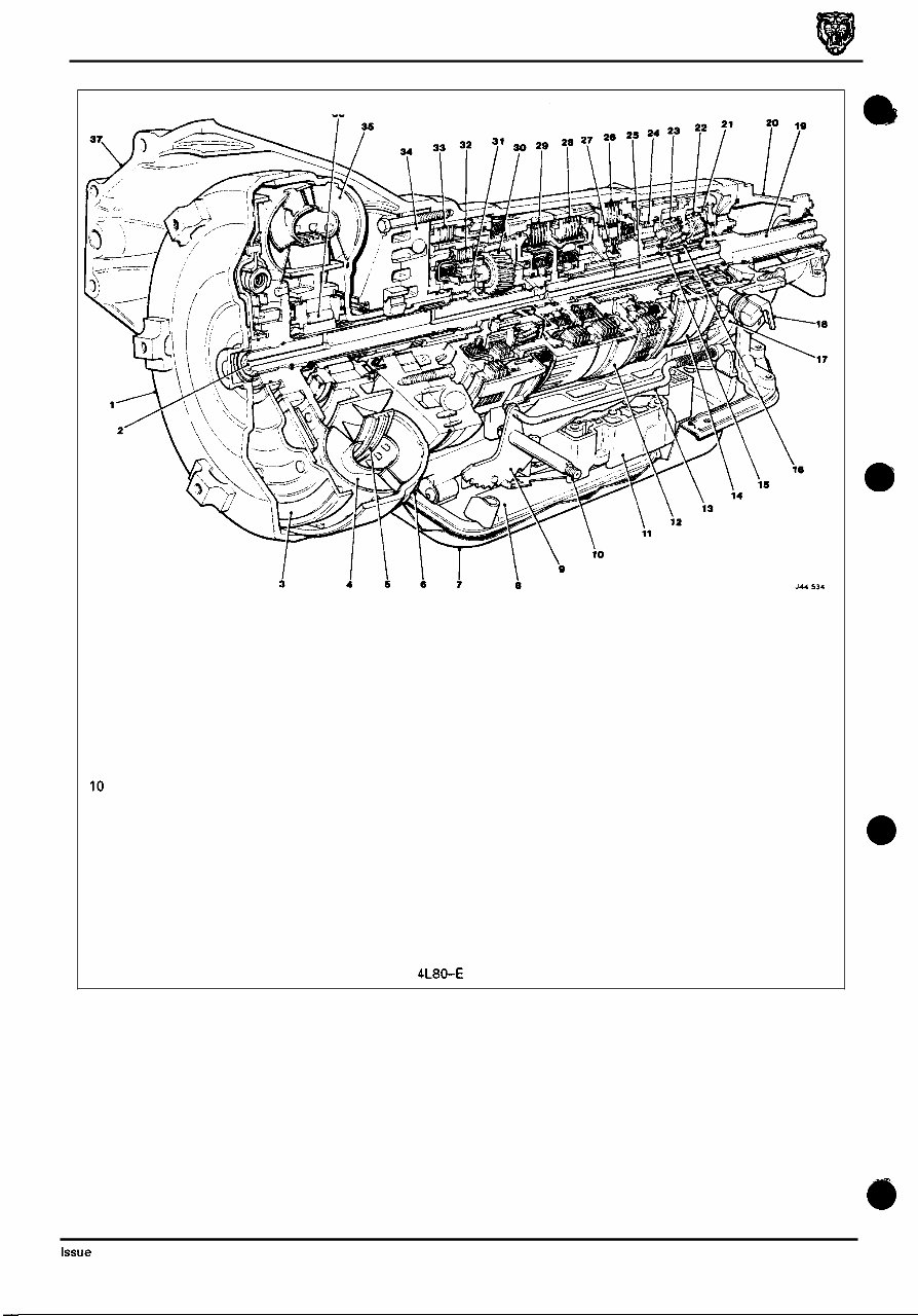
Powertrain Automatic Transmissions Service Manual 1. 2. 3. 4. 5. 6. 7. 8. 9. 10 11. 12. 13. Torque converter 14. Turbine shaft 15. Pressure plate 16. Converter turbine 17. Converter stator 18. Variable force motor solenoid 19. Sump pan 20. Filter 21. Interior detent lever 22. Manual shaft 23. Control valve 24. Front band 25. Parking lock actuator 26. Rear band 27. Sun gear shall 28. Sun gear 29. Parking lock pawl 30. Transmission case 31. Output shall 32. Rear extension housing 33. Rear internal gear 34. Output planetary carrier assy 35. Reaction planetary carrier assy 36. 'LO' roller clutch 37. Main shaft Intermediate clutch Intermediate sprag clutch Direct clutch Forward clutch Overdrive planetary carrier assy Overdrive roller clutch Overrun clutch Fourth clutch Pump assy Converter pump Stator roller clutch Output speed sensor Fig. 1 Powertrain 4L80-E Transmission assembly Issue 1 August 1994 2
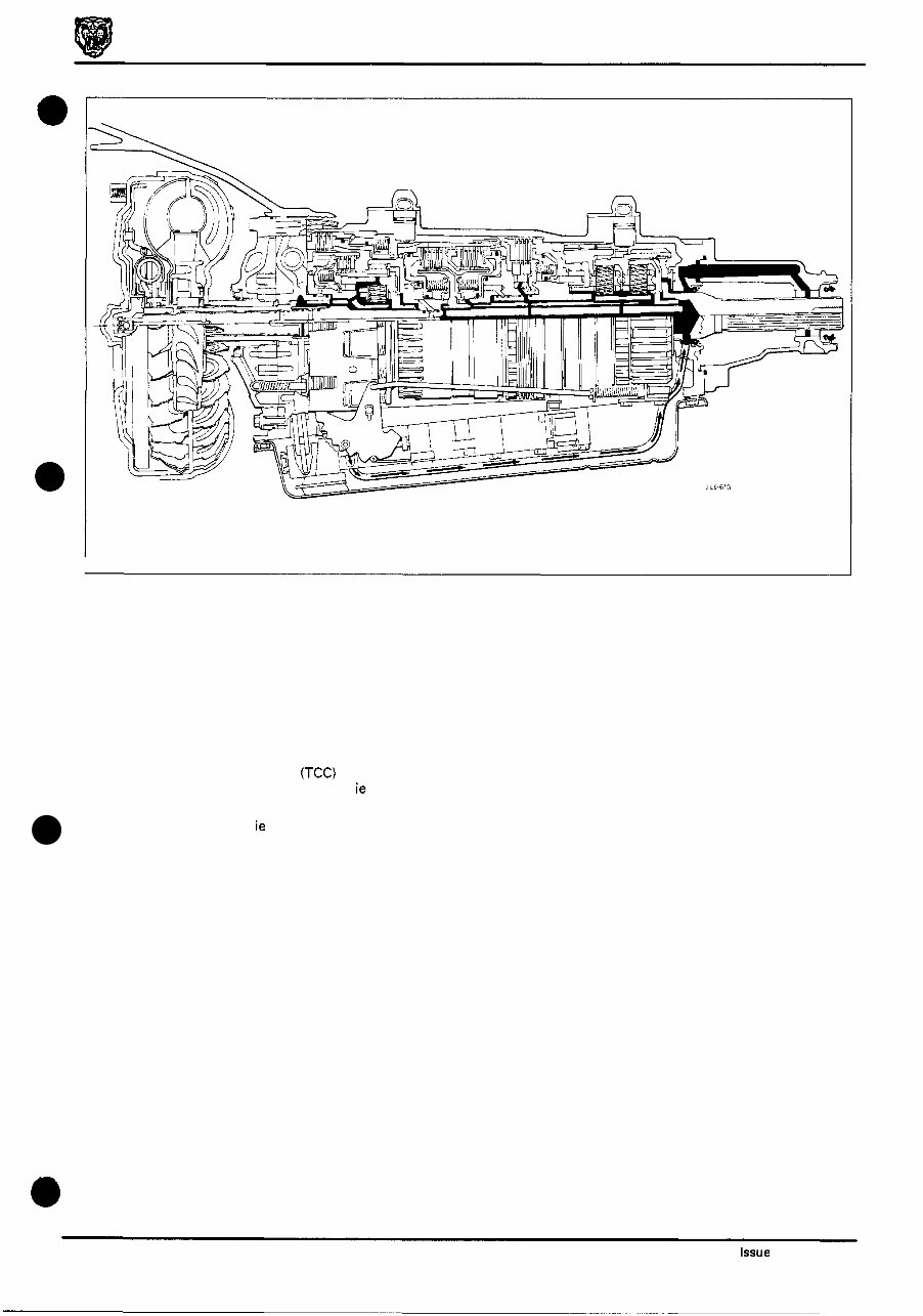
Powertrain Automatic Transmissions Service Manual JrL-615 Fig. 1 Transmission lubrication flow 1.1.2 Lubrication Circuits Transmission oil passes from the transmission unit, through the oil cooler and returns to the transmission unit via a connector in the case, into the valve body and into the lubrication pipe. The fluid is then routed to the rear of the trans- mission to lubricate the rear case, the rear extension housing bearing and the rear gearsets. Lubricationfluid is also routed through the pump assembly and into the overrun clutch housing where it passes to the various apply components to cool and lubricate the transmission clutches and gear sets. 1.1.3 Cooler Circuit With the torque converter clutch (TCC)released, transmission fluid returning from the torque converter is fed through the TCC shift valve into the cooler circuit, ie through the cooler feed pipe to the transmission cooler in the radiator and then back to the transmission unit lubrication circuits. When the TCC is applied, ie the shift valve in the apply position, regulator converter fluid is passed through the valve and into the cooler circuit as described above. 3 Issue 1 August 1994
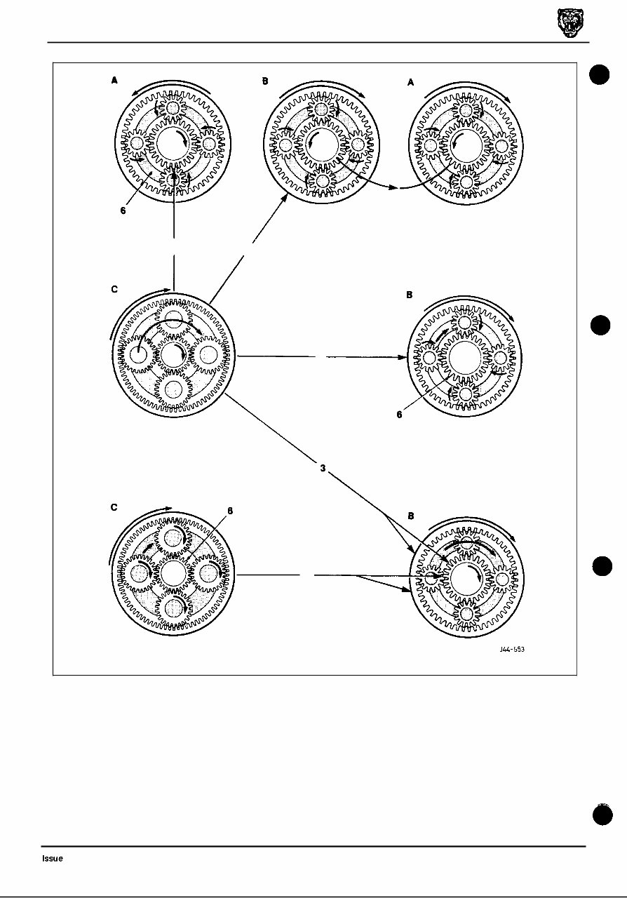
Powertrain Automatic Transmissions Service Manual 1.2 TRA NSMlSSlON COMPONENTS 1.2.1 Torque Converter The torque converter is a three element (single stator) unit which acts as a fluid coupling to connect the engine power smoothly to the transmission gear train, and as a torque multiplier to provide extra power when pulling away from rest. The three elements of the converter are the pump (impeller), the turbine and the stator. 1.2.2 Planetary Gear Sets Three planetary gear sets are used in this transmission: 'overdrive', 'reaction' and 'output'. Each gear set comprises a center or sun gear, an annulus or internal gear, and a planetary carrier assembly which con- tains the smaller planet gears. Direct drive in a planetary gear set is obtained when any two parts of a gear set rotate in the same direction at the same speed, thus driving the third component at the same speed. The planetary gears in this case act as wedges to drive the entire gear set as one unit and therefore the output speed of the transmission is the same as the input speed from the torque converter. Conversely, a planetary gear set reverses the direction of power flow when a carrier assembly is held stationary and power is applied to the sun gear thus causing the planetary gears to act as idler gears to drive the internal gear in the opposite direction. In first, second and third gears, the 'overdrive' roller clutch retains the 'overdrive' sun gear and carrier assembly to - gether, thereby driving the internal gear at the same speed. 0 In first gear, the 'output' internal gear drives the 'output' carrier planet gears clockwise, which causes the sun gear to rotate anti - clockwise. As the 'output' sun gear and the 'reaction' sun gear are common, the 'reaction' carrier planet gears rotate clockwise. The 'reaction' carrier, being held stationary by the 'LO' roller clutch, then causes the 'reaction' carrier planet gears to drive the 'reaction' internal gear and the output shaft, ie first gear. Second gear is obtained when the 'output'/'reaction'sun gear is held stationary by the intermediate clutch and there- fore when the 'output' carrier planet gears are driven clockwise by the rear internal gear, the planet gears rotate clock- wise round the stationary sun gear. The 'output' carrier planet gears drive the 'output' carrier assembly and 'output' shaft clockwise, ie second gear. Third gear is obtained when the direct clutch is applied; the power flow from the 'overdrive' planet gears and the for - ward clutch housing is then transferred to both the 'sun' gear and the 'output' internal gear. With the power flow through the 'overdrive' planetary gear set being a direct drive, and with both the sun gear and the internal gears of the 'output' planet gear set driving at converter turbine speed, the 'output' planetary gears act as wedges and drive the 'output' carrier assembly and output shaft together, ie direct drive, third gear. In fourth gear, the 'overdrive' sun gear is held stationary by the fourth clutch being applied, then the 'overdrive' carrier being driven clockwise, the 'overdrive' planetary gears rotate clockwise also on their axes around the stationary sun gear. This causes the planetary gears to drive the 'overdrive' internal gear clockwise and so an 'overdrive' ratio is ob- tained through the 'overdrive' planetary gear set. In reverse gear, the rear brake band is applied to hold the 'reaction' carrier stationary while the direct clutch is applied to supply clockwise power flow to the sun gear. Power flow from the 'overdrive' planetary gear set being a direct drive, the sun gear drives the 'reaction' planetary gears anti - clockwise which drives the 'reaction' internal gear ('output' carrier assembly) anti - clockwise ,ie reverse gear. 1.2.3 Torque Converter Clutch When a predetermined speed is achieved in fourth gear, the torque converter clutch is enabled by the transmission control module through the pulse width modulated solenoid and a clutch plate provides a direct drive so reducing fuel consumption. Pulsing the solenoid causes the TCCvalve to modulate pressure against the TCC. This pulsing or modu - lated pressure allows the TCC to slip slightly so providing a smooth apply and release of the TCC. If the transmission fluid exceeds a temperature of 125OC the TCC will also apply in second and third gears to reduce friction generated in the torque converter. 0 Issue 1 August 1994 5
The Jaguar XJ Series X300 X305 X306 1994-1997 Service Manual is a comprehensive guide that provides detailed information and instructions on the servicing and maintenance of Jaguar XJ models from the X300, X305, and X306 series.
Designed for both professional technicians and DIY enthusiasts, this service manual is an essential resource for anyone who owns or works on these Jaguar models. It covers a wide range of topics, including engine, transmission, suspension, brakes, electrical systems, and more.
With this service manual, you'll have access to step-by-step procedures, diagrams, and illustrations that will help you accurately diagnose and repair any issues with your Jaguar XJ. Whether you need to perform routine maintenance tasks or tackle more complex repairs, this manual will be your go-to guide.
The Jaguar XJ Series X300 X305 X306 1994-1997 Service Manual is organized in a user-friendly manner, allowing you to easily navigate through different sections and find the information you need. It also includes helpful tips and troubleshooting advice to assist you in solving common problems.
Models covered in this manual:
Jaguar XJ6 X300 1994-1997
Jaguar XJ12 X305 1994-1997
Jaguar XJR X306 1994-1997
Whether you're a Jaguar owner, a repair shop, or a Jaguar enthusiast, the Jaguar XJ Series X300 X305 X306 1994-1997 Service Manual will prove to be an invaluable resource for maintaining and repairing these elegant and powerful vehicles.
Recently Viewed
5,521,897Happy Clients
2,594,462eManuals
1,120,453Trusted Sellers
15Years in Business
Price:
Actual Price:
1994-1997 Jaguar XJ Series X300 X305 X306 Service & Repair Manual