

Jaguar XJ 2003 2004 2005 2006 2007 2008 2009 Service Manual
What's Included?
Fast Download Speeds
Offline Viewing
Access Contents & Bookmarks
Full Search Facility
Print one or all pages of your manual

Electrical Guide
XJ
Sedan
including LWB
2005 Model Year, VIN: G34528 onwards
Published by Technical Communications, Jaguar Cars Limited
Publication Part Number JJM 10 38 21 501, September 2004
www.JagDocs.com

DATE OF ISSUE: September 2004
Preface Jaguar XJ 2005
Preface
While every effort is made to ensure accuracy, design changes to the vehicle may be made in the period between the completion of
this publication and the introduction of vehicles.
All rights reserved. No part of this publication may be reproduced, stored in a retrieval system or transmitted, in any form: electronic,
mechanical, including photocopying, recording or other means without prior written permission from the Service Division of
Jaguar Cars Limited.

2 DATE OF ISSUE: September 2004
Table of Contents: Figures Jaguar XJ 2005
FIGURES
Fig. Description Variant
Table of Contents: Figures
01 Power Distribution
Fig. 01.1 . . . . Main Power Distribution . . . . . . . . . . . . . . . . . . . . . . . . . . . . . . . . . . . . . . . . . . . All Vehicles
Fig. 01.2 . . . . Battery Power Distribution: Part 1 . . . . . . . . . . . . . . . . . . . . . . . . . . . . . . . . . . . All Vehicles
Fig. 01.3 . . . . Battery Power Distribution: Part 2 . . . . . . . . . . . . . . . . . . . . . . . . . . . . . . . . . . . All Vehicles
Fig. 01.4 . . . . Ignition Switched Power Distribution: I (Accessory) . . . . . . . . . . . . . . . . . . . . . All Vehicles
Fig. 01.5 . . . . Ignition Switched Power Distribution: II (Run) . . . . . . . . . . . . . . . . . . . . . . . . . . All Vehicles
Fig. 01.6 . . . . Switched System Power Distribution: Part 1 . . . . . . . . . . . . . . . . . . . . . . . . . . . All Vehicles
Fig. 01.7 . . . . Switched System Power Distribution: Part 2 . . . . . . . . . . . . . . . . . . . . . . . . . . . All Vehicles
Fig. 01.8 . . . . Engine Management Switched Power Distribution . . . . . . . . . . . . . . . . . . . . . . All Vehicles
02 Battery; Starter; Generator
Fig. 02.1 . . . . Battery; Starter; Generator: V6 . . . . . . . . . . . . . . . . . . . . . . . . . . . . . . . . . . . . . V6 Vehicles
Fig. 02.2 . . . . Battery; Starter; Generator: V8 . . . . . . . . . . . . . . . . . . . . . . . . . . . . . . . . . . . . . V8 Vehicles
03 Engine Management
Fig. 03.1 . . . . Engine Management: V6 – Part 1 . . . . . . . . . . . . . . . . . . . . . . . . . . . . . . . . . . . V6 Vehicles
Fig. 03.2 . . . . Engine Management: V6 – Part 2 . . . . . . . . . . . . . . . . . . . . . . . . . . . . . . . . . . . V6 Vehicles
Fig. 03.3 . . . . Engine Management: V8 N/A – Part 1. . . . . . . . . . . . . . . . . . . . . . . . . . . . . . . . V8 N/A Vehicles
Fig. 03.4 . . . . Engine Management: V8 N/A – Part 2. . . . . . . . . . . . . . . . . . . . . . . . . . . . . . . . V8 N/A Vehicles
Fig. 03.5 . . . . Engine Management: V8 SC – Part 1 . . . . . . . . . . . . . . . . . . . . . . . . . . . . . . . . V8 SC Vehicles
Fig. 03.6 . . . . Engine Management: V8 SC – Part 2 . . . . . . . . . . . . . . . . . . . . . . . . . . . . . . . . V8 SC Vehicles
04 Transmission
Fig. 04.1 . . . . Transmission (Automatic) . . . . . . . . . . . . . . . . . . . . . . . . . . . . . . . . . . . . . . . . . Automatic Vehicles
05 Chassis
Fig. 05.1 . . . . Dynamic Stability Control. . . . . . . . . . . . . . . . . . . . . . . . . . . . . . . . . . . . . . . . . . All Vehicles
Fig. 05.2 . . . . Electronic Parking Brake; Variable Assist Power Steering . . . . . . . . . . . . . . . . All Vehicles
Fig. 05.3 . . . . Air Suspension System . . . . . . . . . . . . . . . . . . . . . . . . . . . . . . . . . . . . . . . . . . . All Vehicles
Fig. 05.4 . . . . Adaptive Speed Control . . . . . . . . . . . . . . . . . . . . . . . . . . . . . . . . . . . . . . . . . . . Adaptive Speed Control Vehicles
06 Climate Control
Fig. 06.1 . . . . Climate Control: Part 1 . . . . . . . . . . . . . . . . . . . . . . . . . . . . . . . . . . . . . . . . . . . All Vehicles
Fig. 06.2 . . . . Climate Control: Part 2 . . . . . . . . . . . . . . . . . . . . . . . . . . . . . . . . . . . . . . . . . . . All Vehicles
Fig. 06.3 . . . . Rear Climate Control . . . . . . . . . . . . . . . . . . . . . . . . . . . . . . . . . . . . . . . . . . . . . Rear Climate Control Vehicles
07 Instrumentation
Fig. 07.1 . . . . Instrument Cluster . . . . . . . . . . . . . . . . . . . . . . . . . . . . . . . . . . . . . . . . . . . . . . . All Vehicles
08 Exterior Lighting
Fig. 08.1 . . . . Exterior Lighting: Front . . . . . . . . . . . . . . . . . . . . . . . . . . . . . . . . . . . . . . . . . . . Non HID Headlamp Vehicles
Fig. 08.2 . . . . Exterior Lighting: Front – HID . . . . . . . . . . . . . . . . . . . . . . . . . . . . . . . . . . . . . . HID Headlamp Vehicles
Fig. 08.3 . . . . Exterior Lighting: Rear . . . . . . . . . . . . . . . . . . . . . . . . . . . . . . . . . . . . . . . . . . . . All Vehicles
Fig. 08.4 . . . . Exterior Lighting: Rear – European Trailer Towing . . . . . . . . . . . . . . . . . . . . . . European Trailer Towing Vehicles
Fig. 08.5 . . . . Exterior Lighting: Rear – U.K. Trailer Towing . . . . . . . . . . . . . . . . . . . . . . . . . . U.K. Trailer Towing Vehicles
Fig. 08.6 . . . . Headlamp Leveling . . . . . . . . . . . . . . . . . . . . . . . . . . . . . . . . . . . . . . . . . . . . . . HID Headlamp Vehicles
09 Interior Lighting
Fig. 09.1 . . . . Interior Lighting . . . . . . . . . . . . . . . . . . . . . . . . . . . . . . . . . . . . . . . . . . . . . . . . . All Vehicles
Fig. 09.2 . . . . Dimmer-Controlled Lighting: Part 1 . . . . . . . . . . . . . . . . . . . . . . . . . . . . . . . . . . All Vehicles
Fig. 09.3 . . . . Dimmer-Controlled Lighting: Part 2 . . . . . . . . . . . . . . . . . . . . . . . . . . . . . . . . . . All Vehicles

DATE OF ISSUE: September 2004 3
Table of Contents: Figures Jaguar XJ 2005
FIGURES
Fig. Description Variant
10 Steering Column; Pedals and Mirrors
Fig. 10.1 . . . . Steering Column Adjust; Pedal Adjust. . . . . . . . . . . . . . . . . . . . . . . . . . . . . . . . All Vehicles
Fig. 10.2 . . . . Door Mirrors: Electrochromic Rear View Mirrors . . . . . . . . . . . . . . . . . . . . . . . . All Vehicles
11 Seat Systems
Fig. 11.1 . . . . Driver Seat: 12-way Movement with Memory . . . . . . . . . . . . . . . . . . . . . . . . . . 12-way Driver Seat Memory Vehicles
Fig. 11.2 . . . . Driver Seat: 16-way Movement with Memory . . . . . . . . . . . . . . . . . . . . . . . . . . 16-way Driver Seat Memory Vehicles
Fig. 11.3 . . . . Driver Seat: Non Memory . . . . . . . . . . . . . . . . . . . . . . . . . . . . . . . . . . . . . . . . . Non Memory Driver Seat Vehicles
Fig. 11.4 . . . . Passenger Seat: 12-way Movement . . . . . . . . . . . . . . . . . . . . . . . . . . . . . . . . . 12-way Passenger Seat Vehicles
Fig. 11.5 . . . . Passenger Seat: 16-way Movement . . . . . . . . . . . . . . . . . . . . . . . . . . . . . . . . . 16-way Passenger Seat Vehicles
Fig. 11.6 . . . . Passenger Seat: 16-way Movement with Rear Override. . . . . . . . . . . . . . . . . . Powered Rear Seats Vehicles
Fig. 11.7 . . . . Front Seat Heaters . . . . . . . . . . . . . . . . . . . . . . . . . . . . . . . . . . . . . . . . . . . . . . Heated Front Seats Vehicles
Fig. 11.8 . . . . Powered Rear Seats: LH Seat . . . . . . . . . . . . . . . . . . . . . . . . . . . . . . . . . . . . . Powered Rear Seats Vehicles
Fig. 11.9 . . . . Powered Rear Seats: RH Seat . . . . . . . . . . . . . . . . . . . . . . . . . . . . . . . . . . . . . Powered Rear Seats Vehicles
Fig. 11.10 . . . Rear Seat Heaters . . . . . . . . . . . . . . . . . . . . . . . . . . . . . . . . . . . . . . . . . . . . . . . Heated Rear Seats Vehicles
12 Central Locking; Security
Fig. 12.1 . . . . Central Locking . . . . . . . . . . . . . . . . . . . . . . . . . . . . . . . . . . . . . . . . . . . . . . . . . All Vehicles
Fig. 12.2 . . . . Security System. . . . . . . . . . . . . . . . . . . . . . . . . . . . . . . . . . . . . . . . . . . . . . . . . All Vehicles
13 Wash / Wipe
Fig. 13.1 . . . . Wash / Wipe System . . . . . . . . . . . . . . . . . . . . . . . . . . . . . . . . . . . . . . . . . . . . . All Vehicles
14 Powered Windows; Sliding Roof
Fig. 14.1 . . . . Powered Windows; Sliding Roof . . . . . . . . . . . . . . . . . . . . . . . . . . . . . . . . . . . . All Vehicles
15 In-Car Entertainment
Fig. 15.1 . . . . In-Car Entertainment: Premium. . . . . . . . . . . . . . . . . . . . . . . . . . . . . . . . . . . . . Premium ICE Vehicles
Fig. 15.2 . . . . In-Car Entertainment: Audiophile . . . . . . . . . . . . . . . . . . . . . . . . . . . . . . . . . . . Audiophile ICE Vehicles
Fig. 15.3 . . . . Rear In-Car Entertainment . . . . . . . . . . . . . . . . . . . . . . . . . . . . . . . . . . . . . . . . Rear ICE Vehicles
16 Telematics
Fig. 16.1 . . . . Telephone System: ROW . . . . . . . . . . . . . . . . . . . . . . . . . . . . . . . . . . . . . . . . . ROW Vehicles
Fig. 16.2 . . . . Telephone System: NAS . . . . . . . . . . . . . . . . . . . . . . . . . . . . . . . . . . . . . . . . . . NAS Vehicles
Fig. 16.3 . . . . Telephone System with Voice: ROW . . . . . . . . . . . . . . . . . . . . . . . . . . . . . . . . ROW Voice Vehicles (except Japan)
Fig. 16.4 . . . . Telephone System with Voice: NAS . . . . . . . . . . . . . . . . . . . . . . . . . . . . . . . . . NAS Voice Vehicles
Fig. 16.5 . . . . Navigation System. . . . . . . . . . . . . . . . . . . . . . . . . . . . . . . . . . . . . . . . . . . . . . . Navigation Vehicles (except Japan)
Fig. 16.6 . . . . Navigation System with Television . . . . . . . . . . . . . . . . . . . . . . . . . . . . . . . . . . Navigation Vehicles with TV (except
Japan)
Fig. 16.7 . . . . Navigation System: Japan . . . . . . . . . . . . . . . . . . . . . . . . . . . . . . . . . . . . . . . . . Japan Vehicles
17 Occupant Protection
Fig. 17.1 . . . . Advanced Restraints System: Part 1 . . . . . . . . . . . . . . . . . . . . . . . . . . . . . . . . . All Vehicles
Fig. 17.2 . . . . Advanced Restraints System: Part 2 . . . . . . . . . . . . . . . . . . . . . . . . . . . . . . . . . All Vehicles
18 Driver Assist
Fig. 18.1 . . . . Parking Aid System . . . . . . . . . . . . . . . . . . . . . . . . . . . . . . . . . . . . . . . . . . . . . . Parking Aid Vehicles
19 Ancillaries
Fig. 19.1 . . . . Ancillaries: Part 1. . . . . . . . . . . . . . . . . . . . . . . . . . . . . . . . . . . . . . . . . . . . . . . . All Vehicles
Fig. 19.2 . . . . Ancillaries: Part 2. . . . . . . . . . . . . . . . . . . . . . . . . . . . . . . . . . . . . . . . . . . . . . . . All Vehicles

4 DATE OF ISSUE: September 2004
Table of Contents: Figures Jaguar XJ 2005
FIGURES
Fig. Description Variant
20 Vehicle Multiplex Systems
Fig. 20.1 . . . . Controller Area Network . . . . . . . . . . . . . . . . . . . . . . . . . . . . . . . . . . . . . . . . . . All Vehicles
Fig. 20.2 . . . . Standard Corporate Protocol Network; Serial Data Link: LHD . . . . . . . . . . . . . LHD Vehicles
Fig. 20.3 . . . . Standard Corporate Protocol Network; Serial Data Link: RHD . . . . . . . . . . . . . RHD Vehicles
Fig. 20.4 . . . . D2B Network . . . . . . . . . . . . . . . . . . . . . . . . . . . . . . . . . . . . . . . . . . . . . . . . . . . All Vehicles

DATE OF ISSUE: September 2004 5
Abbreviations and Acronyms Jaguar XJ 2005
Abbreviations and Acronyms
The following abbreviations and acronyms are used throughout this Electrical Guide:
A/C Air Conditioning
APP SENSOR Accelerator Pedal Position Sensor
APP1 Accelerator Pedal Position Sensor Element 1
APP2 Accelerator Pedal Position Sensor Element 2
ASCM Adaptive Speed Control Module
ASM Air Suspension Module
AUDIO Audio Unit
AUTO Automatic Transmission
B+ Battery Voltage
BANK 1 RH Cylinder Bank
BANK 2 LH Cylinder Bank
CAN Controller Area Network
CCM Climate Control Module
CKP SENSOR Crankshaft Position Sensor
CM Control Module
CMP SENSOR / 1 Camshaft Position Sensor / RH Bank
CMP SENSOR / 2 Camshaft Position Sensor / LH Bank
CPM Cellular Phone Module
D2B D2B Network
DDM Driver Door Module
DSC Dynamic Stability Control
DSCM Dynamic Stability Control Module
DSM Driver Seat Module
ECM Engine Control Module
ECT SENSOR Engine Coolant Temperature Sensor
EFT SENSOR Engine Fuel Temperature Sensor
EGR Exhaust Gas Recirculation
EGT SENSOR Exhaust Gas Temperature Sensor
EOT SENSOR Engine Oil Temperature Sensor
EVAP CANISTER CLOSE VALVE Evaporative Emission Canister Close Valve
EVAP CANISTER PURGE VALVE Evaporative Emission Canister Purge Valve
FEM Front Electronic Module
FPDB Front Power Distribution Box
FTP SENSOR Fuel Tank Pressure Sensor
GPS Global Positioning System
HID High Intensity Discharge
HLM Headlamp Leveling Module
HO2 SENSOR 1 / 1 Heated Oxygen Sensor – RH Bank / Upstream
HO2 SENSOR 1 / 2 Heated Oxygen Sensor – RH Bank / Downstream
HO2 SENSOR 2 / 1 Heated Oxygen Sensor – LH Bank / Upstream
HO2 SENSOR 2 / 2 Heated Oxygen Sensor – LH Bank / Downstream
IAT SENSOR Intake Air Temperature Sensor
IC Instrument Cluster
ICE In-Car Entertainment
IMT VALVE / 1 Intake Manifold Tuning Valve / Top
IMT VALVE / 2 Intake Manifold Tuning Valve / Bottom
IP SENSOR Injection Pressure Sensor
JGM J-Gate Module
KS / 1 Knock Sensor / RH Bank
KS / 2 Knock Sensor / LH Bank
LH Left-Hand
LHD Left-Hand Drive
MAF SENSOR Mass Air Flow Sensor
MAN Manual Transmission
MAP SENSOR Manifold Absolute Pressure Sensor
MCP Multimedia Control Panel
N/A Normally Aspirated
NAS North American Specification
NCM Navigation Control Module
PAM Parking Aid Module
PATS Passive Anti-Theft System
PBM Parking Brake Module
PJB Passenger (Primary) Junction Box
PWM Pulse Width Modulated

6 DATE OF ISSUE: September 2004
Abbreviations and Acronyms Jaguar XJ 2005
RCCM Rear Climate Control Module
RCM Restraints Control Module
REM Rear Electronic Module
RH Right-Hand
RHD Right-Hand Drive
RMM Rear Memory Module
ROW Rest of World
RPDB Rear Power Distribution Box
SC Supercharged
SCLM Steering Column Lock Module
SCP Standard Corporate Protocol
TCM Transmission Control Module
TP SENSOR Throttle Position Sensor
TP1 Throttle Position Sensor Element 1
TP2 Throttle Position Sensor Element 2
TURN Turn Signal
TV Television
V6 V6 Engine
V8 V8 Engine
VAM Voice Activation Module
VICS Vehicle Information Control System
VVT VALVE / 1 Variable Valve Timing Valve / Bank 1
VVT VALVE / 2 Variable Valve Timing Valve / Bank 2
+ve Positive
–ve Negative

DATE OF ISSUE: September 2004 7
Introduction Jaguar XJ 2005
Introduction
Electrical Guide Format
This Electrical Guide is made up of two major sections:
• the first section, at the front of the book, provides general information for and about the use of the book; model-specific
information and illustrations to aid in the understanding of the electrical / electronic systems, as well as the location and
identification of components.
• the second section includes the Figures, which are the basis of the book. Each Figure is identified by a Figure Number
(e.g. Fig. 01.1) and Title. The page adjacent to the Figure contains data information specific to that Figure.
NOTE: Data pages are not available for inclusion in Provisional versions of the Electrical Guide.
It is recommended that the user read through the front section of the book to develop a familiarity with the layout of the book and with
the system of symbols and abbreviations used. The Table of Contents should help to guide the user.
Vehicle Identification Numbers (VIN)
VIN ranges are presented throughout the book in the following manner:
➝ VIN 123456 indicates ‘up to VIN 123456’; VIN 123456 ➝ indicates ‘from VIN 123456 on’.
Electrical System Architecture
Power Supplies
The electrical system is a supply-side switched system. The ignition switch directly carries much of the ignition switched power
supply load.
Power supply is provided via three methods:
• Direct battery power supply;
• Ignition switched power supply;
• Switched system power supply.
The ‘Switched System Power Supply’ circuit is controlled via the FEM (Front Electronic Module) and the REM (Rear Electronic
Module). Refer to Fig. 01.6 for circuit activation details.
Fuse Boxes
The electrical harness incorporates three serviceable power distribution fuse boxes:
• the Front Power Distribution Fuse Box, located in the engine compartment;
• the Rear Power Distribution Fuse Box, located in the trunk.
• the Primary Junction Fuse Box, located in the front right-hand foot well.
All fuses and relays (except the trailer towing accessory kit) are located in the three fuse boxes.
Vehicle Networks
Three different networks are employed:
• CAN (Controller Area Network) for high-speed power train communications;
• SCP (Standard Corporate Protocol) network for slower speed body systems communications;
• D2B (Optical) Network for very high-speed ‘real-time’ audio data transfer.
NOTE: The D2B Network is a fiber optic network with a gateway to the remaining vehicle networks via the Audio Unit. Technician
access to the three networks and the Serial Data Link is via the Data Link Connector.
Ground Studs
Circuit ground connections are made at body studs located throughout the vehicle. There are no separate power and logic grounding
systems; however, there are a certain number of components that use unique ground points.

8 DATE OF ISSUE: September 2004
User Instructions Jaguar XJ 2005
User Instructions
Figure and Data Page Layout
Figure Pages
Each Figure represents a specific electrical system of the vehicle. The Figures are arranged numerically by system (01 – Power
Distribution, 02 – Battery; Starter; Generator, etc.) with variations in the system identified by a numeral following a decimal point
(01.1, 01.2, etc.). Refer to the Table of Contents: Figures for a complete list of the Figures.
The Figures 01 – Power Distribution detail the distribution of power to each of the systems. Numbered reference symbols refer the
user to a specific Figure and from a specific Figure back to the Power Distribution Figures. This method eliminates the need to
include detailed Power Distribution information on each of the Figures. The reference symbols are defined on page 10.
Each Figure appears on a right-hand page with a corresponding Data page to the left. The Figure and Data pages are folding pages.
The user must fold out both pages in order to access all the information provided.
Data Pages
The Data page includes information to assist the user in identifying and locating components, connectors and grounds.
This information is supplemented by the illustrations in this front section of the book.
When network data is required for the understanding of a particular circuit, the user is directed to the Appendix.
Most circuits that incorporate a control module include pinout information. The characteristics listed are approximately those that can
be expected at the control module connector pins with all circuit connections made and all components connected and fitted.
This information is provided to assist the user in understanding circuit operation and should be used FOR REFERENCE ONLY.
DATE OF ISSUE: September 2004 9
User Instructions Jaguar XJ 2005
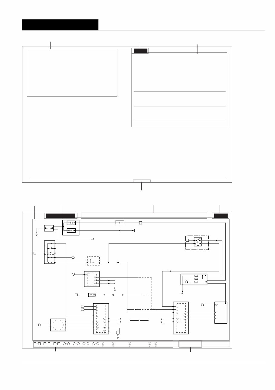
Battery; Starter; Generator: V6
Battery; Starter; Generator: V6
VARIANT: V6 Vehicles
VIN RANGE: All
DATE OF ISSUE: February 2004
f02_1_200045
Y
FPDB MEGAFUSE
STARTER MEGAFUSE
MEGAFUSE ASSEMBLY
BATTERY
FAULT;
CHARGE WARNING
B
JB1
CA288
CA280 CA304
450A
250A
CA302
CA135
R
R
R
R
01.1
REAR POWER DISTRIBUTION
FUSE BOX
WU
KEY-IN
0
FC18-5
I
II
III
FC18-7
FC18-4
NR
7
IGNITION SWITCH
FC18-1
WG
WB
01.5
IGNITION SWITCHED
CIRCUITS (II)
NG 56
S FC52-1
PASSIVE ANTI-THEFT SYSTEM TRANSCEIVER
FC52-3
FC52-4
FC52-2
WR
YR
BG
WU
FC37-3 FH53-3 FHS63 PI41-34 F1 5A
Y Y Y
PRIMARY JUNCTION FUSE BOX
GB2-9
GB2-10
GB1-10
GB1-9
GB2-13
GB2-16
GO
GR
B B
B B
B
B
+
O
P
P, N
P
18
II
PIS30
PI40AL TRANSMISSION CONTROL MODULE
92
NR GR GR GR GR
CA286-1 CA286-2 FH3-10 PI42-8 GB1-13
CLUTCH PEDAL SAFETY SWITCH
85
NG
WG 35
II FC8-14
FC8-15
FC9-31
FC9-16
FC9-32
FC8-5
PASSIVE
ANTI-THEFT
SYSTEM
LOGIC B
+
B
+
C
C D
I
D
P
P
INSTRUMENT CLUSTER
Y
FC9-28
G
FC9-29
B
FC8-32
B
FC8-2
FC38
20.1
20.1
O.K .TO START
Y Y
PIS27
GB1-14
(MAN / ROW)
(MAN / NAS)
(AUTO)
JUNCTION BLOCK
ST11 ST12 R
3
FRONT BULKHEAD
FH83 CA177
FH67
2
STARTER RELAY
NW GW
GO
65
ST4-1
R20
FRONT POWER DISTRIBUTION FUSE BOX
PI41-40
STARTER MOTOR
R
B
R
GW
ST5
ST6
ST3
ST2
GB1-6
PI1-41
PI1-31
PI1-6
PI1-124
PI1-123
GO
GR
Y
GENERATOR WARNING;
CLUTCH DISENGAGED
Y
G
20.1
20.1
P, N
START
ENGINE
CRANK
ENGINE
REQUEST
O
I
I I
I
O
C
C
ENGINE CONTROL MODULE
PI1-65
PI1-53
PI1-79
PI47-3
PI47-2
PI47-1
PI47-4
WG
YR
WR
GO 20
II
B
+
ST7
FIELD
CONTROL
GENERATOR
1 3 4 1 14 46 80 76 77 92 l l
15 45
ll ll S S
81 118
E E
Fig. 01.1 Fig. 01.2 Fig. 01.3 Fig. 01.4 Fig. 01.5 Fig. 01.6 Fig. 01.7
Input
Output
I
O
B
P
+ Battery Voltage
Power Ground
Sensor/Signal Supply V
Sensor/Signal Ground Serial and Encoded Data
CAN +
SCP
C
S D
D
–
D2B Network 2
Fig. 02.1
Fig. 02.1
NOTE: The values listed are approximately those that can be expected at the control module connector pins with all ciruit connections made and all
components connected and fitted.
The following abbreviations are used to represent values for Control Module Pin-Out data
I Input
O Output
B+ Battery Voltage
PG Power Ground
SS Sensor / Signal Supply V
SG Sensor / Signal Ground
C CAN Network
S SCP Network
D2 D2B Network
D Serial and Encoded Data
V Voltage (DC)
PWM Pulse Width Modulated
CAUTION: The information on this data page is furhished to aid the user in understanding circuit operation. THIS INFORMATION SHOULD BE USED FOR
REFERENCE ONLY.
Refer to the front of this book for detailed information and illustrations regarding the location and identification of harnesses, relays, fuses, grounds,
control modules and control module pins.
DATE OF ISSUE: February 2004
FOR CONTROL MODULE PIN-OUT INFORMATION, UNFOLD PAGE TO LEFT.
COMPONENTS
Component Connector(s) Connector Description Location
BATTERY — — LUGGAGE COMPARTMENT
CLUTCH PEDAL SAFETY SWITCH CA286 2-WAY / BLACK TOP OF CLUTCH PEDAL (BOTTOM SWITCH)
ENGINE CONTROL MODULE PI1 134-WAY / BLACK FRONT BULKHEAD, PASSENGER SIDE
FRONT POWER DISTRIBUTION FUSE BOX — — ENGINE COMPARTMENT, RH SIDE
GENERATOR (V6) PI47 4-WAY / BLACK ENGINE, RH SIDE, FRONT
ST7 EYELET
IGNITION SWITCH FC18 7-WAY / BLACK STEERING COLUMN COWLING
INSTRUMENT CLUSTER FC14 22-WAY / GREY INSTRUMENT PANEL
FC15 20-WAY / BLACK
FC63 22-WAY / BLACK
PASSIVE ANTI-THEFT SYSTEM TRANSCEIVER FC52 4-WAY / GREEN STEERING COLUMN, IGNITION SWITCH
PRIMARY JUNCTION FUSE BOX CA2 26-WAY / BLACK RH ‘A’ POST
CA56 8-WAY / BLACK
FC37 26-WAY / BLACK
FH7 6-WAY / BLACK
FH53 10-WAY / BLACK
STARTER MEGAFUSE — — LUGGAGE COMPARTMENT
STARTER MOTOR — — ENGINE BLOCK, RH SIDE
STARTER RELAY — — FRONT POWER DISTRIBUTION FUSE BOX – R20
TRANSMISSION CONTROL MODULE GB2 16-WAY / BLACK TRANSMISSION CONTROL VALVE ASSEMBLY
HARNESS IN-LINE CONNECTORS
Connector Connector Description / Location Location
FH3 16-WAY / BLUE / CABIN HARNESS TO FRONT HARNESS LH ‘A’ POST
GB1 16-WAY / GREY / ENGINE HARNESS TO TRANSMISSION HARNESS ADJACENT TO TRANSMISSION BELL HOUSING
PI41 42-WAY / BLACK / ENGINE HARNESS TO VEHICLE HARNESSES ENGINE COMPARTMENT, BULKHEAD, PASSENGER SIDE
PI42 8-WAY / BLACK / ENGINE HARNESS TO FRONT HARNESS ENGINE COMPARTMENT, BULKHEAD, PASSENGER SIDE
ST4 2-WAY / GREY / FRONT HARNESS TO STARTER LINK ENGINE COMPARTMENT, REARWARD OF RH WHEEL ARCH
GROUNDS
Ground Location
FC38 UNDER CENTER OF INSTRUMENT PANEL, ON TRANSMISSION TUNNEL
JB1 LUGGAGE COMPARTMENT, BATTERY GROUND
PI40 (LHD) ENGINE COMPARTMENT, BEHIND RH WHEEL ARCH LINER
PI40 (RHD) ENGINE COMPARTMENT, BEHIND LH WHEEL ARCH LINER
ST2 ENGINE COMPARTMENT, BEHIND LH WHEEL ARCH LINER
NOTE: Refer to the Appendix at the rear of this book for Network Messages.
Engine Control Module
Pin Description and Characteristic
I PI1–6 ENGINE CRANK: B+
I PI1–31 AUTOMATIC – PARK / NEUTRAL SIGNAL: B+ WHEN ACTIVATED
MANUAL, ROW – PARK / NEUTRAL SIGNAL: B+ WHEN IGNITION CRANK (III)
MANUAL, NAS – CLUTCH PEDAL SAFETY SWITCH (PARK / NEUTRAL SIGNAL): B+ WHEN ACTIVATED
O PI1–41 STARTER RELAY DRIVE: TO ACTIVATE, ECM SWITCHES CIRCUIT TO GROUND
O PI1–53 FUEL PUMP 2 DRIVE (TO FUEL PUMP 2 MODULE): PWM, 150 Hz, NORMAL POSITIVE DUTY CYCLE RANGE = 4% – 51%
I PI1–65 GENERATOR FIELD RETURN SIGNAL: VARIABLE VOLTAGE BY GENERATOR OPERATING CONDITION
I PI1–79 GENERATOR FAULT; CHARGE WARNING
C PI1–123 CAN –
C PI1–124 CAN +
Instrument Cluster
Pin Description and Characteristic
I FC14–2 KEY-IN AUDIBLE WARNING: B+ WHEN KEY IN
B+ FC14–3 IGNITION SWITCHED POWER SUPPLY (II): B+
SG FC14–14 SIGNAL GROUND: GROUND
PG FC15–2 POWER GROUND: GROUND
B+ FC15–3 BATTERY POWER SUPPLY (LOGIC): B+
I FC15–4 PATS GROUND: GROUND
D FC15–5 PATS TRANSCEIVER: ENCODED COMMUNICATION
D FC15–6 PATS TRANSCEIVER: ENCODED COMMUNICATION
C FC15–18 CAN +
C FC15–19 CAN –
Transmission Control Module
Pin Description and Characteristic
B+ GB2–9 IGNITION SWITCHED POWER SUPPLY: B+
O GB2–10 PARK / NEUTRAL SIGNAL: GROUND WHEN ACTIVATED
PG GB2–13 POWER GROUND: GROUND
PG GB2–16 POWER GROUND: GROUND
CONTROL MODULE PIN OUT INFORMATION FIGURE NUMBER COMPONENT, CONNECTOR AND GROUND
INFORMATION
DATE OF ISSUE
FIGURE MODEL RANGE AND YEAR TITLE FIGURE NUMBER
KEY TO REFERENCE SYMBOLS VARIANT, VIN RANGE AND DATE OF ISSUE
DATA PAGE
FIGURE PAGE
You're Reading a Preview
What's Included?
Fast Download Speeds
Offline Viewing
Access Contents & Bookmarks
Full Search Facility
Print one or all pages of your manual
$31.99
Viewed 39 Times Today


Secure transaction
What's Included?
Fast Download Speeds
Offline Viewing
Access Contents & Bookmarks
Full Search Facility
Print one or all pages of your manual
$31.99
The Jaguar XJ Service Manual covers the maintenance and repair procedures for the following models:
- 2003 Jaguar XJ
- 2004 Jaguar XJ
- 2005 Jaguar XJ
- 2006 Jaguar XJ
- 2007 Jaguar XJ
- 2008 Jaguar XJ
- 2009 Jaguar XJ
This comprehensive service manual is designed to assist Jaguar XJ owners in performing routine maintenance tasks and complete repairs with ease. Whether you need to perform a simple oil change or tackle a more complex engine repair, this manual provides detailed step-by-step instructions and illustrations to guide you through the process. Trust the Jaguar XJ Service Manual to help keep your vehicle running smoothly and efficiently.


